38 autoloc shaved door kit wiring diagram
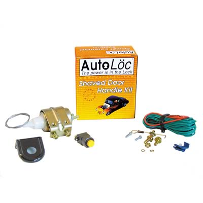
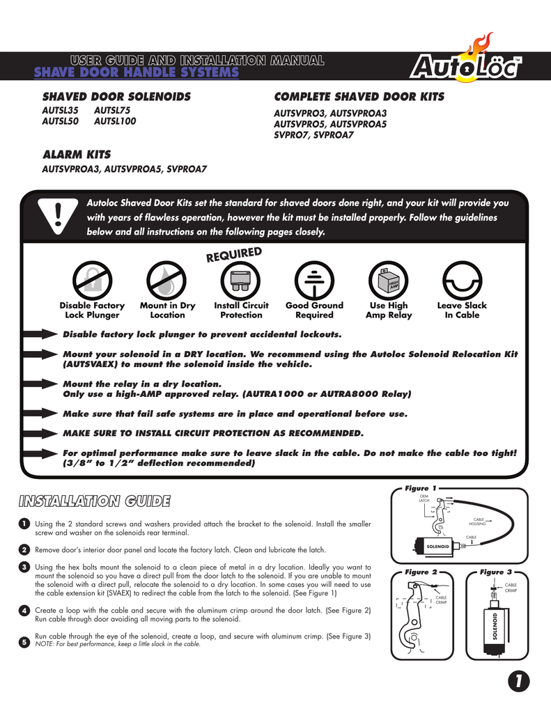
autoloc 140585 single shaved door handle latch popper kit, 29 door popper relay wiring diagram wiring database 2020, kmw performance air suspension bags cylinders struts, Click X to Close X digigov.eigenlytics.com Autoloc Shaved Door Kits set the standard for shaved doors done right, ... instructions on the following pages closely. ... receivers wiring diagram for.5 pages
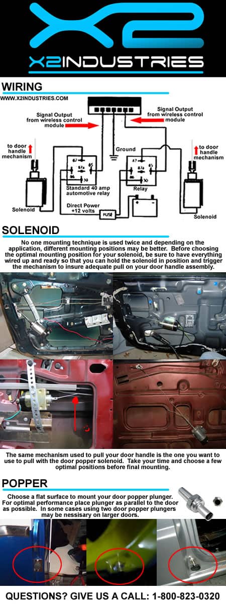
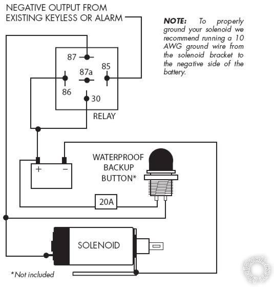
TECH SUPPORT: 503.693.1918 WWW.AUTOLOC.COM WIRING DIAGRAMS ALARM KITS SVPROA3, SVPROA5, SVPROA7 DOOR RELAY DOOR RELAY DRIVER + – PASSENGE R 87 87a 30 86 85 87 87a 30 86 85 FUSE 30A 2 Remote Receiver Connector Please reference the receivers wiring diagram for all other wire connections. IMPORTANT! BROWN/BLUE PURPLE GREEN/WHITE 1.

Autoloc shaved door kit wiring diagram
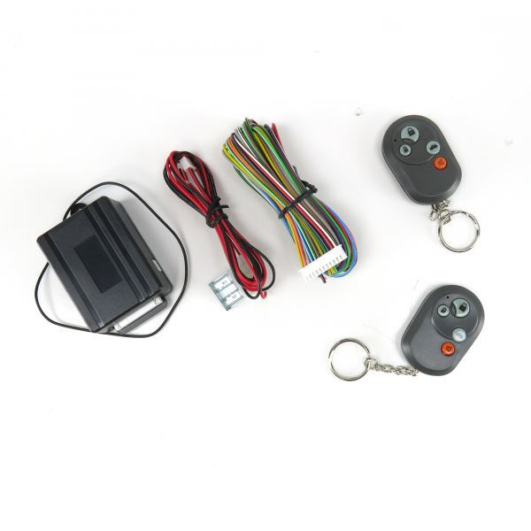
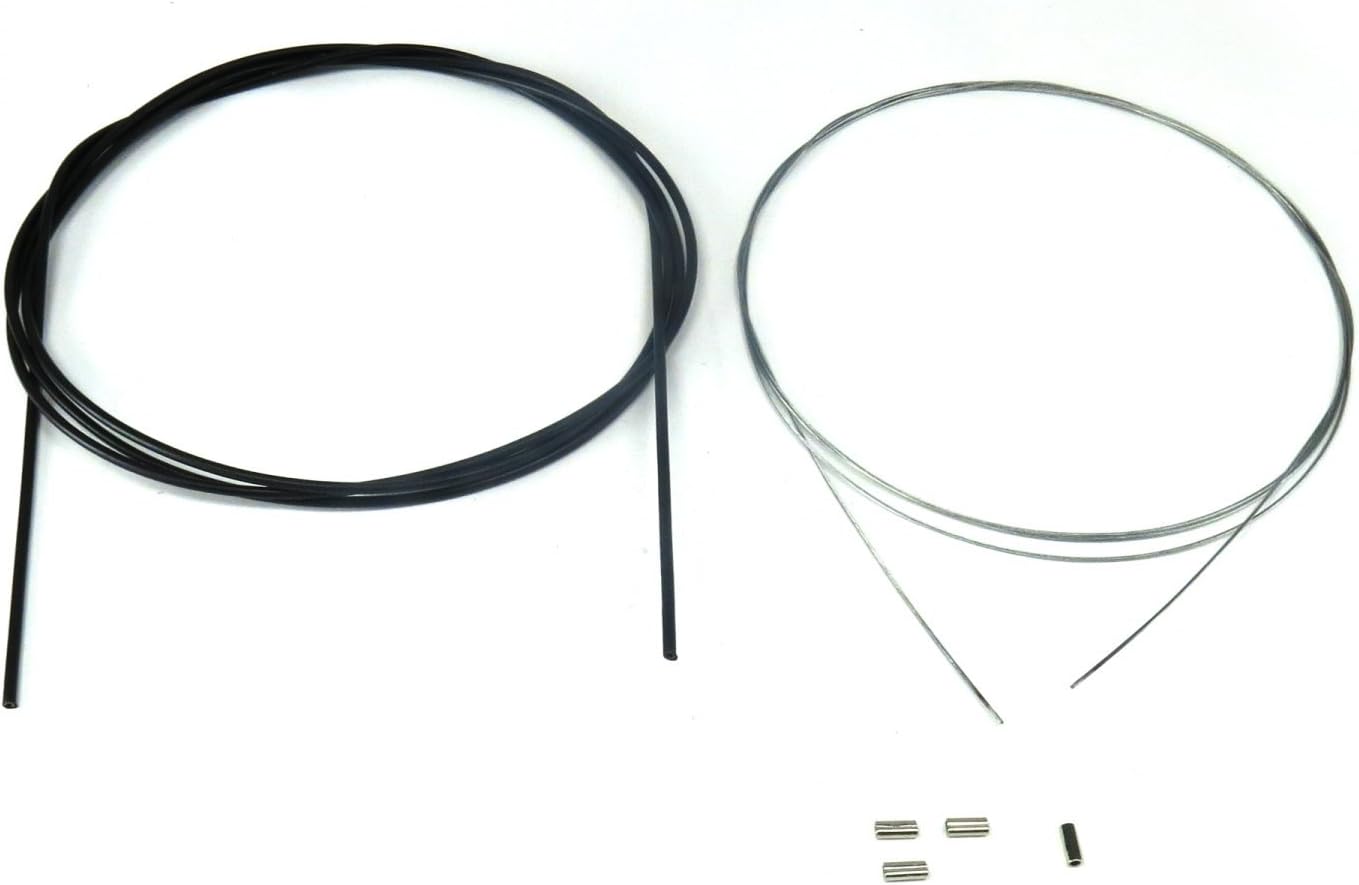
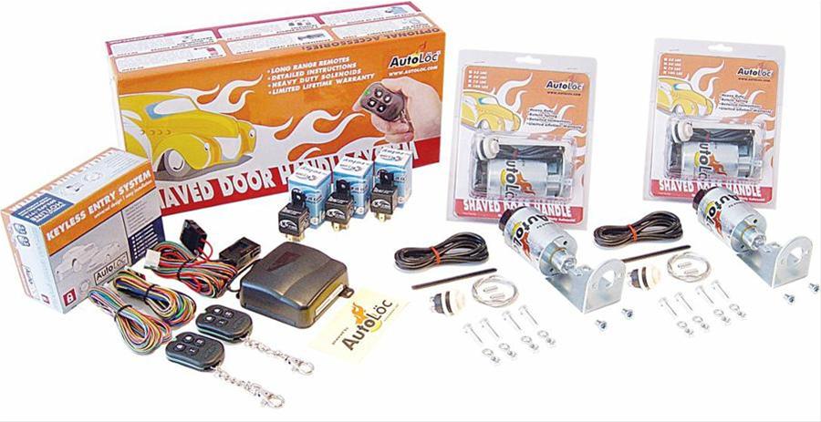
i just bought the autoloc shaved door kit from suicidedoors.com and i really want to install it but the wiring is pretty intimidating and the instructions... This shave door handle popper system includes detailed instructions, friendly tech. support, 1/16 stainless steel pre-stretched door popper cable, wiring, ... Autoloc Door Popper Wiring Diagram. AutoLoc's emergency door release system allows you to open your shaved door in the event of a dead 8 Function 50 Lbs Remote Shaved Door Popper Kit. Installation article on a Autoloc's remote entry system. entry kit, which included solenoids, remotes, door poppers, and bear-claw latches.
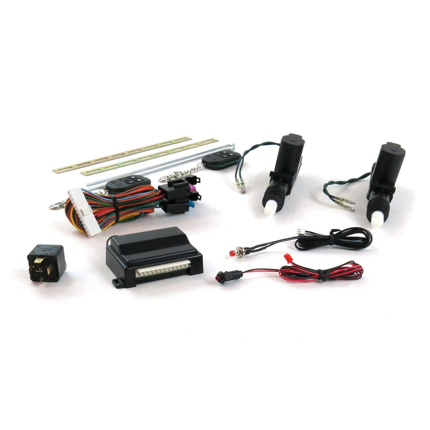
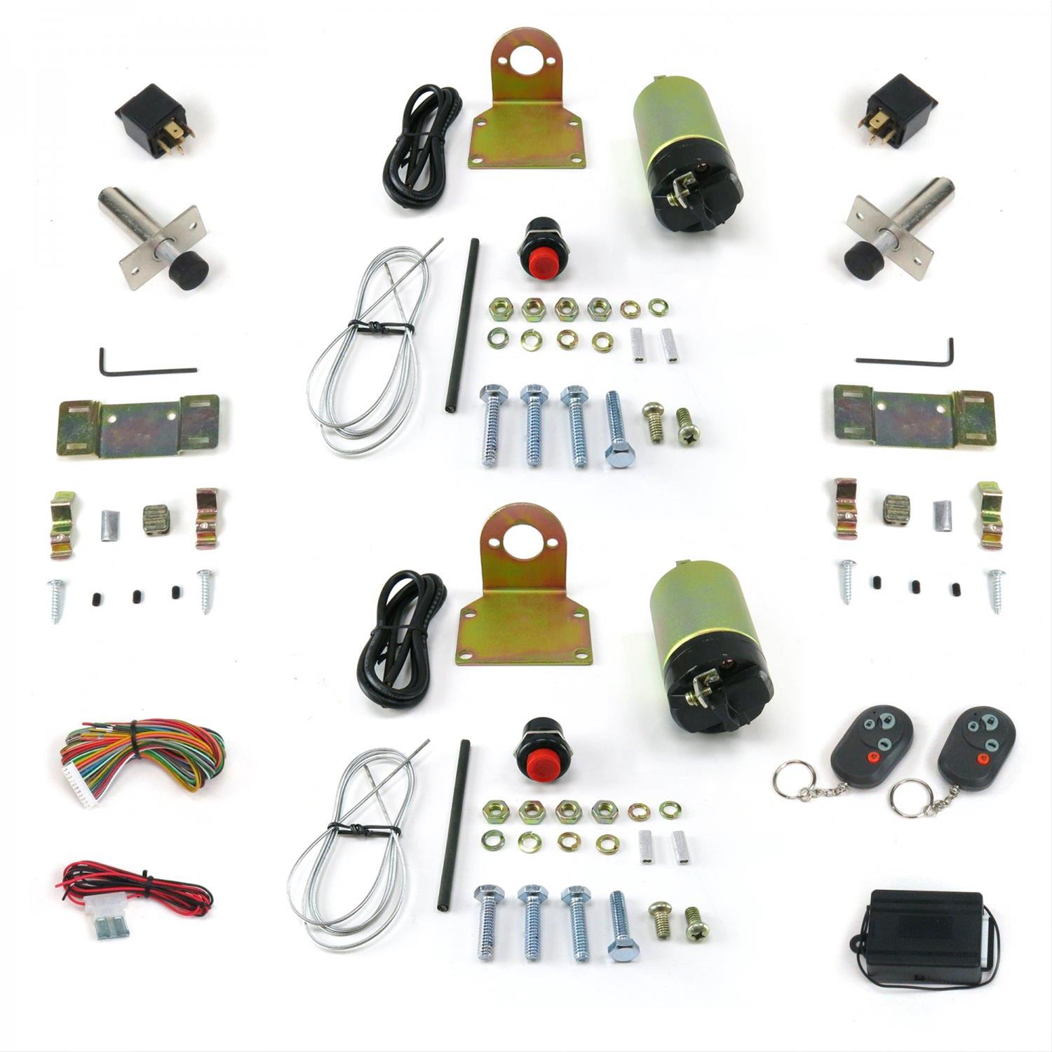
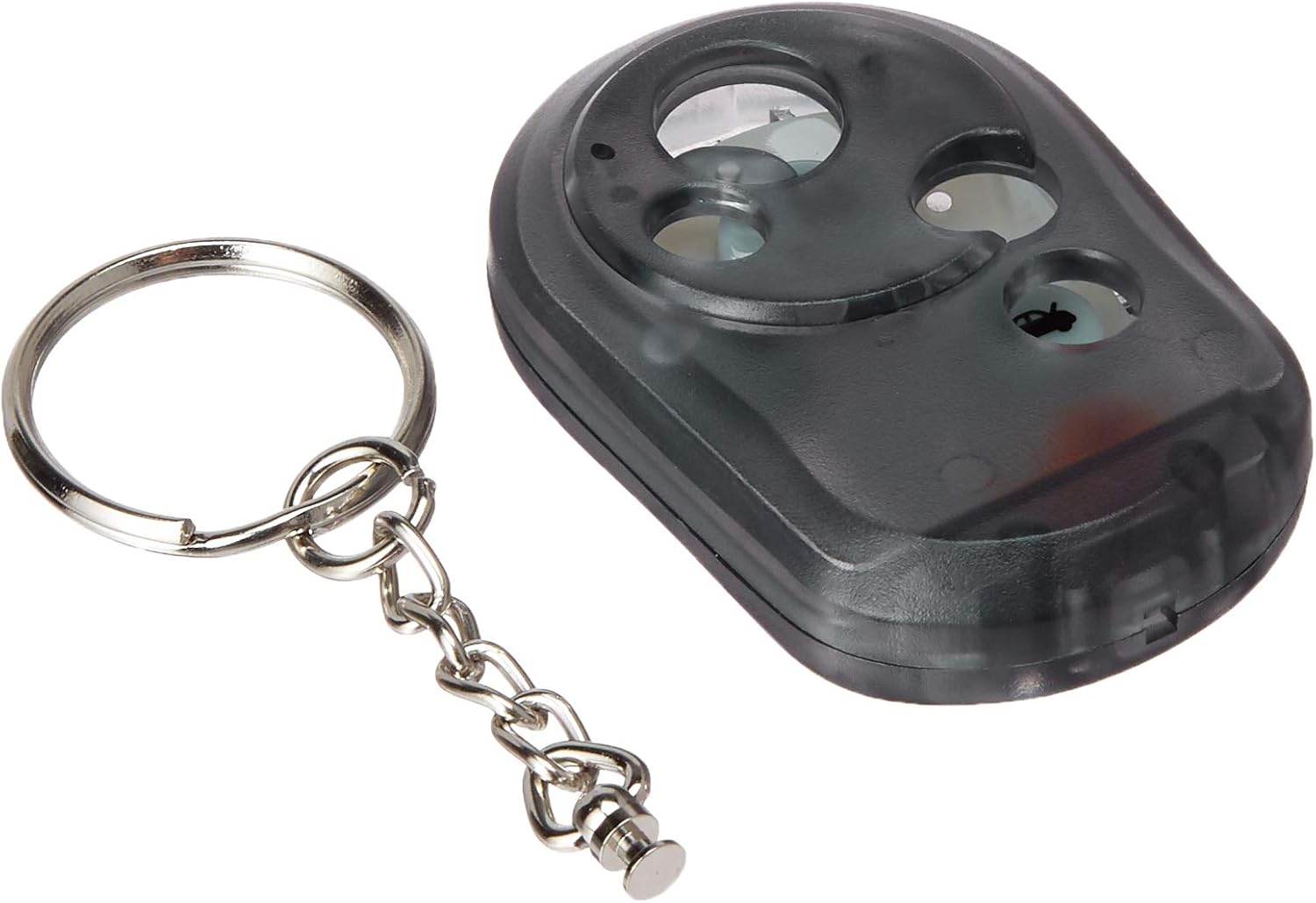
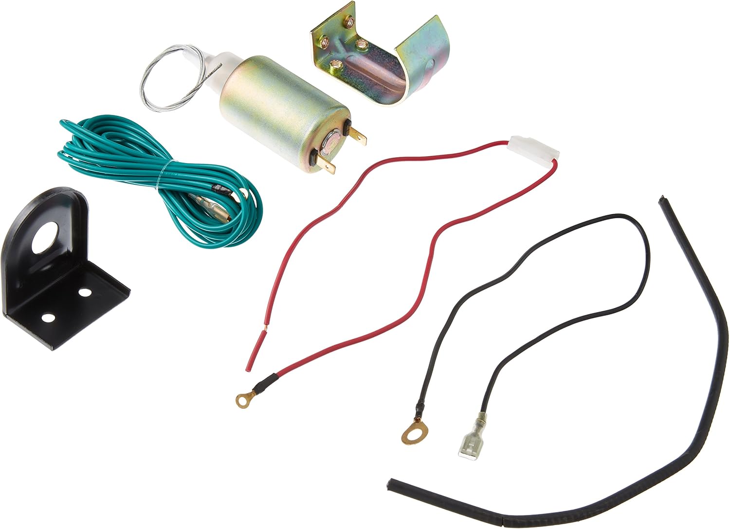
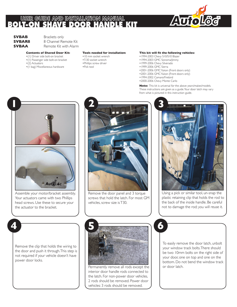
Autoloc shaved door kit wiring diagram. AUTOLOC.COM USER GUIDE AND INSTALLATION MANUAL WIRING DIAGRAMS SOLENOID INSTALLATION ALARM KITS SVPROA3, SVPROA5, SVPROA7 1. Using the 2 standard screws and ... AUTOLOC.COM. TECH SUPPORT: 503.693.1918. SHAVED DOOR HANDLE SYSTEMS. Button 1 ... Install the smaller screw and washer on the solenoids rear terminal.4 pages Contents of Shaved Door Kit: (1) Driver side bolt-on bracket (1) Passenger side bolt-on bracket (2) Actuators (1 bag) Miscellaneous hardware Assemble your motor/bracket assembly. Your actuators came with two Phillips head screws. Use these to secure your the actuator to the bracket. Remove the clip that holds the wiring to the door and push it ... Autoloc Shaved Door Kit Wiring Diagram from www.thirdgen.org To properly read a electrical wiring diagram, one provides to find out how the components inside the program operate. For instance , in case a module is usually powered up also it sends out a new signal of 50 percent the voltage plus the technician will not know this, he'd think he ...
Autoloc Shaved Door Kits set the standard for shaved doors done right, ... instructions on the following pages closely. ... receivers wiring diagram for. Autoloc Wiring Diagram. Shave door handle systems manualzz autoloc ca4000 install help keyless w alarm ih8mud forum kl400 user manual and installation pdf manualslib tech support 503 693 1918 www system wiring d 5 function entry with birt instructions open chit chat the classic zcar club catalogo 2010 by powertuning issuu how to an shaved kit 8 ... UNIVERSAL BOLT-ON SHAVED DOOR KIT USER GUIDE AND INSTALLATION MANUAL † Wiring Diagram 1 & 2 are for Bracket Only Version † Wiring Diagram 3 is for the Kit with Alarm System (SVBCA) † Wiring Diagram 4 is for the Kit with Remote (SVBCR8) USER GUIDE AND INSTALLATION MANUAL 1. Mount Actuators to the Bracket 2. Mount Actuators to the Vehicle 3. SPAL Shaved Door Handle Kit Shaved This kit is designed to Please refer to the diagrams on page 7 of this instruction manual for positive, negative, and.Contents of Shaved Door Kit: (1) Driver side bolt-on bracket (1) Passenger side bolt-on bracket the actuator to the bracket. Remove the clip that holds the wiring to the door and push it through.
TRUNK/SHAVED DOOR HANDLE TRIGGER CAR POSITIVE TRUNK RELEASE WIRE NEGATIVE FROM RECIEVER RELAY + – NOTE: If parking lights are negative trigger, then connect 30 to chassis ground. WIRING DIAGRAMS AUTOLOC DOORS CAR DOORS. Title: Autoloc Car Doors Installation Instructions Author: CARiD Subject: Autoloc Car Doors Installation Instructions Install the smaller screw and washer on the solenoids rear terminal. Remove door's interior door panel and locate the factory latch. Clean and lubricate the ... Autoloc Door Popper Wiring Diagram. AutoLoc's emergency door release system allows you to open your shaved door in the event of a dead 8 Function 50 Lbs Remote Shaved Door Popper Kit. Installation article on a Autoloc's remote entry system. entry kit, which included solenoids, remotes, door poppers, and bear-claw latches. This shave door handle popper system includes detailed instructions, friendly tech. support, 1/16 stainless steel pre-stretched door popper cable, wiring, ...
i just bought the autoloc shaved door kit from suicidedoors.com and i really want to install it but the wiring is pretty intimidating and the instructions...









0 Response to "38 autoloc shaved door kit wiring diagram"
Post a Comment