35 draw the shear diagram for the beam.
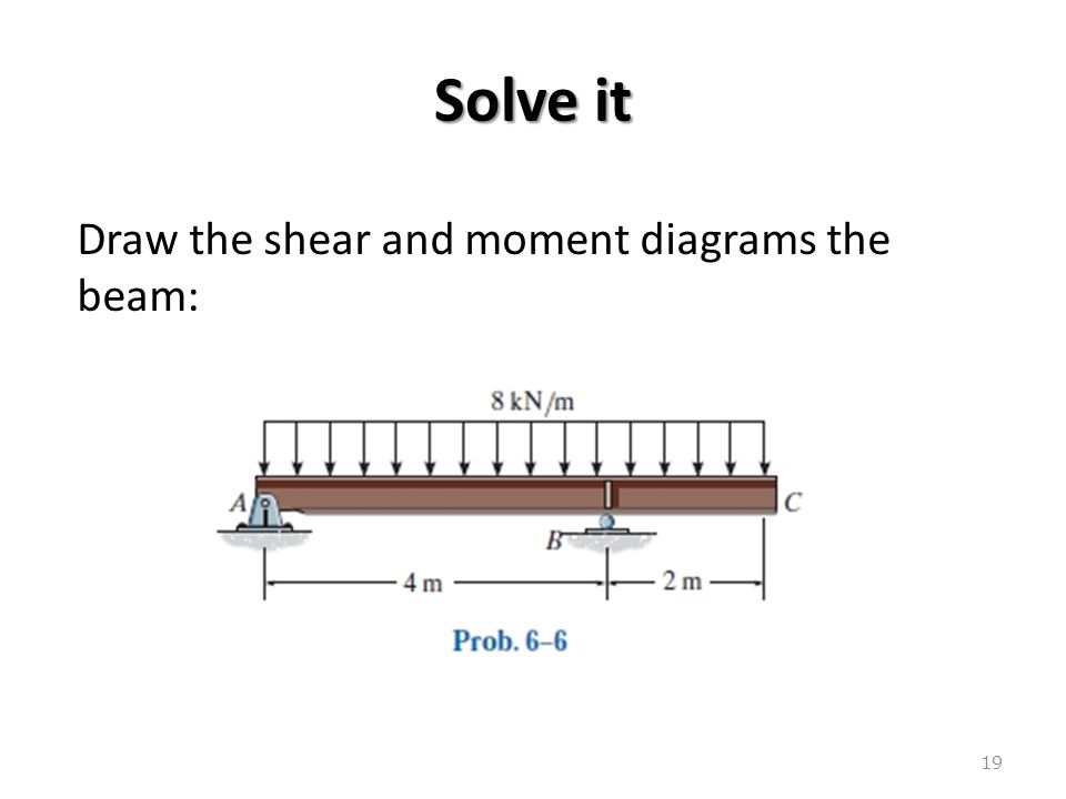
Nov 06, 2021 · • draw the sfd and bmd. The reactions shown on the Draw the shear and moment diagrams for the beam using the graphical method (i.e., using mathematical relations among load, shear and moment curves), and determine the shear and moment throughout the beam as functions of x (i.e., distance from a) for 0 < x < 4 m and 4 m < x < 6 m. Nov 04, 2021 · Draw the free body diagram of the . Method of are is one technique used to draw the shear and moment diagrams of a loaded beam. Draw the shear and moment diagrams of the beam. Draw the free body diagram for the beam. Source: www.steelconstruction.info. This is an example problem that will show you how to graphically draw a shear and moment ...
Shear Diagram. The shear of −2 kN at end A of the beam is plotted at x = 0, Fig. 6–16 c . The slopes are determined from the loading and from this the shear diagram is constructed, as indicated in the figure. In particular, notice the positive jump of 10 kN at x = 4 m due to the force B_y, as indicated in the figure. Moment Diagram.

Draw the shear diagram for the beam.
Draw the Shear and Moment diagrams for the beam. 1) Calculate the shear force and bending moment for the beam subjected to concentrated load as shown in the figure. Also, draw the shear force diagram (SFD) and the bending moment diagram (BMD). Fulcrumkild shear force bending moment diagram of cantilever beam exles ering intro cantilever beams moments and deflections a cantilever beam is subjected to various lo as shown in figure draw the shear force diagram and bending moment for ethiotutors shear force and bending moment diagram for cantilever beam civil snapshot. De 12 lesson 19 solved exles based on shear force and bending moment diagrams beam formulas with shear and mom solved 1 draw the shear and moment diagrams for simply chegg express the shear and moment functions in terms of x then draw diagram for simply supported beam study the w360 3 79 rolled steel beam ac shown below is.
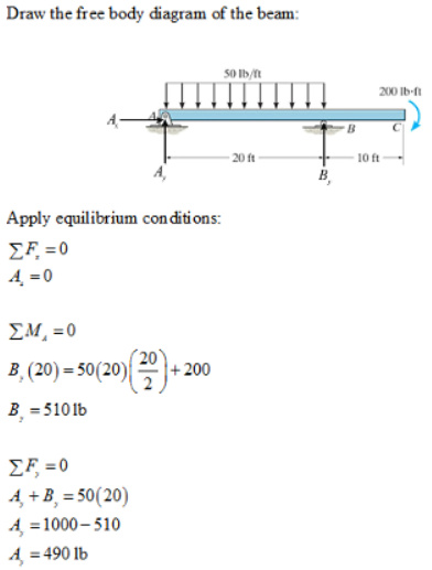
Draw the shear diagram for the beam.. PDF_C8_b (Shear Forces and Bending Moments in Beams) Q6: A simply supported beam with a triangularly distributed downward load is shown in Fig. Calculate reaction; draw shear force diagram; find location of V=0; calculate maximum moment, and draw the moment diagram. 6k/ft 9 ft RA = (27k)(9-6)/9= 9k A B F = (0.5x6x9) = 27k x = (2/3)(9) = 6 ft After completing this course… You will be fully competent in drawing shear force and bending moment diagrams for statically determinate beams and frames.; You will have a robust system of analysis that allows you to confidently tackle the analysis of any statically determinate structure.; You will understand the relationship between external loading and the shear forces and bending moments ... The reactions have been determined as shown on the beam’s free-body diagram, Fig. 6–6 b . Shear and Moment Functions. A free-body diagram of the left segment is shown in Fig. 6–6 c . As above, the trapezoidal loading is replaced by rectangular and triangular distributions. Note that the intensity of the triangular load at the section is ... Draw the shear diagram for the beam shown in the figure. Point Load. The load that has an influence only on a single point where it is acting on the beam is known as the point load, The magnitude ...
Shear and Moment Functions. Since there is a discontinuity of distributed load and also a concentrated load at the beam’s center, two regions of x must be considered in order to describe the shear and moment functions for the entire beam. M = ( − 2. 5 x 2 2 + 1 5. 7 5 x 2 + 9 2. 5) k N ⋅ m. Now, let's draw the shear and moment diagram (remember to draw the diagram on the compression side of the member). Shear Diagram 9.6 k 4.16 k 11.84 k 5.2 ft. Moment Diagram dV w dx Vx x( ) 4.16 0.8 Vx x( ) 4.16 0.8 0 4.16 5.2ft. 0.8 x 76.8 k ft. 76.8 k ft. 87.6 k ft. Shear and Moment Diagrams for Frames Example: Draw the shear and moment ... Draw a diagram of the shear force in the beam. The shear in the end of the beam starts out at 0 lbs. However, since there is a reaction of 22,500 lbs on the left side of the beam, it will create that much shear in that location. The line load will cause this shear to decrease along the length 4.3 Shear- Moment Equations and Shear-Moment Diagrams The determination of the internal force system acting at a given section of a beam : draw a free-body diagram that expose these forces and then compute the forces using equilibrium equations. The goal of the beam analysis -determine the shear force V and
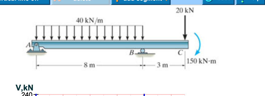
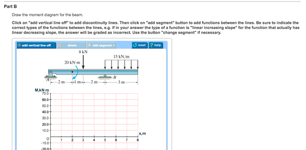
Section the beam at each distance x, and draw the free body diagram of one of the segments. Besure V (shear) and M (moments) are shown to be acting in their positive sense, in accordance with the sign convention that will be seen below. 3. The shear is obtained by summing forces perpendicular to the beams axis. 4. Part A Draw the shear diagram for the beam. Click on "add vertical line off" to add discontinuity lines. Then click on "add segment" button to add functions between the lines. Be sure to indicate the correct types of the functions between the lines, e.g. if in your answer the type of a function is "linear increasing slope" for the function that ... The shear diagram will plot out the internal shearing forces within a beam, or other body that is supporting multiple forces perpendicular to the length of the beam or body itself. The shear and moment diagrams are both used primarily in the analysis of horizontal beams in structures, such as floor joists, ceiling joists, and other horizontal ... First draw the free-body-diagram of the beam with sufficient room under it for the shear and moment diagrams (if needed, solve for support reactions first). 2. Draw the shear diagram under the free-body-diagram. The distributed load is the slope of the shear diagram and each point load represents a jump in the shear diagram. Label all the loads ...
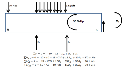
Consider the free body diagram of the beams ABE and CBD of the beam separately and apply the force equilibrium equations to calculate the unknown support reactions at A, B, C and D.Consider a section between each segment of the beam and apply the equilibrium equations to calculate the shear force and bending moment at each location of the beam.

Shear Force And Bending Moment Diagram For Cantilever Beam With Udl Mechanical Engineering Concepts And Principles
Draw shear force and bending moment diagrams [SFD and BMD] for beam. Also determine maximum hogging bending moment. 30N/m 4m [Ans: Max. Hogging bending moment = 735 kNm] Exercise Problems 4m3m VM-79 80. 5kN 8. A cantilever beam of span 6m is subjected to three point loads at 1/3rd points as shown in the Fig. given below. Draw SFD and BMD for ...
A Cantilever Beam Ab Supports Couple And Concentrated Load As Shown In The Figure Draw Shear Force Bending Moment Diagrams For This Bartleby. Draw The Shear Force And Bending Moment Diagrams For A Cantilever Beam Ab Carrying Uniform Load Of Intensity Q Over One Half Its Length See Figure Bartleby. Solved Express The Internal Shear And Moment In ...
Jan 28, · Step 2: Construct the shear force diagram for the beam with these reactions. Step 3: Using the shear force diagram, construct the bending moment diagram. You are trying to construct the moment diagram by jumping in the middle of the process without completing the basic steps (1 . It's because the shear diagram is triangular under a ...
Axial Force, Shear Force and Bending Moment Diagrams for Plane Frames Previous definitions developed for shear forces and bending moments are valid for both beam and frame structures. However, application of these definitions, developed for a horizontal beam, to a frame structure will require some adjustments.
Solved 1 Draw Shear Force And Bending Moment Diagrams For The Beams Subjected To The Loadings Shown Below 2 A Calculate The Shear Forces And Be Course Hero
Steps to draw Shear force and Bending moment diagrams. In SFD and BMD diagrams Shear force or Bending moment represents the ordinates, and the Length of the beam represents the abscissa. Consider the left or the right portion of the section. Add the forces (including reactions) normal to the beam on the one of the portion.
Transcribed image text: Part A Draw the shear diagram for the beam. Follow the sign convention Click on "add vertical line off" to add discontinuity lines. Then click on "add segment" button to add functions between the lines, Note 1 - Make sure you place only one vertical line at places that require a vertical line.
Nov 06, 2021 · Draw The Shear And Moment Diagrams For The Beam Loaded As Shown - B) if p = 20 kn and l = 6 m, draw the sfd and bmd for the beam. The support reactions a and c have been computed, and their values are shown in fig. Introduction notations relative to “shear and moment diagrams” e = modulus of elasticity, psi i = moment of inertia, in.4 l = span length of the bending member, ft. (a) is ...
Shear Diagram. The shear at end A is −2 kN. This value is plotted at x = 0, Fig. 6–15 c . Notice how the shear diagram is constructed by following the slopes defined by the loading w . The shear at x = 4 m is −5 kN, the reaction on the beam. This value can be verified by finding the area under the distributed loading,
- Draw the shear diagram for the beam. Follow the sign convention. - Draw the moment diagram for the beam. Follow the sign convention. Show transcribed image text Expert Answer. Who are the experts? Experts are tested by Chegg as specialists in their subject area. We review their content and use your feedback to keep the quality high.
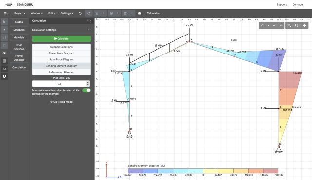
Beamguru Com Beam Calculator And Frame Truss Beam Calculator Online Draws Bending Moment Shear Force Axial Force
This problem has been solved! Draw the shear diagram for the beam. Draw the moment diagram for the beam. Determine the shear and moment throughout the beam as functions of x for 0 ≤ x ≤ 6ft (Please answer in terms of x) Determine the shear and moment throughout the beam as functions of x for 6ft ≤ x ≤ 9ft.
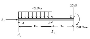
Draw The Shear Diagram For The Beam Draw The Moment Diagram For The Beam Home Work Help Learn Cbse Forum
Shear diagrams always begin and end at zero, with all of the forces on the member shown in between.Starting from the left, the first force you come across is the 10 lb downward force at the left end. This is the first point of data, draw a line from zero to negative 10.. Continuing on the next force is 21.67 lb upward at the A support.
Now, flip the beam horizontally 180º (or change the observation point, looking at the beam from the opposite side) and draw the diagrams, starting from the same point A. The diagrams will appear as follows: Note that, while the shear force diagrams appeared to be mirrored images (flipped horizontally), the bending moment diagram is not affected.
drawing the S/B diagrams. [1,2]The method of sections can be used to determine fully the shear force and bending moment at any cross-section of beams and to draw the S/B diagrams. When there are several external forces on a beam, the beam must be divided into several segments. The method of sections will be used repeatedly in each segment.
Part A Draw the shear diagram for the beam. Follow the sign convention. (Figure 1) Click on "add vertical line off to add discontinulty lines. Then click on "add segment" button to add functions between the lines. Note 1 - You should not draw an "extra" discontinuity line at the point where the curve passes the x- axis.
Solved Draw The Shear Force Bending Moment Diagrams Of The Beam Shown In The Figure Below Taking Into Account The Given Loading Make Detailed Cal Course Hero
Write shear and moment equations for the beams in the following problems. In each problem, let x be the distance measured from left end of the beam. Also, draw shear and moment diagrams, specifying values at all change of loading positions and at points of zero shear. Neglect the mass of the beam in each problem.
De 12 lesson 19 solved exles based on shear force and bending moment diagrams beam formulas with shear and mom solved 1 draw the shear and moment diagrams for simply chegg express the shear and moment functions in terms of x then draw diagram for simply supported beam study the w360 3 79 rolled steel beam ac shown below is.
Fulcrumkild shear force bending moment diagram of cantilever beam exles ering intro cantilever beams moments and deflections a cantilever beam is subjected to various lo as shown in figure draw the shear force diagram and bending moment for ethiotutors shear force and bending moment diagram for cantilever beam civil snapshot.
Ultimate Guide To Shear Force And Bending Moment Diagrams Engineer4free The 1 Source For Free Engineering Tutorials
Draw the Shear and Moment diagrams for the beam. 1) Calculate the shear force and bending moment for the beam subjected to concentrated load as shown in the figure. Also, draw the shear force diagram (SFD) and the bending moment diagram (BMD).

For The Figure Below Draw A Draw The Shear Diagram For The Beam Follow The Sign Convention B Draw The Moment Diagram For The Beam Follow The Sign Convention Study Com

A Beam Is Shown In The Figure Below Part A Draw A Shear Diagram For The Beam Part B Draw The Moment Diagram For Th Homeworklib


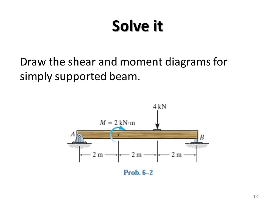

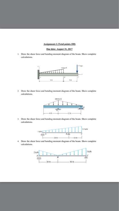




0 Response to "35 draw the shear diagram for the beam."
Post a Comment