36 iron carbon equilibrium diagram
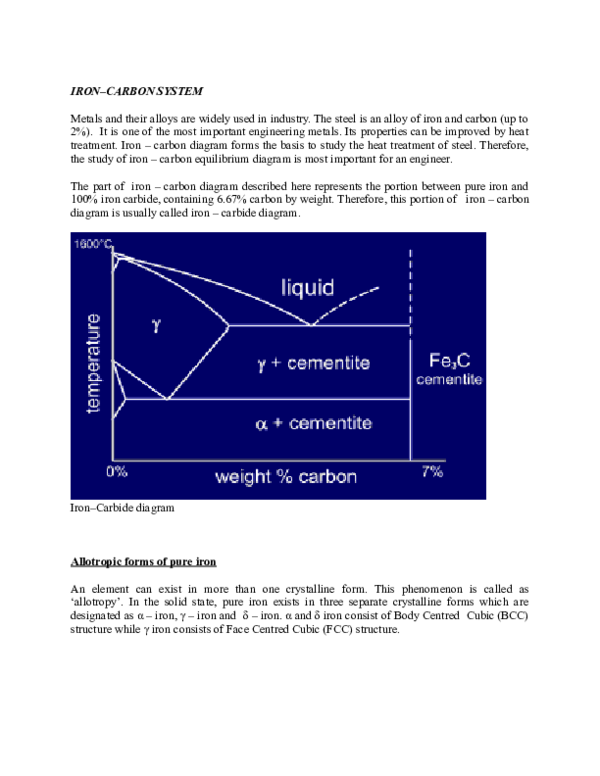
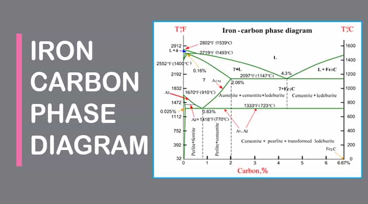
› academic-files › ArabicIRON CARBON PHASE DIAGRAM Cementite or iron carbide, is very hard, brittle intermetallic compound of iron & carbon, as Fe 3 C, contains 6.67 % C. It is the hardest structure that appears on the diagram, exact melting point unknown. Its crystal structure is orthorhombic. It is has low tensile strength (approx. 5,000 psi), but high compressive strength. › metallurgy › ironIron-Carbon Equilibrium Diagram | Metallurgy Iron-Cementite diagram is not a true equilibrium diagram, since equilibrium means no change of phase with time, however long it may be. Graphite is more stable form of carbon. Cementite is a metastable phase, which decomposes to graphite if given long periods of time. Graphitisation, however, rarely occurs in steels and may take years to form.
(PDF) iron-carbon thermal equilibrium diagram - ResearchGate Part of the iron-carbon thermal equilibrium diagram A diagram showing the relationship between carbon content, microstructure and Mechanical properties of plain carbon steels in the normalized ...

Iron carbon equilibrium diagram
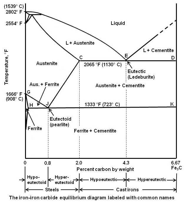
Sketch and explain the iron carbon equilibrium diagram ... The part of iron-carbon alloy system diagram between pure iron and an interstitial compound, iron carbide (Fe 3 C), containing 6.67 percent carbon by weight is called iron-iron carbide equilibrium diagram. IRON-CARBON EQUILIBRIUM DIAGRAM - Engineers Gallery IRON-CARBON EQUILIBRIUM DIAGRAM Fig. shows, the Fe-C equilibrium diagram in which various structure (obtained during heating and cooling), phases and microscopic constituents of various kinds of steel and cast iron are depicted. The main structures, significance of various lines and critical points are discussed as under. 1. Iron Carbon Equilibrium Diagram, Ttt Diagram and Heat ... DIFFERENCE BETWEEN IRON-CARBON & TTT • Study of Fe-C diagram shows study of cooled steels under non- equilibrium conditions. • Doesn't involve reaction condition during heat treatment of steel. • It only shows phases & resulting microstructure corresponding to equilibrium conditions.
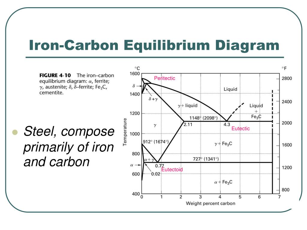
Iron carbon equilibrium diagram. Iron Carbon Equilibrium Diagram with Explanation [Phase ... The Iron carbon equilibrium diagram (also called the iron carbon phase diagram) is a graphic representation of the respective microstructure states of the alloy iron - carbon (Fe-C) depending on temperature and carbon content. The iron carbon phase diagram is commonly used to fully understand the various phases of steel and cast iron. Iron-Carbon Diagram and Its Reactions | Metallurgy In Fe-Fe 3 C diagram, three important invariant (at a constant temperature) reactions take place as described below: . 1. Peritectic Reaction: A peritectic reaction, in general, can be represented by an equation: where, L represents a liquid of fixed composition, S 1 and S 2 are two different solids of fixed composition each. Fig. 1.23 illustrates the peritectic region of Fe-Fe 3 C diagram. What is the Iron-Carbon Phase Diagram? - Engineering Choice What is the iron carbon diagram? The Fe - C diagram (also called the iron-carbon phase or equilibrium diagram) is a graphic representation of the respective microstructure states of the alloy iron-carbon (Fe-C) depending on temperature and carbon content. To explain this diagram, an introduction about metal structures and pure iron must be done. Crystal Structures, Equilibrium Phases and the Iron-Carbon ... Crystal Structures, Equilibrium Phases and the Iron-Carbon Phase Diagram The material properties of Irons and Steels are highly dependent on their Carbon content. This is because Carbon content changes both the crystal structures of an iron-carbon alloy and the resulting microstructures that form.
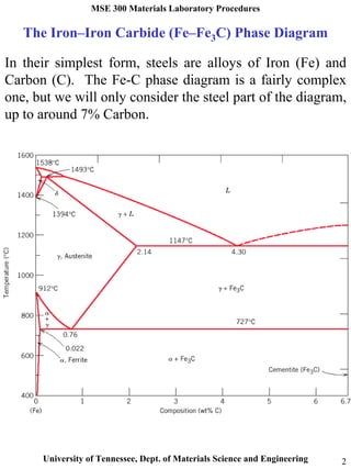
The Iron-Carbon Phase Diagram - IspatGuru The iron -carbon phase diagram in Fig 2 actually shows two diagrams namely (i) the stable iron-graphite diagram (red lines), (ii) and the metastable Fe-Fe3C diagram. Cementite is metastable, and the true equilibrium is to be between iron and graphite (C). The Iron-Iron Carbide Equilibrium Diagram The Iron-Iron Carbide Diagram The part of iron-carbon alloy system diagram between pure iron and an interstitial compound, iron carbide (Fe 3 C), containing 6.67 percent carbon by weight is called iron-iron carbide equilibrium diagram. What is the iron carbon equilibrium diagram ... The part of iron-carbon alloy system diagram between pure iron and an interstitial compound, iron carbide (Fe3C), containing 6.67 percent carbon by weight is called iron-iron carbide equilibrium diagram. The diagram shows three horizontal lines which indicate isothermal reactions. PDF Material Science and Metallurgy Topic:~Iron Iron-Carbide ... The Iron-Iron Carbide Diagram • A map of the temperature at which different phase changes occur on very slow heating and cooling in relation to Carbon, is called Iron- Carbon Diagram. • Iron- Carbon diagram shows - The type of alloys formed under very slow cooling, - Proper heat-treatment temperature and
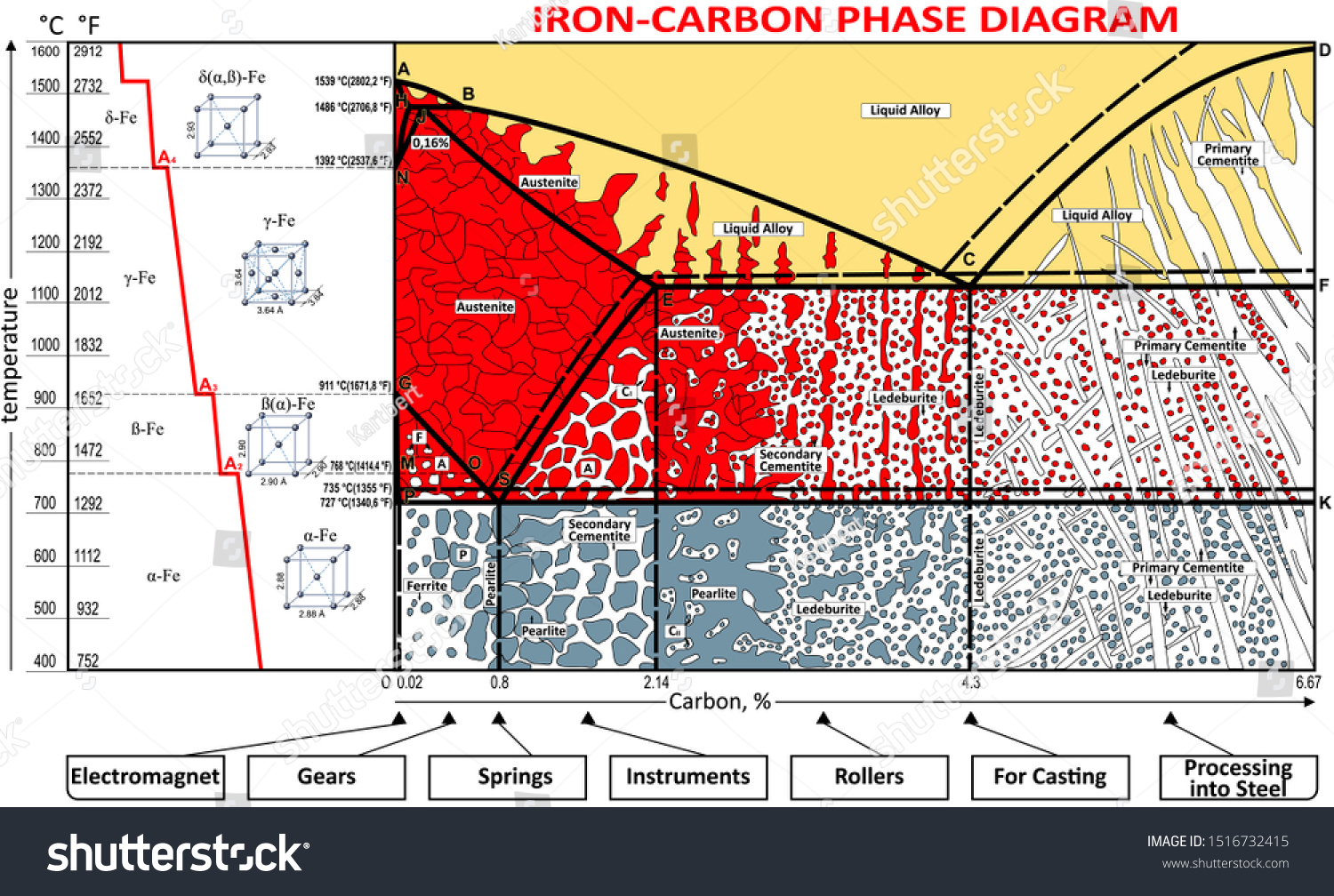
Iron carbon diagram presentation - SlideShare the iron-iron carbide diagram a map of the temperature at which different phase changes occur on very slow heating and cooling in relation to carbon, is called iron- carbon diagram. iron- carbon diagram shows the type of alloys formed under very slow cooling, proper heat-treatment temperature and how the properties of steels and … IRON CARBIDE EQUILIBRIUM DIAGRAM - Marine Inbox IRON CARBIDE EQUILIBRIUM DIAGRAM. The part of iron and carbon alloy system line diagram representation of unalloyed iron and an interstitial compound, iron carbide (Fe3C), containing 6.67 percent carbon by weight is called iron-iron carbide equilibrium diagram. It should be noted that though it is called as equilibrium diagram, it is not a true ... en.wikipedia.org › wiki › Phase_(matter)Phase (matter) - Wikipedia Iron-carbon phase diagram, showing the conditions necessary to form different phases Distinct phases may be described as different states of matter such as gas , liquid , solid , plasma or Bose–Einstein condensate . Iron-Carbon Diagram Explanation [PDF] - Mechanical E-Notes Iron-Carbon Phase Diagram with Detailed Explanation: If the percentage of the carbon is in the range of 0 to 2.11 % then it is called Steel and if the percentage of carbon is in the range of 2.11 to 6.67% then it is called Cast iron. As the carbon content increases, it produces more Iron-Carbide volume and that phase will exhibit high hardness.
The Effects of Alloying Elements on Iron-Carbon Alloys ...
What is Iron carbon diagram in hindi || Iron carbon ... Click here to download our apphttps://edumartin.page.link/jLFrTry this free mock testhttps://tinyurl.com/yjmfa72v Iron carbon diagram part 1 videohttps://www...
![Iron-Carbon Phase Diagram Explained [with Graphs]](https://fractory.com/wp-content/uploads/2020/03/Iron-carbon-phase-diagram-explained.jpg)
Iron-Carbon Phase Diagram Explained [with Graphs]
Ch. 5: Equilibrium Phase Diagrams and the Iron-Carbon ... Ch. 5: Equilibrium Phase Diagrams and the Iron-Carbon System. Composition is fixed. Not much usage to materials area. Shows the phase change occurring within a material of particular composition, as the material is cooled. This is where the Equilibrium Phase Diagrams are derived.
Phase Diagrams:
PDF The C-Fe (Carbon-Iron) System - gotrawama.eu phase diagram has not been well established---in the temperature, composition, and pressure ranges not related directly to iron and steel making. In the present evaluation, the assessed stable Fe-C (graphite) and metastable Fe-Fe3C (cementite) equilibrium phase diagrams for 0 to 25 at.%

How to Remember Iron Carbon Phase Diagram
Introduction to Iron-Carbon Equilibrium Diagram ... Cast iron having 6.67% carbon is possessing complete structure of cementite. Free cementite is found in all steel containing more than 0.83% carbon. It increases with increase in carbon % as reflected in Fe-C Equilibrium diagram. It is extremely hard. The hardness and brittleness of cast iron is believed to be due to the presence of the cementite.
iron carbon phase diagram — Steemit
en.wikipedia.org › wiki › Ellingham_diagramEllingham diagram - Wikipedia The Ellingham diagram indicates that in this range carbon monoxide acts as a stronger reducing agent than carbon since the process 2 CO + O 2 → 2 CO 2. has a more-negative free energy change than the process: 2 C + O 2 → 2 CO.

Can Someone Explain Me About This Iron - Carbon Phase Diagram ...
Iron-Carbon Phase Diagram Explained [with Graphs] Iron-Carbon Phase Diagram The iron-carbon phase diagram is widely used to understand the different phases of steel and cast iron. Both steel and cast iron are a mix of iron and carbon. Also, both alloys contain a small amount of trace elements.
![Iron-Carbon Phase Diagram Explained [with Graphs]](https://fractory.com/wp-content/uploads/2020/03/Phase-diagram-of-steel-and-cast-iron.jpg)
Iron-Carbon Phase Diagram Explained [with Graphs]
Iron Carbon equilibrium diagram | Tamil | Polytechnic TRB ... This video will clear all your questions regarding Iron Carbon equilibrium diagram. Explained in tamil.This will give you clear idea about the phase changes ...

iron carbon phase diagram - Google Search | Carbon ...
The Iron-Carbon Equilibrium Diagram :: Total Materia Article The iron-carbon diagram provides a valuable foundation on which to build knowledge of both plain carbon and alloy steels in their immense variety. Fig. 1. The iron-carbon diagram. It should first be pointed out that the normal equilibrium diagram really represents the metastable equilibrium between iron and iron carbide (cementite).
Iron Carbon Alloys - Metallurgy - Engineering Reference with ...
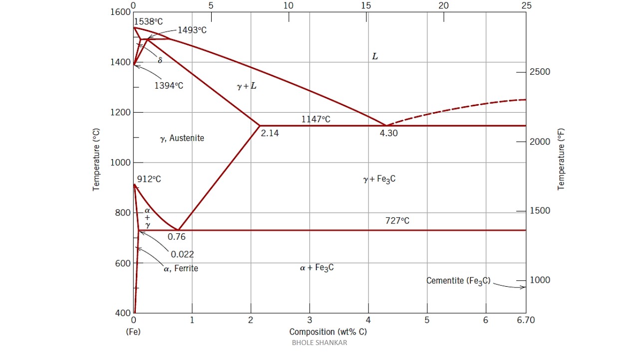
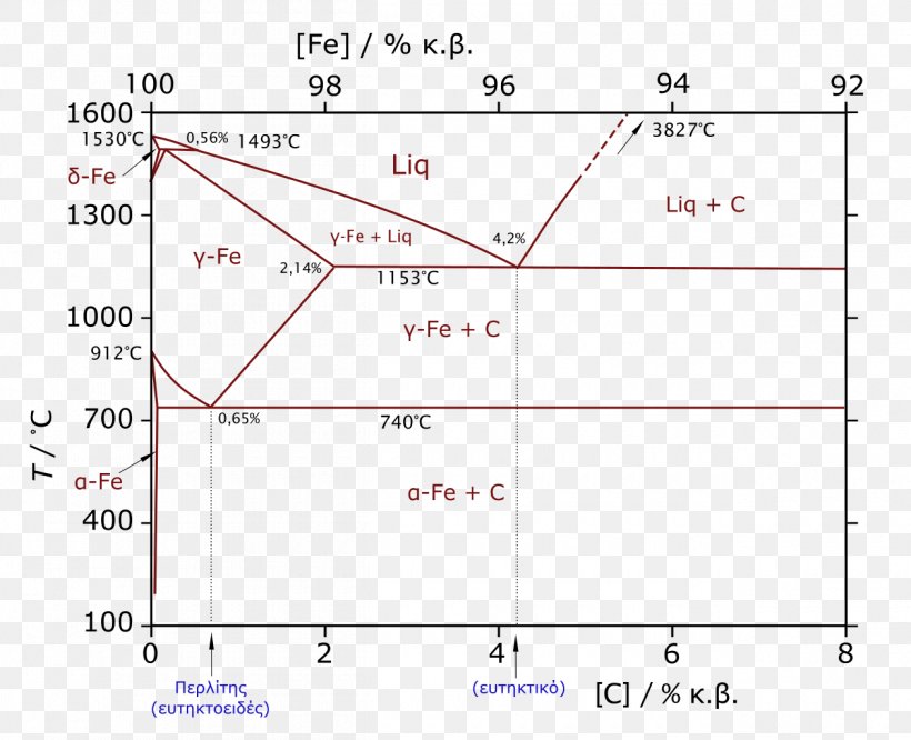
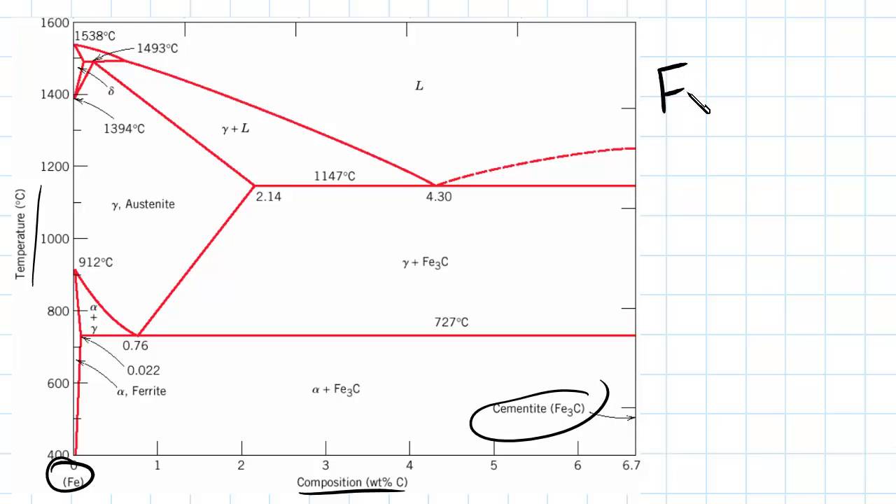
Iron Carbon Diagram MCQ [Free PDF] - Objective Question ... Three important transformations of the iron-carbon equilibrium diagram Eutectoid Reaction At temperature 727° C and carbon composition 0.8% Austenite (γ) (S) ⇄ Ferrite (α-iron) (S) + Carbide (Fe3C) (S) One solid converted into two solids. Eutectic reaction At temperature 1147° C and carbon composition 4.3%.
IRON –CARBON PHASE DIAGRAM
Iron Carbon Phase or Equilibrium Diagram or Iron Carbide ... Iron carbide equilibrium diagram shows us metastable conditions, one can achieve equilibrium changes under slow heating and cooling. Importance of Iron Carbon Equilibrium Diagram According to the requirements of different applications, we can develop new alloys by handing them at different temperatures and changing the compositions of carbon in it.
Iron Phase Diagram - Roy Mech
250+ TOP MCQs on Iron Carbon Phase Diagram and Answers 8. The percentage of carbon at peritectic point in Fe-C phase diagram is? a) 2.1 b) 4.3 c) 0.83 d) 0.18. Answer: d Clarification: Percentage of carbon at peritectic point = 0.18%. Peritectic reaction in iron-carbon phase diagram takes place at constant temperature of 1493 o C. 9. Which of the following reaction does not exhibit mushy zone in Fe ...

Heat Treater's Color Poster - ASM International
PDF Iron-Iron carbide (Fe-Fe C) Phase Equilibrium Diagram Iron-Iron carbide (Fe-Fe 3 C) Phase Equilibrium Diagram In this diagram weight % C is plotted along horizontal axis and temperature along vertical axis. The diagram shows the phases present at various temperatures for very slowly cooled Fe-C alloys with carbon content up to 6.67%. Information given by the diagram: 1. Solid phases in the phase ...
DOC) IRON CARBON SYSTEM | dhanushka priyankara - Academia.edu
Iron Carbon Equilibrium Diagram, Ttt Diagram and Heat ... DIFFERENCE BETWEEN IRON-CARBON & TTT • Study of Fe-C diagram shows study of cooled steels under non- equilibrium conditions. • Doesn't involve reaction condition during heat treatment of steel. • It only shows phases & resulting microstructure corresponding to equilibrium conditions.

IRON-CARBON EQUILIBRIUM DIAGRAM: Austenite, Ferrite ...
IRON-CARBON EQUILIBRIUM DIAGRAM - Engineers Gallery IRON-CARBON EQUILIBRIUM DIAGRAM Fig. shows, the Fe-C equilibrium diagram in which various structure (obtained during heating and cooling), phases and microscopic constituents of various kinds of steel and cast iron are depicted. The main structures, significance of various lines and critical points are discussed as under. 1.
Iron-Carbon Phase Diagram
Sketch and explain the iron carbon equilibrium diagram ... The part of iron-carbon alloy system diagram between pure iron and an interstitial compound, iron carbide (Fe 3 C), containing 6.67 percent carbon by weight is called iron-iron carbide equilibrium diagram.
Practical Maintenance » Blog Archive » The Iron-Iron Carbide ...
Tikalon Blog by Dev Gualtieri

Iron-Carbide Phase Diagram - Points & Lines Diagram | Quizlet
3 The true equilibrium iron-carbon phase diagram with ...
![The iron-carbon phase diagram [46]. | Download Scientific Diagram](https://www.researchgate.net/profile/Muna-Abbass/publication/293333803/figure/fig2/AS:669013386469398@1536516629671/Figure-2-11-The-iron-carbon-phase-diagram-46.png)
The iron-carbon phase diagram [46]. | Download Scientific Diagram
PPT - Chapter 4 Equilibrium Phase Diagrams and The Iron ...

IRON CARBON EQUILLIBRIUM DIAGRAM WITH EXPLANATION
Iron Carbon Phase or Equilibrium Diagram or Iron Carbide ...
Iron-Carbon Phase Diagram Graphite, PNG, 1260x1024px, Phase ...

Iron-Carbon Equilibrium Phase Diagram ... | Diagram ...
Coloring Vector Ironcarbon Phase Diagram Stock Vector ...
What is the use of an iron carbide phase diagram? - Quora

15. From the iron-carbon phase diagram (see Figure below) a ...
![Iron-carbon phase diagram [SubsTech]](https://www.substech.com/dokuwiki/lib/exe/fetch.php?w=&h=&cache=cache&media=iron-carbon_diagram.png)
Iron-carbon phase diagram [SubsTech]
Iron-Carbon Phase

Please answer the following question regarding the iron-iron ...
Cast irons
Introduction to Iron Carbon Phase Diagram | Engineering Materials

Equilibrium microstructural transformations in steel – steel ...

Iron-Carbon Diagram, Transformation in steel, Transformation ...

The Iron-Iron Carbide Phase Diagram - ppt video online download
0 Response to "36 iron carbon equilibrium diagram"
Post a Comment