35 how to draw phasor diagram
Phasor diagrams We cannot provide a description for this page right now How to draw Phasor diagram for Electrical Circuits - Quora How do I draw any phasor diagram easily? The thumb rule that you should keep in mind while drawing the phasor diagram is: In a parallel circuit take source voltage as reference and in a series circuit take source current as reference.This is done to simplify the complexity of the network.
How to draw phasor diagrams? - Electronics Forums So I'm doing an assignment and it requires me to draw the phasor diagrams for the circuit below. I need to draw the phases for each of the components, with the voltage source being the reference phase. So I understand what phasor diagrams look like, but have no idea how to actually draw them.

How to draw phasor diagram
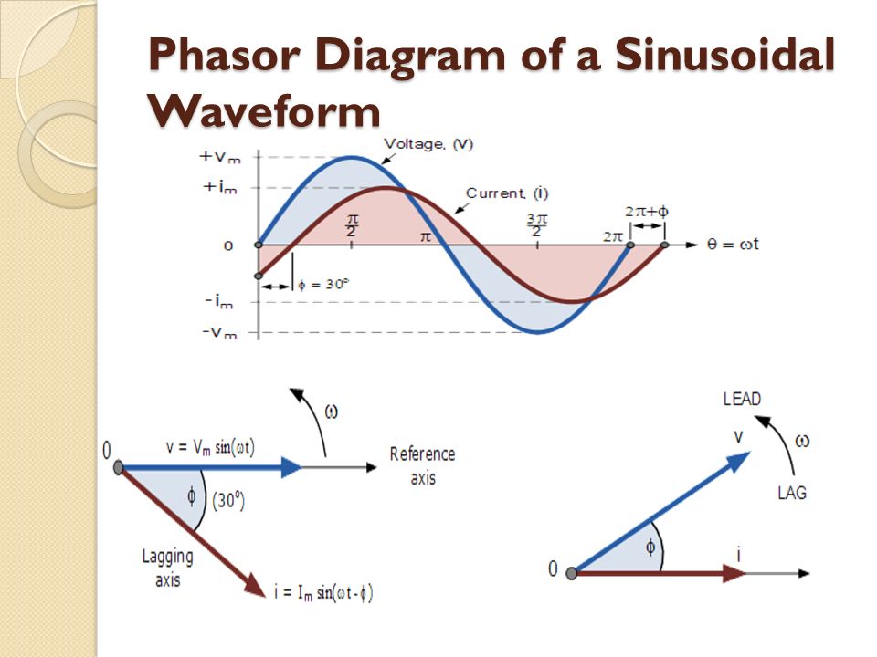
PDF Phasors Final 3 9 2012 Ron Alexander.ppt - Aventri convenience, on the diagrams the phasor is al ways shown "fixed" for the given condition. •Phasor diagrams require a circuit di agram. The phasor diagram… has a indeterminate or vague meaning unless it is accompanied by a circuit diagram. •The assumed directions and polarities are not critic al, as the phasor diagram will confirm if the Phasor Diagram and Phasor Addition - Electrically 4 U Choose a phasor as a reference and draw it along the X-axis. Now, draw the other phasors at that instant, one after another. To get the resultant phasor, join the origin of the first phasor and the endpoint of the final phasor. Now, the length of the phasor from origin to the last point represents the magnitude of the resultant phasor. Phasor Diagram and Phasor Algebra used in AC Circuits December 26, 2019 - The phasor diagram is drawn corresponding to time zero ( t = 0 ) on the horizontal axis. The lengths of the phasors are proportional to the values of the voltage, ( V ) and the current, ( I ) at the instant in time that the phasor diagram is drawn. The current phasor lags the voltage phasor ...
How to draw phasor diagram. tikz angles - how to draw a phasor diagram (like this ... The easiest way to learn about arc construction is to use the verbose mode at first. So the command \draw [red, thick] (1.0,0) arc [start angle=0, end angle=30, radius=1cm] node [midway, right] {$\phi$}; says to start the arc at (1.0,0) with the provided parameters. A more concise way of saying that is to use Three Phase Transformer Connections Phasor Diagrams ... A three-phase transformer is built for a specific connection and voltage transformation and the unit will have a nameplate with the internal connections shown. When a single unit or bank of three is used, there are four types of connections. The four basic connections are: Y-Y, Y-∆, ∆-Y, and ∆-∆. The first symbol indicates the connection of the primary, and the second symbol is the ... Phasor diagram (& its applications) (video) | Khan Academy October 15, 2021 - Phasors are rotating vectors having the length equal to the peak value of oscillations, and the angular speed equal to the angular frequency of the oscillations. They are helpful in depicting the phase relationships between two or more oscillations. They are also a useful tool to add/subtract ... Question: How To Draw A Phasor Diagram Step By Step ... The phasor diagram of series RLC circuit is drawn by combining the phasor diagram of resistor, inductor and capacitor. Before doing so, one should understand the relationship between voltage and current in case of resistor, capacitor and inductor. What is the impedance triangle?
RLC Series circuit, phasor diagram with solved problem For the given circuit diagram calculate the RLC series circuit impedance, current, voltage across each component, and power factor. Also draw the phasor diagram of current and voltage, impedance triangle, and voltage triangle. First of all, let me calculate the total impedance with the following formula. Voltage across capacitor: The voltage ... Online Relay Training - Phasor Diagrams This phasor diagram online training course will show you how to convert waveform drawings into phasor diagrams so that you understand what is happening under the hood of protective relays, electrical meters, and protective relay test-sets to help you become a master at drawing and understanding phasor diagrams. Keltatenger & Odoaker: Phasor diagram in MATLAB Phasor diagram in MATLAB. How to draw a phasor diagram in MATLAB? function [value] = drawPhasors(Z) %format bank. figure. hold on. Len = max (Z); plot ( [ - Len, Len], [ 0, 0 ]) %draw vertical line. Phasor Diagram Creator Online - Wiring Diagrams A complete sine wave can be constructed by a single vector rotating at an angular velocity of ω = 2πƒ, where ƒ is the frequency of the waveform. Step 3. Software to draw free body diagrams and vector diagrams Select Create Phasor diagram Menu item. Step 5 Change phasors graphics properties.
Phasor Diagram for Synchronous Motor - Electrical4U Before we draw phasor diagram, let us write the various notations for each quantity at one place. Here we will use: Ef to represent… We will discuss here the simplest way of drawing the phasor diagram for synchronous motor and we will also discuss advantages of drawing the phasor diagram. Phasor Diagrams and Phasor Algebra - Electronics-Lab.com A phasor diagram consists of the same figure as presented above but with two or more vectors. Consider for example an AC signal which voltage and current are phase-shifted of Φ: V (t)=Vsin (ωt); I (t)=Isin (ωt+Φ). What is RLC Series Circuit? - Phasor Diagram & Impedance ... Steps to draw the Phasor Diagram of the RLC Series Circuit. Take current I as the reference as shown in the figure above; The voltage across the inductor L that is V L is drawn leads the current I by a 90-degree angle.; The voltage across the capacitor c that is V c is drawn lagging the current I by a 90-degree angle because in capacitive load the current leads the voltage by an angle of 90 ... PDF Phasors - Learn About Electronics Five Rules for Drawing Phasor Diagrams. Rule 1. The length of the phasor is directly proportional to the amplitude of the wave depicted. Rule 2. In circuits which have combinations of L, C & R in SERIES (studied in Module 8) it is customary to draw the phasor representing CURRENT horizontally, and
Phasor Diagram and Phasor Algebra used in AC Circuits
Basic Phasor Plot - File Exchange - MATLAB Central %% Drawing Basic phasor diagram % This code shows how to draw a basic phasor and use plot window % simultaneously. % Here, in this code I have used annotation for drawing arrow. % Also, to change its X and Y dimension of header, sliders have been % provided. % Further you can use this code to do calculate resultant phasor of more than % two ...
Phasor Diagrams and Phasor Algebra Md Shahabul Alam Dept. of ...
How to draw phasor diagrams for various circuits & explain in detail ... December 21, 2015 - Answer (1 of 2): Firstly, you need to know the current voltage relationship of the three basic electrical parameters: 1. Resistor 2. Capacitor 3. Inductor In resistor, the phase difference between voltage and current is zero, i.e. the voltage and current are in the same phase. The magnitude o...
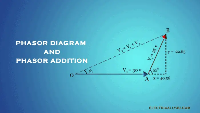
Phasor Diagram and Phasor Addition
What is RC Series Circuit? Phasor Diagram and Power Curve ... Steps to draw a Phasor Diagram The following steps are used to draw the phasor diagram of RC Series circuit Take the current I (r.m.s value) as a reference vector Voltage drop in resistance VR = IR is taken in phase with the current vector

Elt) Draw a phasor diagram to represent the current and ...
Phasor Diagram, How to draw a Phasor Diagram - YouTube Dear students this video is uploaded by Arvind Sharma.you can learn hear about engineering fundamentals and automotive parts,you can also learn that how the ...

Phasor diagram showing the amplitude modulation resulting ...
Phasor Diagrams - Learn About Electronics Five Rules for Drawing Phasor Diagrams. Rule 1. The length of the phasor is directly proportional to the amplitude of the wave depicted. Rule 2. In circuits which have combinations of L, C & R in SERIES (studied in AC Theory, Module 9) it is customary to draw the phasor representing CURRENT horizontally, and call this the REFERENCE phasor.
![No. 25] Constructing and reading the flux-weakening phasor ...](https://www.jmag-international.com/wp-content/uploads/engineers_diary/engineers_diary_025a.jpg)
No. 25] Constructing and reading the flux-weakening phasor ...
Excel Phasor Diagram Builder I found that I needed to draw phasor diagrams for some IEEE papers I was writing that would render properly when typeset. I've included another article on how to export a scalable vector diagram, but here I just wanted to talk about the program I wrote that creates the diagram in the first place. Previously I had simply used a drawing program (like PowerPoint or Inkscape), but I wanted a ...

Phasor Diagram and Phasor Algebra used in AC Circuits ...
How to draw PHASOR DIAGRAM of any AC circuit - YouTube Instructor : Haider AliElectrical and Electronic Engineering('16 batch)Bangladesh University of engineering and technology Our Facebook Page : ...
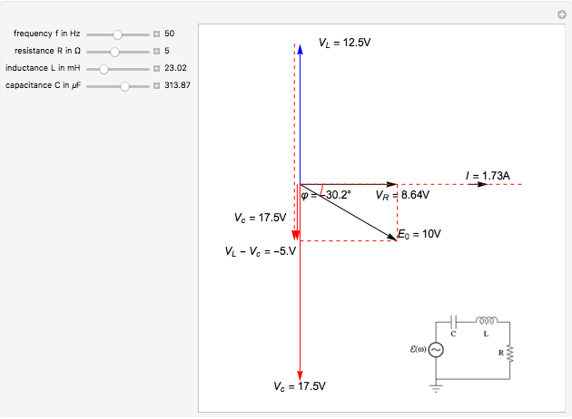
Phasor Diagram for Series RLC Circuits - Wolfram ...
How to draw phasor diagram for any circuit !! - YouTube This video provides a very easy concept of drawing phasor diagram for any complex network. concept of drawing phasor diagram for series and parallel R-L-C Ci...

Studying the Phasor Diagram
Phasor&Diagram&-Easy&"recipe"& Draw a vector with magnitude=E and makes an angle =ωt wrt the horizontal axis such that the horizontal component is Ecosωt. Draw a vector with magnitude=E and makes an angle =ωt+φ wrt the horizontal axis such that the horizontal component is Ecos(ωt+φ). Add these two vectors. The resultant vector
How to draw any phasor diagram easily - Quora
Note 3 How to Draw the Phasor Diagrams in MultiSim 1 ... How to Draw the Phasor Diagrams in MultiSim. 1. Working with the MultiSim program, RIGHT Click the circuit background and select Place Graphic. 2. Select LINE and draw the first line of your phasor diagram. 3. Repeat step 2 for the second line of your phasor diagram 4. Repeat step 2 above, except select TEXT (instead of line) and label your ...

Phasor - Wikipedia
Series RLC Circuit (Circuit & Phasor Diagram) | Electrical4U April 16, 2021 - NOTE: For remembering the phase relationship between voltage and current, learn this simple word called ‘CIVIL’, i.e in capacitor current leads voltage and voltage leads current in inductor. RLC Circuit For drawing the phasor diagram of series RLC circuit, follow these steps:
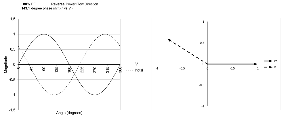
Solved Please draw the phasor diagram for a leading power ...
25 - AC circuits - Phasor diagrams - YouTube Introductory Physics - AC circuits - Phasor diagramswww.premedacademy.com
Solved Drawing of the phasor diagram. An example from | Chegg.com
How to draw a Phasor diagram – Learn.org.au How to draw a Phasor diagram. How to draw a phasor diagram for an RC AC series circuit. You must have a good knowledge of how a capacitor works to appreciate this. Oh, and if you do not appreciate this, QUIT NOW. The series RC circuit in AC is a fundamental building block. You MUST study the Floyd notes pages from the AC introduction with ...
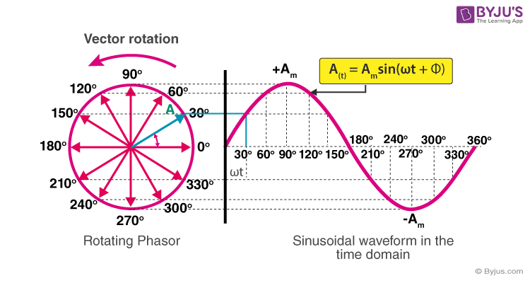
Phasor Representation Of AC Current And Voltage - BYJU'S
Phasor and The Phasor Diagram in AC Circuits Explained - YouTube In this video, phasor, and Phasor Diagram for AC circuits have been explained. And at the end, voltage and current relationship between the basic circuit ele...
Solved Draw the phasor diagram when there is a load | Chegg.com
Phasor Diagram of a Synchronous Generator - Electrical4U In order to draw the phasor diagram we will use V t as reference. Consider these two important points which are written below: We already know that if a machine is working as a synchronous generator then direction of I a will be in phase to that of the E f. Phasor E f is always ahead of V t.

Phasor Diagram - an overview | ScienceDirect Topics
Phasor Diagram - an overview | ScienceDirect Topics But we also display quantities ... space phasor manifests itself in the winding as a sinusoidally time-varying effect, the rate of change of which results in an induced voltage. For the diagrams to be meaningful, it hardly needs saying that all quantities of the same kind (e.g. voltages) must be drawn to the same ...

Phasor diagram of the negative-sequence components ...
How to draw a Phasor Diagram ? | Step by Step | Tech TALKS How to draw a Phasor Diagram of any Circuit is discussed here step by step.Subscribe my new channel here : ...
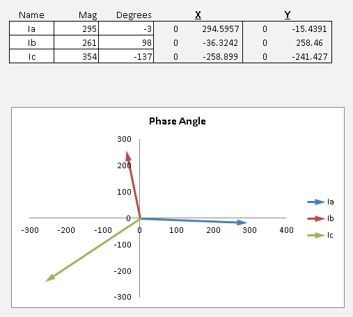
Excel Phasor Diagram Builder
Phasor Diagrams and Series Circuits Before drawing the phasor diagram let us consider certain facts about this circuit · The angle between the input voltage and the current is given by:

Series RLC Circuit (Circuit & Phasor Diagram) | Electrical4U
Electrical Phasor Diagrams - Electrical Academia To construct the phasor diagram, follow these steps: (Figure 4) Step 1. Draw the current phasor horizontally to the right as the reference phasor. Step 2. Draw the phasors for VA and VB to scale measuring the phase angles from the reference phasor using a protractor. Step 3. Construct the phasor parallelogram. Step 4.

Phasor Diagram and Phasor Algebra used in AC Circuits
AC Theory: How to Draw a Phasor Diagram for an Inductive Load to ... In this video we take the information from our fluorescent lamp experiment and use it to draw a phasor diagram to scale. An essential skill if you are studyi...
22.6 Phasor Diagrams
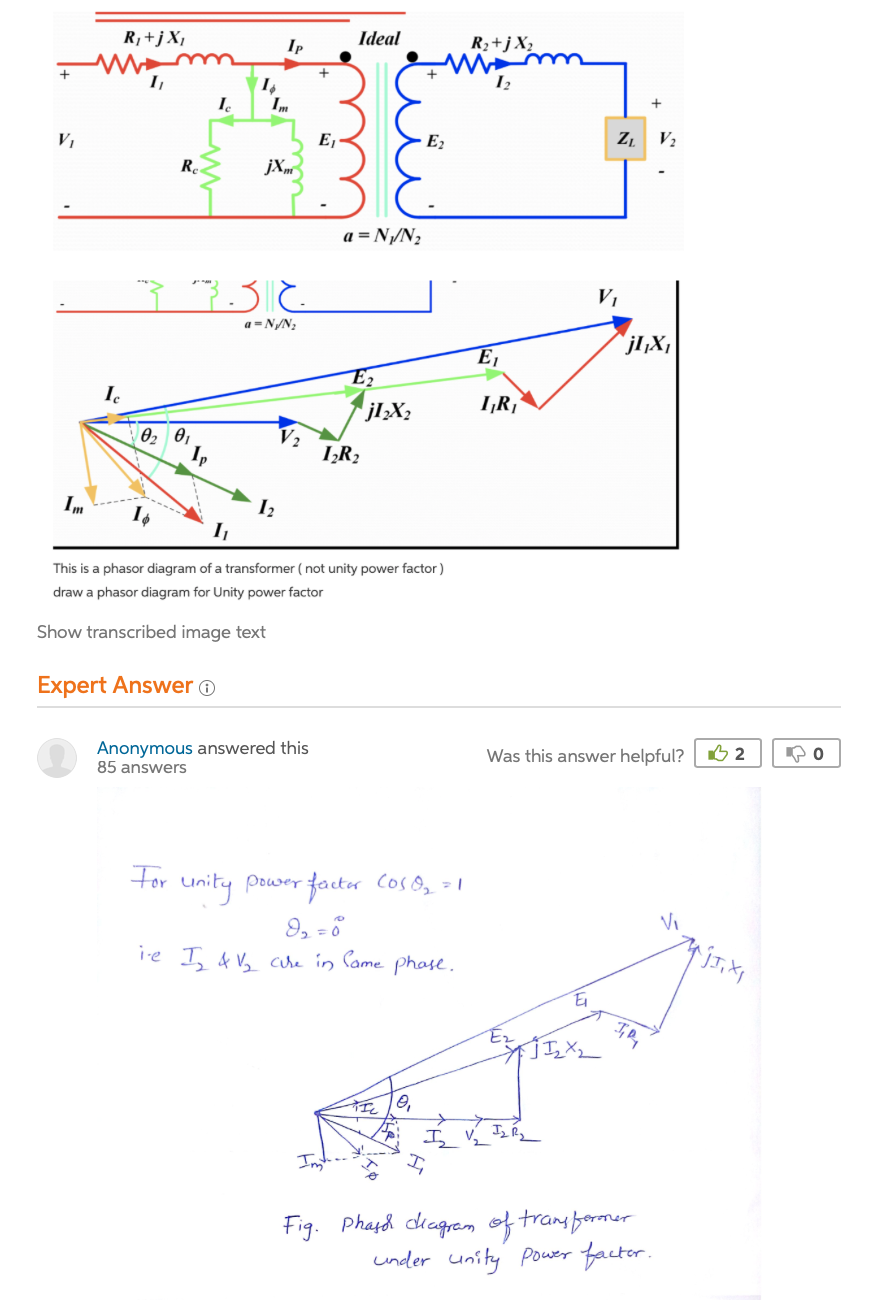
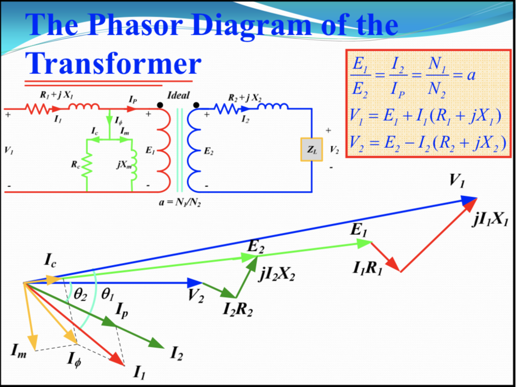
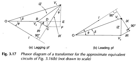
Phasor Diagram of Transformer - Electrical Concepts Phasor Diagram of Transformer for Lagging Load: When the transformer secondary is connected to an inductive load, the current flowing in the secondary winding is lagging w.r.t secondary terminal voltage. Let us assume that the current is lagging by an angle of ɵ2. Let, r1 = Primary winding Resistance. X1 = Primary winding leakage Reactance.
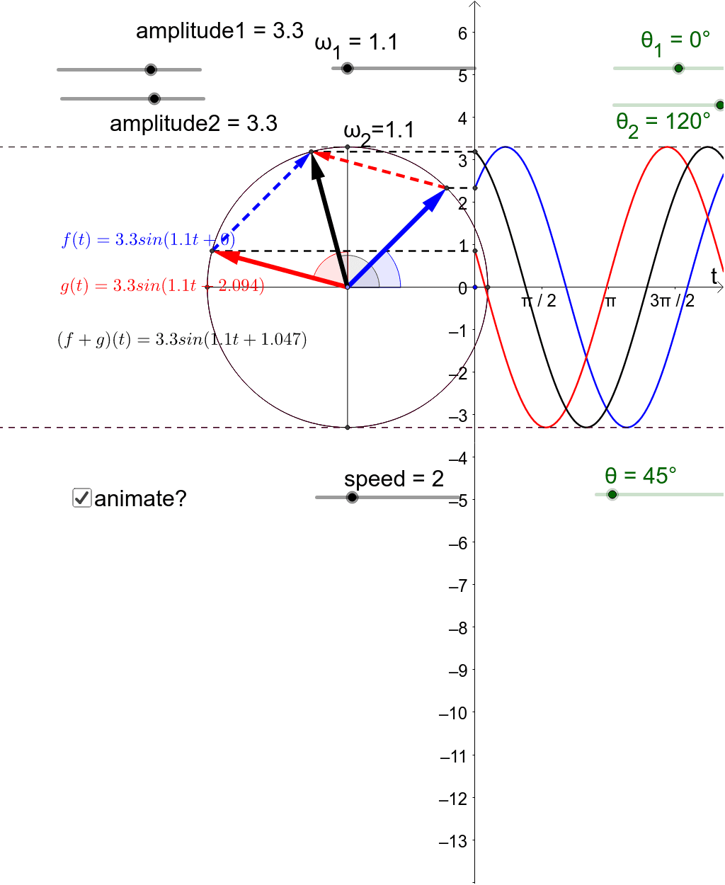
phasor diagram – GeoGebra
Phasor Diagram, How to draw a Phasor Diagram ...... - YouTube PHASOR DIAGRAMPhasor Diagram is a representation of Sinusoidal Voltage and Current.
Excel Phasor Diagram Builder
22.6 Phasor Diagrams The current iR through a resistor ... that on a phasor diagram by drawing a vector IR which lines up with the voltage VR. The current iC through a capacitor C is ahead of the voltage vC across the capacitor by 90 degrees so we may show that on a phasor diagram by drawing a ...

22.6 Phasor Diagrams
How to draw Phasor diagram for Electrical Circuits - Quora March 22, 2018 - Answer: A phasor diagram represents a rotating vector of two or more sinusoids of differing quantities and of the same frequency, at a single point in time, and illustrate the RMS values rather than the peak. The reference point or zero degrees is called the 'point of origin' and extends on the ...
How to draw Phasor diagram for Electrical Circuits - Quora
PDF TRANSFORMER PHASOR DIAGRAM - Electrical Concepts PHASOR DIAGRAM OF TRANSFORMER Prepared By ELECTRICALBABA.COM. IMPORTANT POINTS FOR PHASOR OF TRANSFORMER Transformer when excited at no load, only takes excitation current which leads the working Flux by Hystereticangleα. Excitation current is made up of two components, one

How to draw a Phasor diagram – Learn.org.au
Phasor Diagram and Phasor Algebra used in AC Circuits December 26, 2019 - The phasor diagram is drawn corresponding to time zero ( t = 0 ) on the horizontal axis. The lengths of the phasors are proportional to the values of the voltage, ( V ) and the current, ( I ) at the instant in time that the phasor diagram is drawn. The current phasor lags the voltage phasor ...

Phasor Diagram and Phasor Algebra used in AC Circuits
Phasor Diagram and Phasor Addition - Electrically 4 U Choose a phasor as a reference and draw it along the X-axis. Now, draw the other phasors at that instant, one after another. To get the resultant phasor, join the origin of the first phasor and the endpoint of the final phasor. Now, the length of the phasor from origin to the last point represents the magnitude of the resultant phasor.

Phasor Diagram - an overview | ScienceDirect Topics
PDF Phasors Final 3 9 2012 Ron Alexander.ppt - Aventri convenience, on the diagrams the phasor is al ways shown "fixed" for the given condition. •Phasor diagrams require a circuit di agram. The phasor diagram… has a indeterminate or vague meaning unless it is accompanied by a circuit diagram. •The assumed directions and polarities are not critic al, as the phasor diagram will confirm if the

Electrical Phasor Diagrams | Electrical Academia
Phasor Diagram of Transformer - EEEGUIDE.COM

Phasor diagrams and Impedances
HANDS-ON RELAY SCHOOL WSU – PULLMAN, WA. RON ALEXANDER - BPA

Phasor Diagram and Phasor Algebra used in AC Circuits
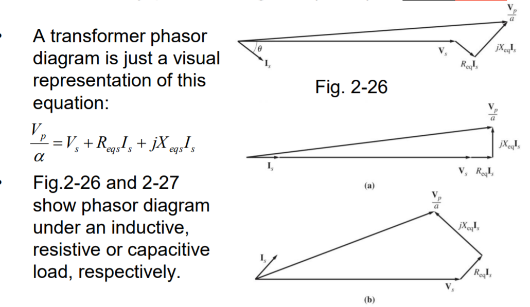
What is the transformer phasor diagram? - Quora

Phasor Diagram of Series RLC Circuit
0 Response to "35 how to draw phasor diagram"
Post a Comment