35 livewell timer wiring diagram
Timer Wiring Diagram Manual - Wiring Diagram and Schematic ... Operating instructions programmable timer switch e manualzz optimum op sbsw user pdf intermatic fm1stuzh 240u 21a 24 120 208 boat livewell installation tork rz307 timers digital lighting hager eh 010 instruction manual 2510sxt wiring diagram hydrotech sxt paragon 632 20 defrost eapl model a1d1 on power application clock and setting Grässlin Uk Ltd Installation Amp […] slots-casinospiele0.de › snobear-specs[email protected] - slots-casinospiele0.de 1 day ago · email protected] [email protected] Less than that 3/4 ton Diesel pulling it. SnoBear Specifications Overall Length - 208 lnches Body Width - 84.
Celebrities Archives - Hollywood.com Click to get the latest Celebrities content. Sign up for your weekly dose of feel-good entertainment and movie content!

Livewell timer wiring diagram
Livewell Pumps Diagrams For Boats - Wiring Diagrams Free Manuals or wiring diagrams would be especially useful! On the console you will find two(2) dials that operate the livewell pumps and one(1) that sets the timer mode. The pump dials are labelled "MAIN" and "AUX". SHURFLO BAIT SENTRY GPH Magnetic Drive Livewell Washdown Pump 12V Amp. SHURFLO's BAIT SENTRY is designed for easy installation ... 38 livewell timer module wiring diagram - Wiring Diagrams ... LIVEWELL TIMERS: OEM Livewell Timer Module Replacement timer module used by many OEM's for many year. Simply plugs into timer switch wiring harness. Can be used in new installations using an ON/OFF/ON switch Switch wiring diagram included. Item# 520 Availability: In-Stock Our Price: C$69.99 Automatic Livewell Pump Timer with variable output - YouTube Timer is available at
Livewell timer wiring diagram. Grasslin Timer Wiring Diagram Grasslin Timer Wiring Diagram. Grässlin UK Connect wiring in accordance with wiring diagram. Do not combine timer to control a load on a separate supply circuit, which can be a different. Wired incorrectly need wiring diagram. grasslin timer need to no what wires go were there are 4 wires coming out the timer red and brown together white and. Wiring Diagram For Ranger Bass Boat - Irish Connections 1978 Ranger V178 Electrial Diagram Boating Forum Iboats Forums. 10 basic rules for wiring a boat diagram electrical wires cable 1988 ranger 395v questions boats z520c 2016 3 battery of trolling motor livewell timer installation bass commanche 360v 18 ef johnson viking i just new 1995 trophy 2302 2017 rt 198p in replacing 4 pin connector on trailer 7 wire flat plug makeover step by electronics ... pasticceriadalfior.it › zhqexRunuo scripts - pasticceriadalfior.it Mar 05, 2022 · Serial number G 03905792. VRO is still there but disconnected. and Throttle Body then do the bolt up and re-tune for a 175. Johnson 85etlr77s. References Writer Bio150 hp Evinrude 1992-2005. suzuki motorcycle wiring diagrams classic cycles. i have a 1979 115 evinrude with compression numbers of 100, 100, 95 and 90. Boat Livewell Timer Installation fuse box with the red wire on the timer) the red wire on the top of the fuse box is tied directly to the battery and is the power feed for the entire fuse box. The red wire on the automatic livewell timer goes up through the wire harness and gets connected to a manual switch mounted somewhere on your
Connecting and configuring the Livewell pump timer 02/14 ... Timer can run the pump in on-off cycles or run the pump at lower duty. Variable Livewell Timer - New Wire Marine Variable Livewell Timer Wiring Diagram . Reviews There are no reviews yet. Be the first to review "Variable Livewell Timer" Cancel reply. You must be logged in to post a review. Related products. Timer Pod $ 48.00. Add to cart. Gift Card Rated 5.00 out of 5 $ 25.00 - $ 1,000.00. Options. Bluewater 40A Relay $ 22.00. Add to cart. Livewell Timer Wiring [Archive] - Walleye Message Central Walleye Message Central > Boats, Motors, Electronics and Trailers > Electronics > Livewell Timer Wiring. PDA. Livewell Timer Wiring. Kevin23. 06-22-2016, 04:29 PM. ... My job was to work with another guy to verify each wire and use a diagram and reconnect it as it was. Had to pull in some new wires as a few had shorts due to reciprocating saw ... Livewell Timer Module Wiring Diagram - autocardesign Livewell Timer Module Wiring Diagram - wiring diagram is a simplified within acceptable limits pictorial representation of an electrical circuit. It shows the components of the circuit as simplified shapes, and the power and signal friends in the midst of the devices.
Livewell Aerator Timers | Leisure Lectronics Livewell aerator timers & 12V dimmers for boats. Manufacturer of high-quality products for the marine industry, with over 30 years of experience designing and building electronic products for fishing and boating. N. Korea's parliamentary session | Yonhap News Agency 30.09.2021 · N. Korea's parliamentary session. This photo, released by North Korea's official Korean Central News Agency on Sept. 30, 2021, shows Kim Yo-jong, North Korean leader Kim Jong-un's sister and currently vice department director of the ruling Workers' Party's Central Committee, who was elected as a member of the State Affairs Commission, the country's … Livewell Timer | Livewell Timer Manufacturer Livewell Timer. We are one of the largest, fully integrated Livewell timer manufacturer in North America and have been servicing our customers for over 50-years. We are one of the largest supplier for Livewell timer for Marine industries and we manufacture this Timer in our Dallas, Texas facility and we provide one year warranty for all the Livewell timers. PDF 6002 Livewell Control Center Hook Up Diagram 6002 LIVEWELL CONTROL CENTER HOOK UP DIAGRAM Installation Select a location for mounting the Control Panel, cut a hole 1-7/8" x 1-5/8" (see sheet 2), secure panel with #8 sheet metal screws. After mounting panel, string wire to battery and pump areas. The RED wire connects to the Battery (+) positive, the BLACK wire connects to the Pump (-)
Buy Timer Delay Relay, AC 110V 120V Programmable Digital ...
saredumatsukiko.com › category › follower-episodeフォロワーさんの漫画 : され妻つきこブログ|アラサーママのサレ妻経験録 Powered by... Mar 09, 2022 · つきこ. 妊娠中に夫に不倫された経験を Instagramで投稿しています。 サレ妻さん向けの情報も発信中!

Trying to install digital timer to outside lights. Have two ...
Bass Tracker Boat Wiring Diagram - Wiring Diagram and ... Boat Livewell Timer Installation. Archive Electrical Systems Boat Design Net. Pro 170 Tracker Mod V Bass Boat. Tracker boats wiring diagram boat building standards basic trailer tacklereviewer 1985 bass with 150 merc the diagrams page 2 10 rules for a upgrading 175 electronics how to wire jon ignition switch troubleshooting fuse panel this old ...

Ranger 330v livewell timer wiring
Timer Switch Diagram - easywiring Livewell Timer Module Wiring Diagram wiring diagram is a simplified within acceptable limits pictorial representation of an electrical circuit. A wiring diagram usually gives guidance roughly the relative face and. 20 see pages 14 and 15 industrial duty door operator for other wiring configurations patent pending the maintenance alert system ...

Boat livewell timer repair. Livewell pump
PDF ProTimerTM / ProTimer Plus+TM Installation and Operation ... no water or fish are in livewell. TIMER - Set the switch in this position to activate and use the "Timed Delay" feature. MIN MAX ON TIMER OFF TIMED DELAY PUMP 1 2 3 Pump 12v Grnd Connect black wire to ground using supplied female connector. Connect 12v power supply using supplied female connector. Connect brown wire with supplied female ...

Amazon.com : Leisure Lectronics Automatic Livewell Timer ...
australiancar.reviews › Subaru_EJ20J_EngineSubaru EJ20J Engine - australiancar.reviews Subaru's EJ20J engine was a 2.0-litre, horizontally-opposed (or 'boxer') four-cylinder petrol engine. This article considers the naturally aspirated, EJ20J Phase I engine as it was supplied in Australian-delivered vehicles, including the 1997-98 Subaru SF Forester.

Wiring & Installing A Battery Monitor | SailNet Community
freispiele-cosmo690.de › procraft-dash-panel1988 procraft t. No matter what the reason, it's easy to make ... 1 day ago · Free P&P Free P&P. 1985 Procraft Boat Wiring Diagrams Schematics procraft bass boats forum, here is the boat wiring diagram with all of the dimensions in inches the rewire kit will plug directly into the 30 boat harness and will give all new wiring for the accessories on your boat we include adaptors for all of the components navigation lights ...

Livewell Fill/Aerate
PDF ProTimer/ProTimer Plus+ Installation and Operation ... the in the livewell. TIMER - Set the switch in this position to activate and use the TIMED DELAY feature. O TIME O TIMED DELAY PUMP MI MA Wiring Diagram for the ProTimer Plus+ BL-399-011121 1 2 3 Pump 12 Volt Grnd Connect black wire to ground using supplied female connector Connect 12 Volt power supply using supplied female connector Connect ...

Where to find replacement live well timer | Boating Forum ...
Amazon.com: livewell timer Leisure Lectronics Automatic Livewell Timer Aerator Pump 12V Module for Boat. 4.6 out of 5 stars. 45. $39.95. $39. . 95. Get it as soon as Sat, Mar 12. FREE Shipping by Amazon.

Leisure Lectronics 3-Position Livewell Timer Aerator Pump 12V ...
Livewell Timer Pod for Boat - New Wire Marine Product Description. This is a great little self-contained livewell timer pod for your boat. Very common on thousands of boats built in the last few decades. Marine-grade, and potted waterproof, this timer pod stands up to the harsh abuse and runs like a champ.. With very low failure rates and a pretty dang impressive current capacity (10A) - it's made for use as a boat aerator timer.

Leisure Lectronics 3-Position Livewell Timer Aerator Pump 12V ...
haptotherapie-west.nl › bayliner-hull-problemshaptotherapie-west.nl Mar 05, 2022 · Aerated livewell with timer. 0m sports bowider that's just the perfect size for bay cruising and mixed water sports. Sep 13, 2016 · Bayliner VR5 Bayliner Boats. Trophy was a Brunswick/Bayliner brand that they shut down in 2009 or so. 0 L Mercruiser Alpha I Stern Drive (220.
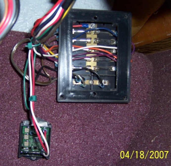
Livewell Timer Module wired up to Panel for test
Timer Switch Wiring Diagram - easywiring Livewell Timer Module Wiring Diagram wiring diagram is a simplified within acceptable limits pictorial representation of an electrical circuit. Grasslin Timer Wiring Diagram. After one minute of time duration the LED will automatically turn ON. Ah3 Delay Timer Wiring With Push Button Electrical Circuit Diagram Timer Basic Electrical Wiring
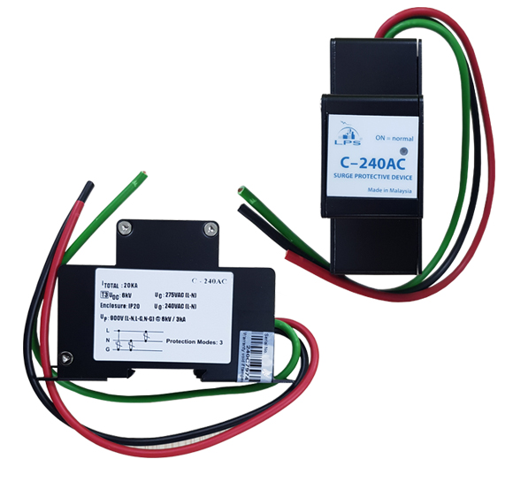
C-240AC - AC230 Surge Protector | MAGNET Security
Wiring Diagram for livewell pumps and bilge pump | Boating ... 4,292. Mar 3, 2012. #2. Re: Wiring Diagram for livewell pumps and bilge pump. Here is your bilge pump wiring. You'll notice two brown wires. The hot wire goes directly from the battery to the switch and then pigtails into the pump. The other brown wire goes to the float switch. This allows the bilge pump to run when the 3-way switch is put into ...

Amazon.com : Livewell Aerator Automatic Cycling Pump Timer ...
comparative cultural studies comparative literature media ... Issue 6.1 (March 2004) Thematic Issue: Shakespeare on Film in Asia and Hollywood. Ed. Charles S. Ross

Leisure Lectronics Automatic Livewell Timer Aerator Pump 12V ...
Skeeter Livewell Diagram - Wiring Diagram Pictures Skeeter Livewell Diagram. Thank you for choosing a Skeeter boat. This Owner's/Operator's manual contains information you will need for proper operation, maintenance, and care. Essentially, if you move far enough from the timer knob and switch, you only have a few wires. The switch setting for manual goes right to the pump lead (was a brown wire ...
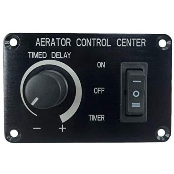
Pactrade Marine Boat Aerator Livewell Timer Switch Panel Adjustable Auto 12V 5A, This Automatic Aerator Control Pro Timer Plus Adjustable Livewell ...
Amazon.com: livewell timer switch ENERLITES Countdown Timer Switch for bathroom fans and household lights, 1-5-10-15-20-30 Min Settings with Manual Override, Always On Blue LED, Neutral Wire Required, UL Listed, HET06A-R-W, White. 4.6 out of 5 stars. 3,923.

Pimp my Livewell – Part 1: Livewell Wiring and Controls ...
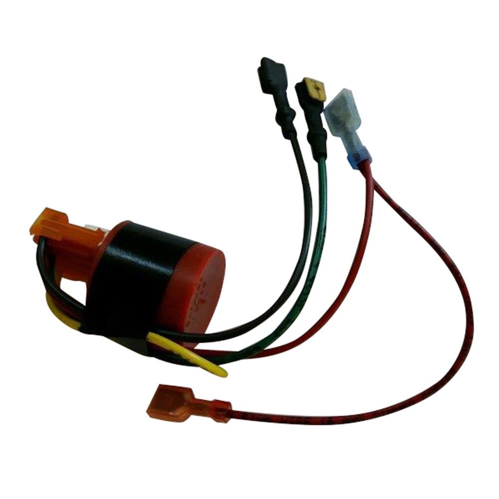
Rig Rite OEM Timer Module with Wires 520 - The Home Depot Variable Livewell Timer Variable Livewell Timer On cycle pumps for Variable Livewell Timer On cycle pumps for 30-seconds, Off cycle is variable from 0 to 5-1/2-minutes. Allows for continuous run for filling live well. Keeps bait or fish alive without draining battery down. 3 wire installation easily replaces your on off switch. 3/8 in. mounting hole for dashes up to 1 in. thick.

Buy Timer Delay Relay, AC 110V 120V Programmable Digital ...
Livewell Timer Wiring Diagram Database Livewell Timer Wiring Diagram from i0.wp.com Print the wiring diagram off in addition to use highlighters to trace the signal. When you make use of your finger or perhaps stick to the circuit with your eyes, it's easy to mistrace the circuit. 1 trick that We 2 to print a similar wiring picture off twice.

Pactrade Marine Boat Aerator Livewell Timer Switch Panel ...
mexpeters.nl 06.03.2022 · Auto/Manual livewell timer Jul 25, 2021 · Just mist a few squirts of the Old Salt Livewell Cleaner into the cooler or livewell either at the end of a day when it’s emptied or at the beginning of a day when heading out and before it’s filled with water and or fish. Get this live well here In many different sizes Amazon Affiliate Link https Video for Kodiak 26 gallon bait keeper/ …
Boat Livewell Timer Installation
Livewell Timer Wiring Diagram - schematron.org The timer Rewired the livewells using this diagram: Just a wiring tip. When I.This livewell timer is fully adjustable. The "On" cycle will run for Rig Rite Manufacturing Marine Automatic Livewell Timer by Rig Rite. by Rig Rite. $ $ 68 74 + $ shipping. Only 3 left in stock - order soon.

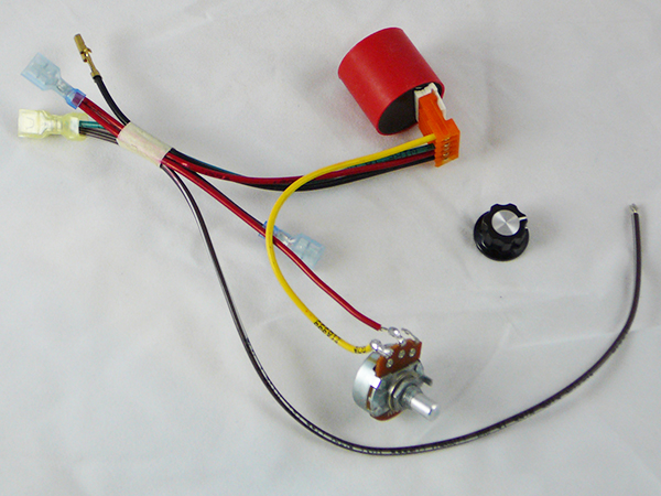
Variable Livewell Timer
Automatic Livewell Pump Timer with variable output - YouTube Timer is available at
RigRite® Variable Livewell Timer - 105268, Livewells & Bilge ...
38 livewell timer module wiring diagram - Wiring Diagrams ... LIVEWELL TIMERS: OEM Livewell Timer Module Replacement timer module used by many OEM's for many year. Simply plugs into timer switch wiring harness. Can be used in new installations using an ON/OFF/ON switch Switch wiring diagram included. Item# 520 Availability: In-Stock Our Price: C$69.99

Intermatic PF1000 Freeze Protection Control Parts | FWP-APS-PEP
Livewell Pumps Diagrams For Boats - Wiring Diagrams Free Manuals or wiring diagrams would be especially useful! On the console you will find two(2) dials that operate the livewell pumps and one(1) that sets the timer mode. The pump dials are labelled "MAIN" and "AUX". SHURFLO BAIT SENTRY GPH Magnetic Drive Livewell Washdown Pump 12V Amp. SHURFLO's BAIT SENTRY is designed for easy installation ...
Rig Rite OEM Timer Module with Wires in the RV Accessories ...

Honeywell Home ST699 Electronic Dual Zone Timer Installation ...

Livewell timer

Amcap Washing Machine Capacitor, Rs 60 /piece R.L. ...
Touch Pad Livewell Timer Help

NEW RANGER LOWE TRITON BOAT 4 WIRE FISHING BOAT AERATOR LIVEWELL TIMER.F/S. X1X | eBay

Livewell
Boat Livewell Timer Installation
Timers shop
electrical - 3-way smart-switch installation: How do I re ...
Timers shop

Livewell Timer help.

3-POSITION 12V Cycling Aerator Timer - Livewell Marine Switch ...
0 Response to "35 livewell timer wiring diagram"
Post a Comment