36 in a state transition diagram, the circle at the right with a hollow border is the initial state.
In UML 2 the name has been changed to State Machine Diagram. The following are the basic notational elements that can be used to make up a diagram: (1) Filled circle, pointing to the initial state. (2) Hollow circle containing a smaller filled circle, indicating the final state (if any). (3) Rounded rectangle, denoting a state. Click into the drawing area to start the selection frame; move the mouse to resize the selection frame; Release the mouse button to resize the selection frame
A UML state diagram also referred to as a state machine, holds information of an object with regards to the state the object is in and the transitions in between. By visualizing an object's behavior and its possible transitive states, a state diagram, also a statechart diagram gives you a better understanding of an object's behavior.
In a state transition diagram, the circle at the right with a hollow border is the initial state.
In a state transition diagram, the circle at the right with a hollow border is the initial state. false. A use case represents the steps in a specific business function or process. true. Just as objects are similar to adjectives, attributes resemble verbs that describe what and how an object does something. In a state transition diagram, the circle at the right with a hollow border is the initial state. False. A star marks the end of the lifeline. ... In a state transition diagram, the states appear as rounded rectangles with the state names inside. True. A black box wants and needs outside interference. False. A control is a specific member of a ... In a state transition diagram, the circle at the right with a hollow border is the initial state. True False. False. A class can belong to a more general category called a _____. a. catalog b. subclass c. register d. superclass. Superclass.
In a state transition diagram, the circle at the right with a hollow border is the initial state.. Full documentation can be found here.. defining an FSM. A finite-state machine or finite-state automaton is defined as a series of states and transitions between these states, driven by a sequence of inputs. The automaton begins at a start state, and proceeds through the transitions until it reaches an accept state.If given an input that isn't a valid transition, the automaton may either ... State Transition Diagram with example in software Jul 31, 2020 · When the software tester focus is to test the sequence of events that may occur in the system under test. Frequently Asked Questions (FAQ) In a state transition diagram, the circle at the right with a hollow border is the initial state. True/False. Answer: False. In a state ... In contrast to an initial state, which always has the same notation, a junction has always at least one incoming transition. ... Viewed from the outside the circle appears on the border of the corresponding state. In the inner view, transitions terminate or start at the circle (Figure 3.68). ... The state diagram specifies the formal parameter ... Method 1: Animating border. The most straightforward way to animate a border is… well, by animating border. .border-button { border: solid 5px #FC5185; transition: border-width 0.6s linear; } .border-button:hover { border-width: 10px; } Nice and simple, but there are some big performance issues. Since border takes up space in the document's ...
State Machine Diagrams. State machine diagram is a behavior diagram which shows discrete behavior of a part of designed system through finite state transitions. State machine diagrams can also be used to express the usage protocol of part of a system. Two kinds of state machines defined in UML 2.4 are . behavioral state machine, and; protocol state machine A final state is represented by a unfilled circle with an inner black-filled circle. Figure-01: Representation of initial, intermediate, and final states of a statechart diagram Intermediate states usually have two compartments, separated by a horizontal line, called the name compartment and internal transitions compartment . They are described ... Drawing Finite State Machines in LATEX using tikz A Tutorial Satyaki Sikdar ssikdar@nd.edu August 31, 2017 1 Introduction Paraphrasing from [beg14], LATEX (pronounced lay-tek) is an open-source, multiplatform document prepa- ration system for producing professional-looking documents, it is not a word processor. The advantage of using a node circle is that it defines a set of anchors that we can use them to get coordinates of the node border or to position nodes with accuracy with respect to given coordinates. By default, node center is positioned at the provided coordinates( (0,0) for the previous examples).
In a state transition diagram, the circle at the right with a hollow border is the initial state. 0..* The Unified Modeling Language (UML) notation _____ identifies a zero or many relation. superclass A class can belong to a more general category called a _____. methods. We have already seen the derivation of heat conduction equation for Cartesian coordinates. Now, consider a cylindrical differential element as shown in the figure. We can write down the equation in… When you pass the --desugar (⨻ experimental) switch, state-machine-cat will, before rendering, transform some pseudo states into transitions - see de-sugaring state machines for details.. Syntax highlighting. For editors supporting tree sitter (like atom): there's tree-sitter-smcat; The atom-state-machine-cat-preview plugin includes syntax highlighting for atom as well. Chapter 06 - Object Modeling 12. In a state transition diagram, the circle at the right with a hollow border is the initial state. a. True b. Fals e ANSWER: False RATIONALE: In a state transition diagram, the circle at the right with a hollow border is the final state. POINTS: 1 DIFFICULTY: Easy REFERENCES: 193 QUESTION TY PE: True / False HAS VARIABL ES: False LEARNING OB JECTIVES: SAD.12e.06 ...
Iopscience Iop Org
Looping a CSS Transition. The story of the transition is an epic tale of overcoming trials and tribulations. From being ignored by all the browsers to shamelessly having to carry around a vendor prefix to now near-universal acceptance, the journey sure was a bumpy one. Despite the great progress the transition property has made in the past few ...
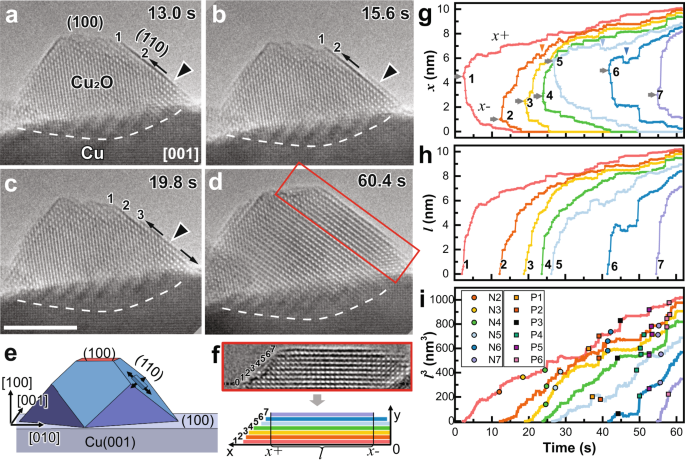
Unusual Layer By Layer Growth Of Epitaxial Oxide Islands During Cu Oxidation Nature Communications
In a state transition diagram, the circle at the right with a hollow border is the initial state. False. Your red Mustang is a(n) ____ of the CAR class. instance. After you identify the objects, classes, and relationships, you are ready to prepare an object relationship diagram that will provide an overview of the system.

Dynamic Wave Induced Settlement Behavior Of A Caisson Breakwater Built On A Sandy Seabed
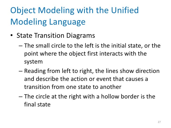
Object Modeling with the Unified Modeling Language • State Transition Diagrams - The small circle to the left is the initial state, or the point where the object first interacts with the system - Reading from left to right, the lines show direction and describe the action or event that causes a transition from one state to another - The ...

State Transition Diagram For A Markov Model The Circles Labeled State Download Scientific Diagram
In a state transition diagram, the circle at the right with a hollow border is the initial state. False. In a state transition diagram, the circle to the left is the final state. False. In a state transition diagram, the states appear as rounded rectangles with the state names inside.
1
Automata is the plural form of automaton, which means self-making in Greek. They are used to define abstract computing devices, or machines, in a theoretical platform. Probably you only heard of them if you are studying automata theory, or have a theory of computation course in your curriculum. They are represented with state diagrams.

A Sequence Diagram A Is A Dynamic Model Of A Use Case B Is Like A Blueprint For Course Hero
Work and energy in rotational motion are completely analogous to work and energy in translational motion, first presented in Uniform Circular Motion and Gravitation. Now, we solve one of the rotational kinematics equations for αθ. We start with the equation. ω2 = ωo2 + 2 αθ. Next, we solve for αθ: α θ = ω 2 − ω 0 2 2.
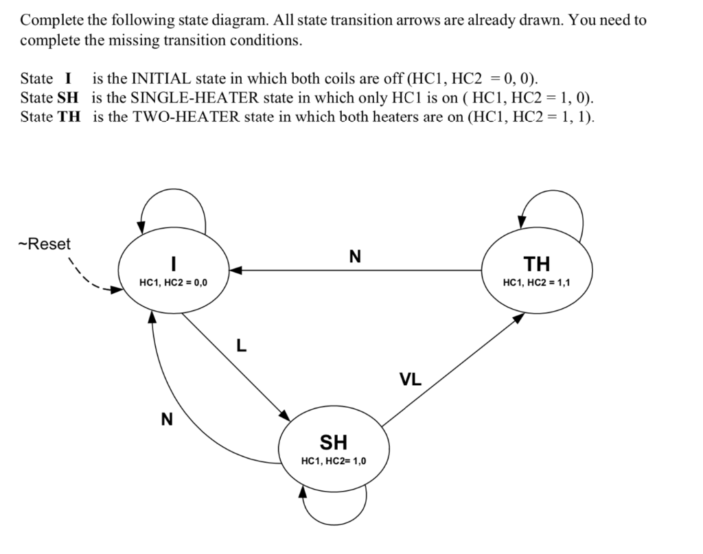
Complete The Following State Diagram All State Chegg Com
The diagram above is of four circles that overlap to show the connections between the different groups that the circles represent and they visually symbolize how they are all linked together. The circle to the right is coloured in and represents the Offender Circle as the following chapter will speak about treatment approaches for sexual offenders.

State Diagrams A State Diagram Is A Graph Whose Nodes Are States And Whose Directed Arcs Are Transitions Between States A State Diagram Specifies The Ppt Video Online Download
State In the state transition diagram, An object always remains in some state. Further, the state of the object may change after an event occur. Event Any activity that may trigger a state transition or can change the state. Guard In the state transition diagram, a guard is a boolean expression. Suppose if the guard is true, then it enables an event to trigger a transition. Transition The change of state within an object is represented with a transition. It is possible that an object changes its state when the transition occurs. Action One or more actions are taken by an object when the object changes a state.
Nanoengineering With Raft Polymers From Nanocomposite Design To Applications Polymer Chemistry Rsc Publishing
In a state transition diagram, the states appear as rounded rectangles with the state names inside. The small circle to the left is the initial state, or the point where the object first interacts with the system. 6. Reading from left to right, the lines show direction and describe the action or event that causes a transition from one state to ...
Solved Implement The State Diagram Shown Below With Three D Chegg Com
A) Yes, and it moves to the right. B) Yes, and it moves to the left. C) No, it remains in place. Left Right The initial momentum of the system is equal to zero and it must stay that way. The cart will move to the right at a tiny displacement in terms of the momentum of the ball to compensate for it and cancel it out.
1
In each region of the state machine or composite state it has at most a single transition to a vertex within the same region. An entry point is shown as a small circle on the border of the state machine diagram or composite state, with the name associated with it. Exit Point Exit point user exit.

The State Transition Diagram Of Wikitui Shapes With Dotted Lines Download Scientific Diagram
In a state transition diagram, the circle at the right with a hollow border is the initial state. True. In a state transition diagram, the states appear as rounded rectangles with the state names inside. actor. In a use case, an external entity, called a(n) _____, initiates a use case by requesting the system to perform a function or process. ...

Ra Pi Ne U 12 Against The Currents Of History The Early 12th C Bce Resurgence Of Tiryns Presses Universitaires De Louvain
In a state transition diagram, the circle at the right with a hollow border is the initial state. _____ ANS: F, final. 5. After you identify a system’s objects, classes, and relationships, you should develop a(n) object relationship diagram that provides an overview of the system. _____ ANS: T TRUE/FALSE. Share this link with a friend: ...

State Society And Markets In North Korea
State diagrams are an especially common method of documenting software design but they're not always easy to generate. If you have money, you can buy Visio and lay everything out manually. If you don't have money you can download Dia or some other free/open-source software to (hopefully) do the same work as Visio.
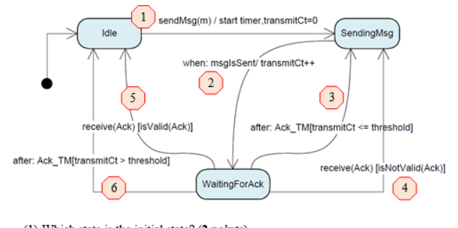
Solved The Following Is A Uml State Diagram 1 Which State Chegg Com
In a state transition diagram, the circle at the right with a hollow border is the initial state. True False. False. A class can belong to a more general category called a _____. a. catalog b. subclass c. register d. superclass. Superclass.

Big Homoclinic Orbit Bifurcation Underlying Post Inhibitory Rebound Spike And A Novel Threshold Curve Of A Neuron
In a state transition diagram, the circle at the right with a hollow border is the initial state. False. A star marks the end of the lifeline. ... In a state transition diagram, the states appear as rounded rectangles with the state names inside. True. A black box wants and needs outside interference. False. A control is a specific member of a ...
Chapter 06
In a state transition diagram, the circle at the right with a hollow border is the initial state. false. A use case represents the steps in a specific business function or process. true. Just as objects are similar to adjectives, attributes resemble verbs that describe what and how an object does something.
Broadband Chromatic Dispersion In Fiber Coupled Optical Interferometry

Plants Free Full Text Vitrification Ability Of Combined And Single Cryoprotective Agents Html
Cis2321 Test 6 Flashcards Quizlet
Feature Articles Archive Page 2 Of 82 Ecosystem Marketplace
Chapter Six Flashcards Quizlet

The Gains From Privatization In Transition Economies Is Change Of Ownership Enough In Imf Staff Papers Volume 2001 Issue 006 2002

A Comprehensive Study Of Structure And Properties Of Nanocrystalline Zinc Peroxide Sciencedirect
Ec Europa Eu

Solid Wikipedia
The Transitions Of Institutions Part Ii The Grand Pattern Of Development And The Transition Of Institutions
Psyarxiv Com

Object Modeling Chapter 06
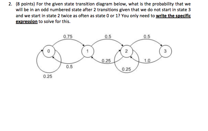
Solved 2 8 Points For The Given State Transition Diagram Chegg Com
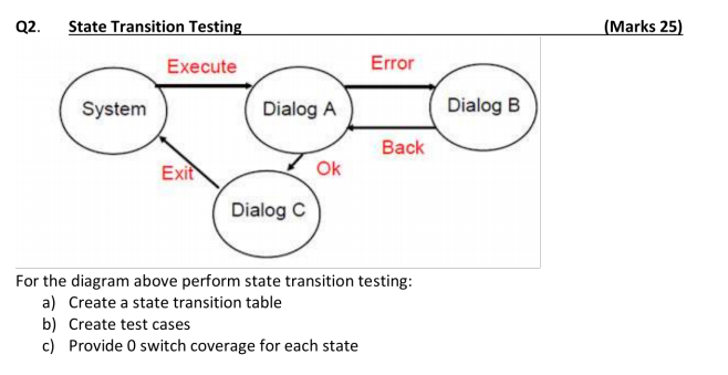
Solved Q2 State Transition Testing Marks 25 Execute Error Chegg Com

Eutectics Formation Properties And Applications Chemical Society Reviews Rsc Publishing

Clean Energy Transition Technologies And Innovations Report Cettir

Frontiers Fire And Its Interactions With Other Drivers Shape A Distinctive Semi Arid Mallee Ecosystem Ecology And Evolution
Pubs Rsc Org
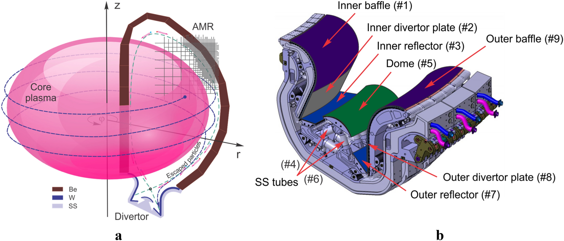
Potential Design Problems For Iter Fusion Device Scientific Reports
0 Response to "36 in a state transition diagram, the circle at the right with a hollow border is the initial state."
Post a Comment