34 vine thermostat wiring diagram
07.09.2018 07.09.2018 4 Comments on Qmark Heater Wiring Diagram to Figure 4 for wiring diagram. Note: Thermostat and control circuit wiring must be suitable to handle the full load of the heater (example MUH is rated Each heater has a wiring diagram affixed to the inside of the access door. Thermostat Wiring Diagrams for Heat Pumps - Heat Pump Thermostat Wire Diagrams. Heat pumps are different than air conditioners because a heat pump uses the process of refrigeration to heat and cool.While an air conditioner uses the process of refrigeration to only cool, the central air conditioner will usually be paired with a gas furnace, an electric furnace, or some other method of heating.
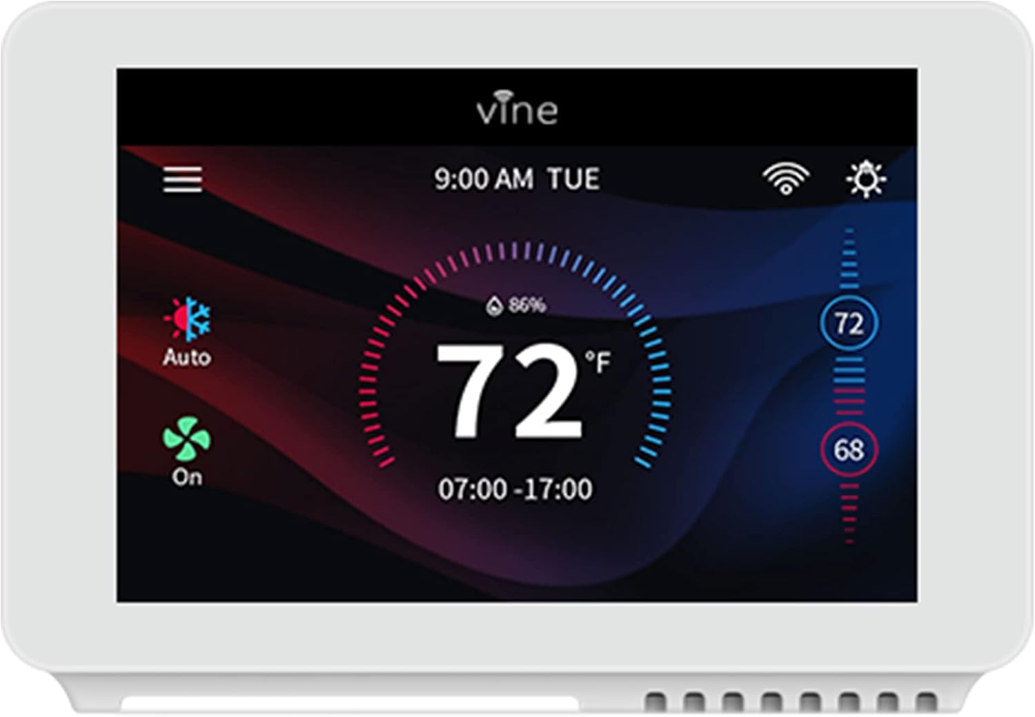
Energy costs will enable the Vine Smart WiFi Thermostat to pay for itself and you can save even more by purchasing the unit up front. Average consumers save approximately 23% annually off their energy bill. Support. Visit our website to explore an extensive library of videos, manuals, wiring diagrams, FAQ, and documentation.

Vine thermostat wiring diagram
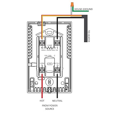
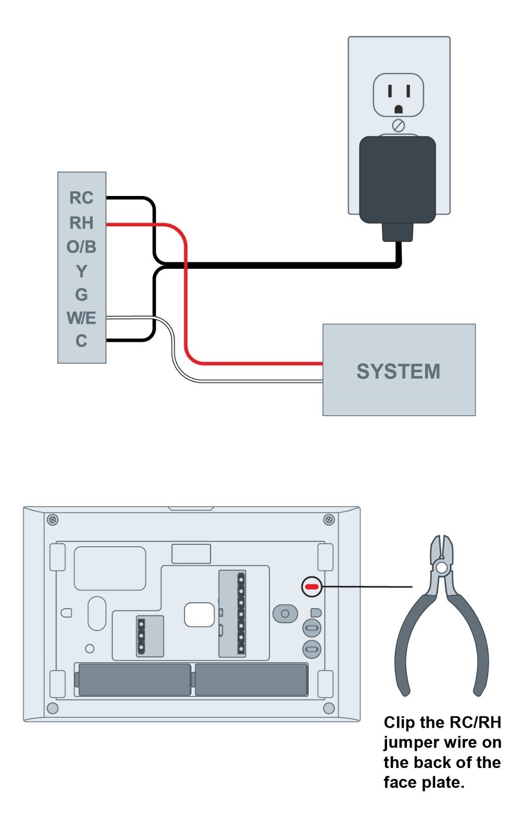
Conventional system without the C or spare wire (also commonly called a 4-wire system) 1) At the thermostat, connect C with the G wire; 2) At the furnace's wiring terminal, move the G wire to the C terminal, then use the included jumper wire to connect G with Y. 3) With this configuration the thermostat will have no fan control. Furnace terminal RC Vine Thermostat Wiring Diagram from www.forbbodiesonly.com. Print the wiring diagram off in addition to use highlighters in order to trace the circuit. When you use your finger or perhaps stick to the circuit with your eyes, it’s easy to mistrace the circuit. A single trick that We 2 to print out a similar wiring picture off twice. (also commonly called a 4-wire system) 1) At the thermostat, connect C with the G wire; 2) At the furnace's wiring terminal, move the G wire to the C terminal, then use the included jumper wire to connect G with Y For heating or cooling only systems, if you just have two wires (no C wire), you need to have a USB adapter to power the thermostat.
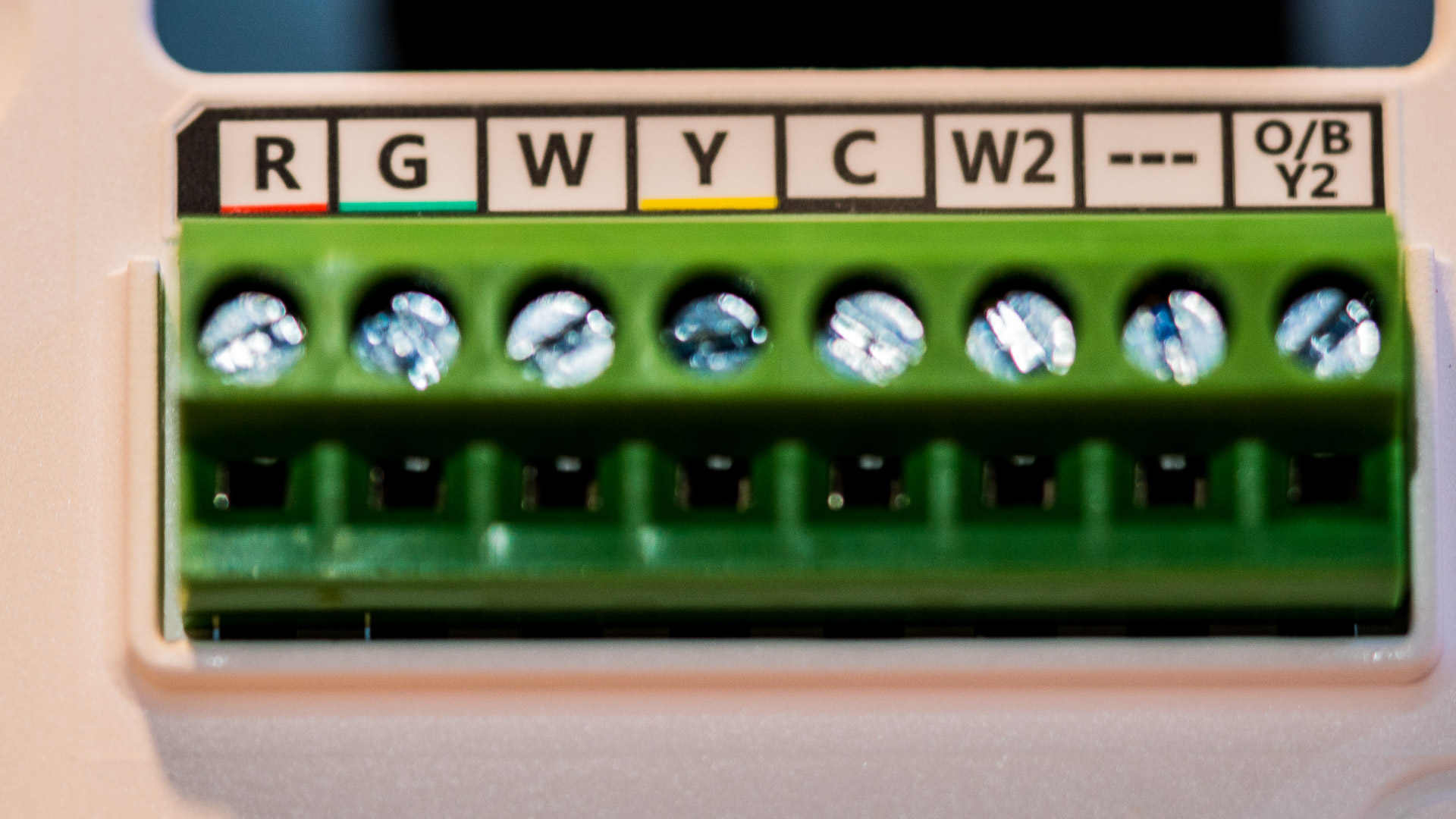
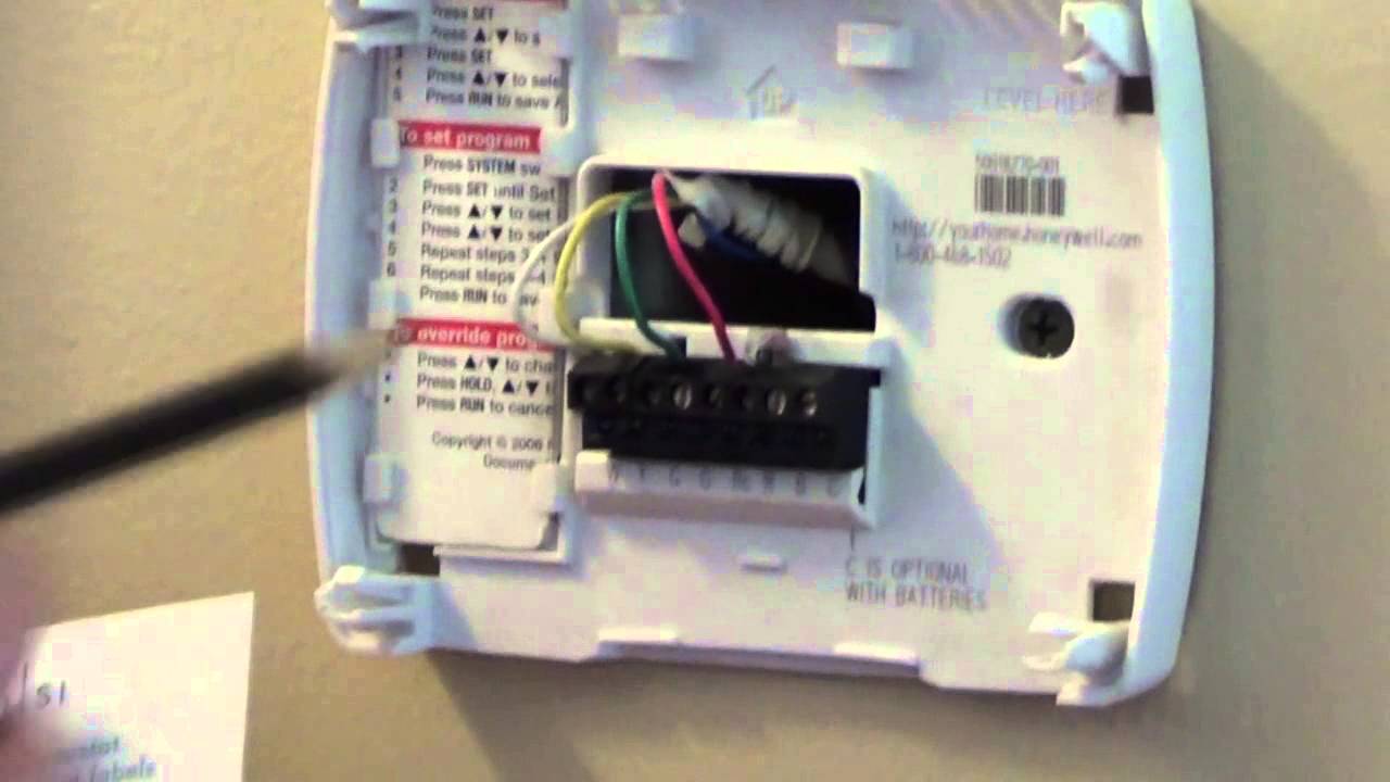
Vine thermostat wiring diagram. Look at the thermostat wiring photo you took. The following are wiring diagrams for common systems, please confirm you have a C connected to your old thermostat. Terminal RC RH C G Y Y2 W/E O/B/W2 Conventional System Power for cooling, 24V Power for heating, 24V Common wire, 24V Fan Power for cooling, 24V Power for heating, 24V Common wire ... Typically a thermostat wire pull is made to the air handler on split systems and then this wire is spliced for the separate wire pull which is made to the condenser. Some manufacturers put a terminal board strip near the control board in the air handler so a splice is not needed. Yellow for the Y2 terminal. • Your thermostat is a precise instrument Handle it with care • All wiring must conform to local codes and ordinances • This thermostat is designed for use with 4AA alkaline batteries and/or 24-volt AC C wire (or a 12- 24 AC or DC source) or millivolt gas systems Each thermostat relay load should be limited to 1 0 amp; higher amperage can Vine thermostat Wiring Diagram – wiring diagram is a simplified adequate pictorial representation of an electrical circuit. It shows the components of the circuit as simplified shapes, and the faculty and signal contacts together with the devices. A wiring diagram usually gives suggestion approximately the relative incline and concord of ...
(also commonly called a 4-wire system) 1) At the thermostat, connect C with the G wire; 2) At the furnace's wiring terminal, move the G wire to the C terminal, then use the included jumper wire to connect G with Y For heating or cooling only systems, if you just have two wires (no C wire), you need to have a USB adapter to power the thermostat. Vine Thermostat Wiring Diagram from www.forbbodiesonly.com. Print the wiring diagram off in addition to use highlighters in order to trace the circuit. When you use your finger or perhaps stick to the circuit with your eyes, it’s easy to mistrace the circuit. A single trick that We 2 to print out a similar wiring picture off twice. Conventional system without the C or spare wire (also commonly called a 4-wire system) 1) At the thermostat, connect C with the G wire; 2) At the furnace's wiring terminal, move the G wire to the C terminal, then use the included jumper wire to connect G with Y. 3) With this configuration the thermostat will have no fan control. Furnace terminal RC
4 Wire Installation Video Updated Youtube
Buy Vine Wi Fi 7day 8 Period Programmable Smart Home Thermostat Wi Fi Tj 919e Compatible With Alexa Google Assistant 5th Gen Online In Hungary B094n2kyb7
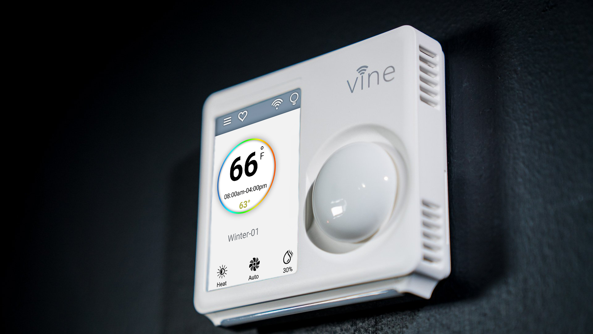
Vine Wi Fi Thermostat A Smart Device Without The Fluff

How To Install Thermostat Thermostat Installation Vine Smarthome

4 Wire Thermostat Wiring Color Code Onehoursmarthome Com

Best Wifi And Non Wifi Programmable Thermostat Reviews

Trane To Vine Thermostat Doityourself Com Community Forums

Mentkent Unduh Gratis Wiring Diagram Central Ac Ondol Penghangat Ruangan Sistem Pemanas Thermostat Lain Lain Gambar Png

Power Plant One Line Diagram Online Wiring Diagram Diagram Png Image Transparent Png Free Download On Seekpng

Download 25 Wiring Diagram For Central Ac Unit

How To Install A Wifi Thermostat Without A C Wire Updated Thermostastic

Thermostat Wiring Diagrams Quality Hvac Guides 101
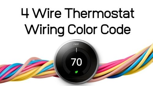
4 Wire Thermostat Wiring Color Code Onehoursmarthome Com

Wire Diagram For Taco Zone Valves For Hydronic Heating Systems
Buy Oj Microline Thermostat With Built In Gfci Uwg4 4999 Wifi Touch Screen Programmable Thermostat For Electric Radiant Floor Heating System Dual Sensing And Dual Voltage Capabilities Plus Floor Sensor Online In Slovakia B0873z1jwj

Amazon Com Ventamatic Xxfirestat 10 Amp Adjustable Programmable Thermostat With Firestat For Power Attic Ventilators Replacement Thermostat White Tools Home Improvement
Adding 24 Vac External Transformer In Place Of C Wire Sensi Us
1
Can I Pull A Common Wire Off An Evaporative Cooler Transformer Relay Home Improvement Stack Exchange
Yet Anther Newbie Installing A Humidifier

How To Install Thermostat Thermostat Installation Vine Smarthome

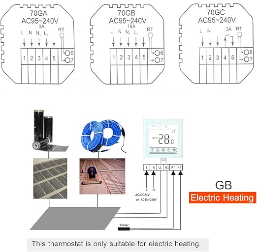
Amazon Com Smart Thermostat With Lcd Touching Screen 95 240v Ac Voice Temperature Controller Use For For Smart Home White Tools Home Improvement
Vineconnected Com
5 Wire Honeywell
Vine Wi Fi Thermostat A Smart Device Without The Fluff

Heat Pump Thermostat Wiring Thermostat Settings Vine Smarthome
Buy Vine Wi Fi 7day 8 Period Programmable Smart Home Thermostat Wi Fi Tj 919e Compatible With Alexa Google Assistant 5th Gen Online In Hungary B094n2kyb7
How To Wire A Sensi Thermostat Wifi Thermostat Youtube

Make My Wife Happy Thermostat Wiring Question Doityourself Com Community Forums

How To Install Thermostat Thermostat Installation Vine Smarthome

How To Install Thermostat Thermostat Installation Vine Smarthome
Thermostat Wiring Orange And Blue Wires Home Improvement Stack Exchange

Fhem Tablet Ui Thermostat Mobil Motor Terbaru Berita Review Panduan Membali Gambar Dan Lebih
Funien Tuya Wifi Smart Thermostat Programmable Temperature Controller For Water Gas Boiler Heating Compatible With Alexa Google Home Touch Screen With Backlight Amazon Com
0 Response to "34 vine thermostat wiring diagram"
Post a Comment