37 tie lines phase diagram
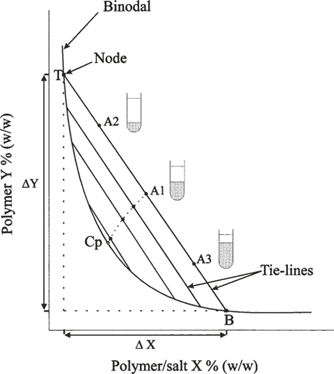
PDF Aqueous Chapter 5 Two-Phase Systems - Universidade de Aveiro the two-phase region (above the curve) from the single-phase region (below the curve). The composition of the phases in equilibrium are related by the tie-lines (TLs) that connect two points on the binodal curve, which correspond to the Fig. 5.1 Scheme of an orthogonal ternary phase diagram composed of component 1, PEH:Phase Diagrams - PetroWiki determine the fraction of each phase. The edges of the three-phase region are tie lines for the associated two-phase (2Φ) regions; thus, there is a two-phase region adjacent to each of the sides of the three-phase triangle. Three-phase regions can exist in several phase diagrams applied in the design of EOR processes.
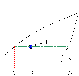
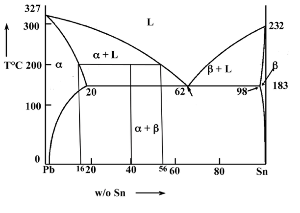
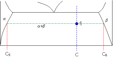
The lever rule - DoITPoMS The green dashed line below is an example of a tie-line. A tie-line is a horizontal (i.e., constant-temperature) line through the chosen point, which intersects the phase boundary lines on either side. Point 3. A tie-line is drawn through the point, and the lever rule is applied to identify the proportions of phases present. Intersection of the ...
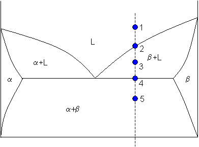
Tie lines phase diagram
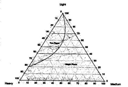
PDF PHASE RULE: TERNARY LIQUID SYSTEM References Phase rule: application to a two phase ternary system. Graphical representation and interpretation of a triangular phase diagram. Conjugate phases (solutions). Tie line. Distribution ratio. Objectives: Determination of the solubility limits in a ternary system of water and two other liquids, one of which is Ternary Phase Diagram - ScienceDirect Ternary phase diagrams are used to represent all possible mixtures of three solvents [1]; they are described in Chapter 3.Here, we shall indicate how they should be used to minimize the solvent consumption. Figure 2.1 (top) shows the methanol-chloroform-water ternary phase diagram with the tie-lines in the biphasic domain. Five particular compositions are shown in the diagram: Table 2.1 ... › pages › tutorialPiping & Instrumentation Diagrams Guide - Lucidchart Numbers are user assigned and schemes vary with some companies use of sequential numbering. Some tie the instrument number to the process line number. Others may choose to adopt unique and sometimes unusual numbering systems. The first letter defines the measured or initiating variables. Examples inlcude Analysis (A), Flow (F), Temperature (T ...
Tie lines phase diagram. 13.2: Phase Diagrams- Binary Systems - Chemistry LibreTexts Tie lines in the two-phase areas do not end at a vertical line for a pure solid component as they do in the system shown in the left-hand diagram. The three phases that can coexist at the eutectic temperature of \(\tx{1,052}\K\) are the melt of the eutectic composition and the two solid solutions. › support › articlesBeagle Protocol Analyzer User Manual - Total Phase In the data phase, the transmitter will send one data packet. For IN requests, the device may send a NAK or STALL packet during the data phase to indicate that it isnt able to service the token that it received. Finally, in the Handshake phase the receiver can send an ACK, NAK, or STALL indicating the success or failure of the transaction. PDF Chapter 9 Phase Diagrams - KSU 1. Locate composition and temperature in diagram . 2. In two phase region draw the tie line or isotherm . 3. Fraction of a phase is determined by taking the length of the tie line to the phase boundary for the other phase, and dividing by the total length of tie line . The lever rule is a mechanical analogy to the mass balance calculation. The ... › social › filesIntroduction to Power System Operation and Control - KTH Transmission lines 52 Lines . 33 Lines in 400kV, 17 Lines in 135kV . and 2 Lines in 220kV . Mitt. Loads 21 buses have loads connected to them . Generators 39 Generators . 23 Hydro stations, 15 Thermal Stations and 1 Synchronous compensator . 21 buses have generators . Shunts 22 buses have shunts connected . 3 buses have both shunt reactors and ...
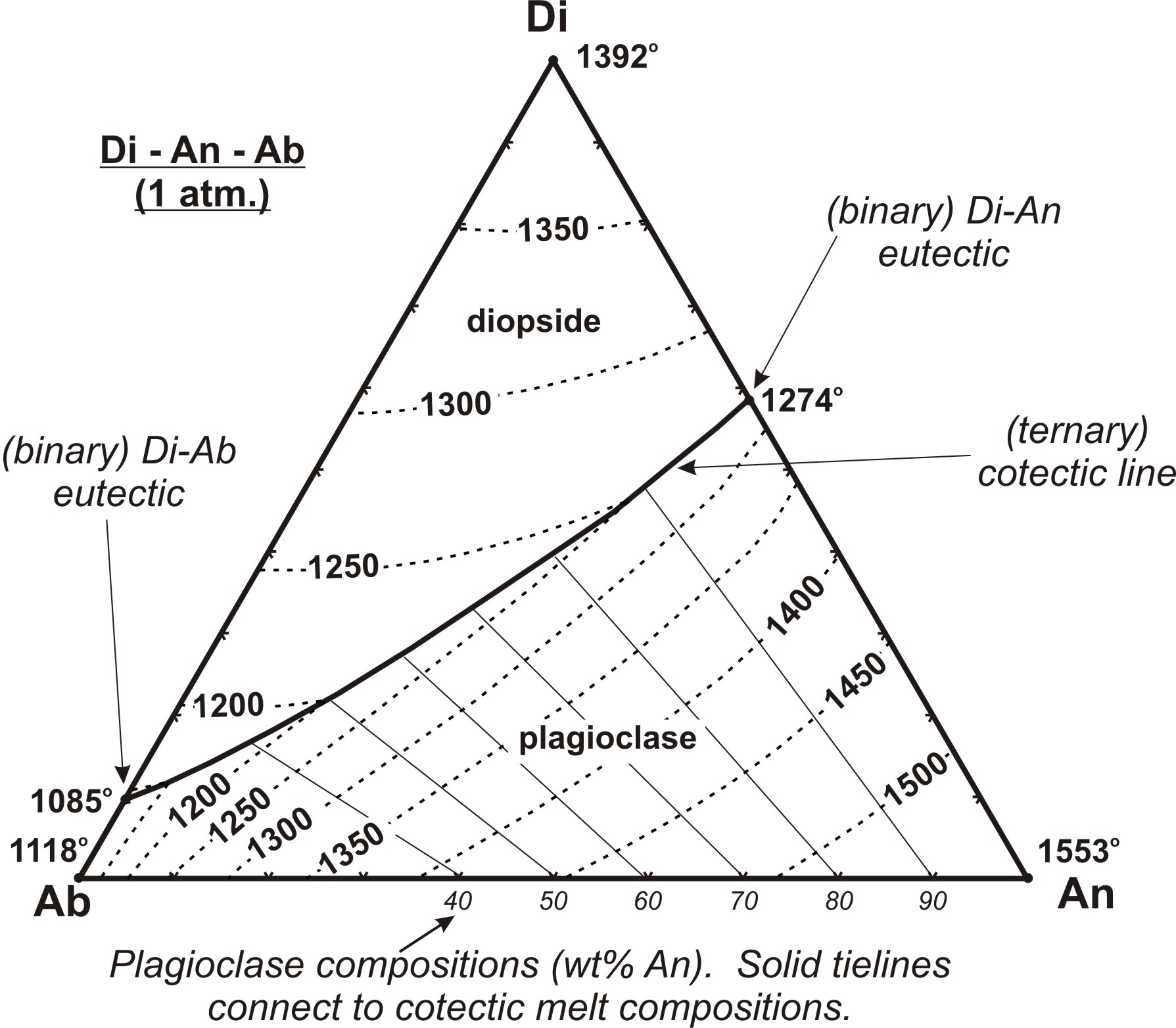
Interpolating Tie Lines on a Ternary Diagram - YouTube Organized by textbook: how to interpolate equilibrium tie lines on a ternary diagram. Made by faculty at the University of C... Triangular Plots in Metamorphic Petrology - Tulane University The tie lines divide the diagram into smaller compositional triangles, that tell us what minerals will coexist in a rock of any composition under the current temperature and pressure conditions. ... Still, in the ACF diagram, x plots within a 3 phase triangle. In the AFM diagram the same rock of composition x is seen to have garnet, staurolite ... en.wikipedia.org › wiki › Liquid–liquid_extractionLiquid–liquid extraction - Wikipedia Liquid–liquid extraction (LLE), also known as solvent extraction and partitioning, is a method to separate compounds or metal complexes, based on their relative solubilities in two different immiscible liquids, usually water (polar) and an organic solvent (non-polar). What is tie line in phase diagram? - FindAnyAnswer.com The tie lines determined in the two-liquid-phase coexistence region are found to be not parallel, suggesting that the dominant mechanism of lipid phase separation in this region changes with the membrane composition. We provide a phase diagram of the DOPC/eSM/Chol mixture and predict the location of the critical point.
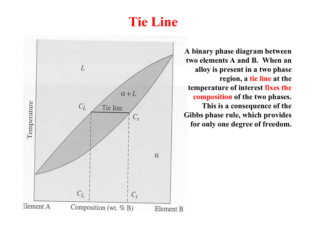
en.wikipedia.org › wiki › DiagramDiagram - Wikipedia visual information device : Like the term "illustration", "diagram" is used as a collective term standing for the whole class of technical genres, including graphs, technical drawings and tables. specific kind of visual display : This is the genre that shows qualitative data with shapes that are connected by lines, arrows, or other visual links. What is tie line in chemistry? - AskingLot.com Tie lines connect compositions of liquid and vapor phases in equilibrium. What is 3phase diagram? Three Phase Diagram: A soil mass consist of the solid particles and the voids in between them. So there is a three phase system, but when the voids are only filled with air, or only filled with water then soil becomes a two phase system. PDF Chapter 9: Phase Diagrams - Florida International University in 2-phase region: 1. Draw the tie line. 2. Note where the tie line intersects the liquidus and solidus lines (i.e. where the tie line crosses the phase boundaries). 3. Read off the composition at the boundaries: Liquid is composed of CL amount of Ni (31.5 wt% Ni). Solid is composed of Cαααα amount of Ni (42.5 wt% Ni). Phase diagram and tie-line determination for the ternary ... The tie lines determined in the two-liquid-phase coexistence region are found to be not parallel, suggesting that the dominant mechanism of lipid phase separation in this region changes with the membrane composition. We provide a phase diagram of the DOPC/eSM/Chol mixture and predict the location of the critical point.
How to Construct Ternary Diagram? | Alloys | Metallurgy The line SL can be used as a tie line to know the amounts of these phases such as: Types of Derived Two Dimensional Diagrams from Ternary Diagrams: ... The Fig. 3.61 (a) is a ternary three dimensional phase diagram of metals, each having partial solid solubility in the other. Fig. 3.61 (b) is the liquidus plot with temperature contours, while ...
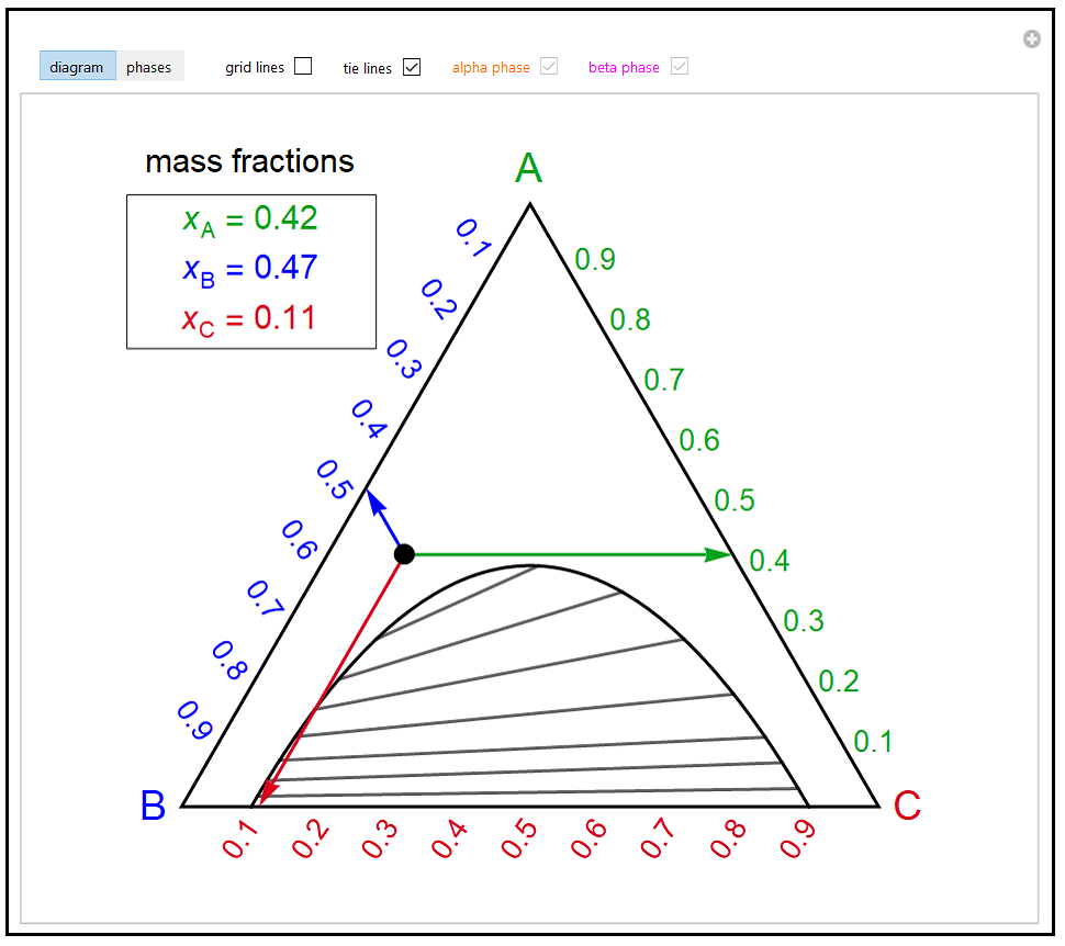
demonstrations.wolfram.com › BasicTernaryPhaseDiagramBasic Ternary Phase Diagram - Wolfram Demonstrations Project This Demonstration shows two representations of a ternary phase diagram which is used to represent the phase behavior of three-component mixtures. Move the black dot to any location within the triangle by clicking on that location which represents the overall composition of the mixture. Each corner of the triangle corresponds to a pure component. The mass fraction of a component in the mixture i;
Ternary phase diagrams - PetroWiki As Fig. 3 shows, at 1,000 psia the two-phase region is a band that stretches from the C 1 -C 10 side of the diagram to the tie line on the C 1 -C 4 side. If the pressure is increased above 1,000 psia, the liquid composition line shifts to higher methane concentrations; methane is more soluble in both C 4 and C 10 at the higher pressure (see Fig. 4).The two-phase region detaches from the C ...
Tie Lines from a Conjugate Curve in Ternary LLE Diagram For temperatures above , this ternary system gives a type I liquid-liquid equilibrium (LLE) diagram. The Demonstration uses arc-length continuation to compute the LLE diagram. In addition, the conjugate curve (shown in green) is superimposed on the same diagram. As you choose a point on the conjugate curve by dragging the slider, the ...
Lecture 5: Binary Phase Diagrams, Lens Diagram, Common ... Lever rule, tie lines, common tangents, and 2 phase equilibrium are discussed.
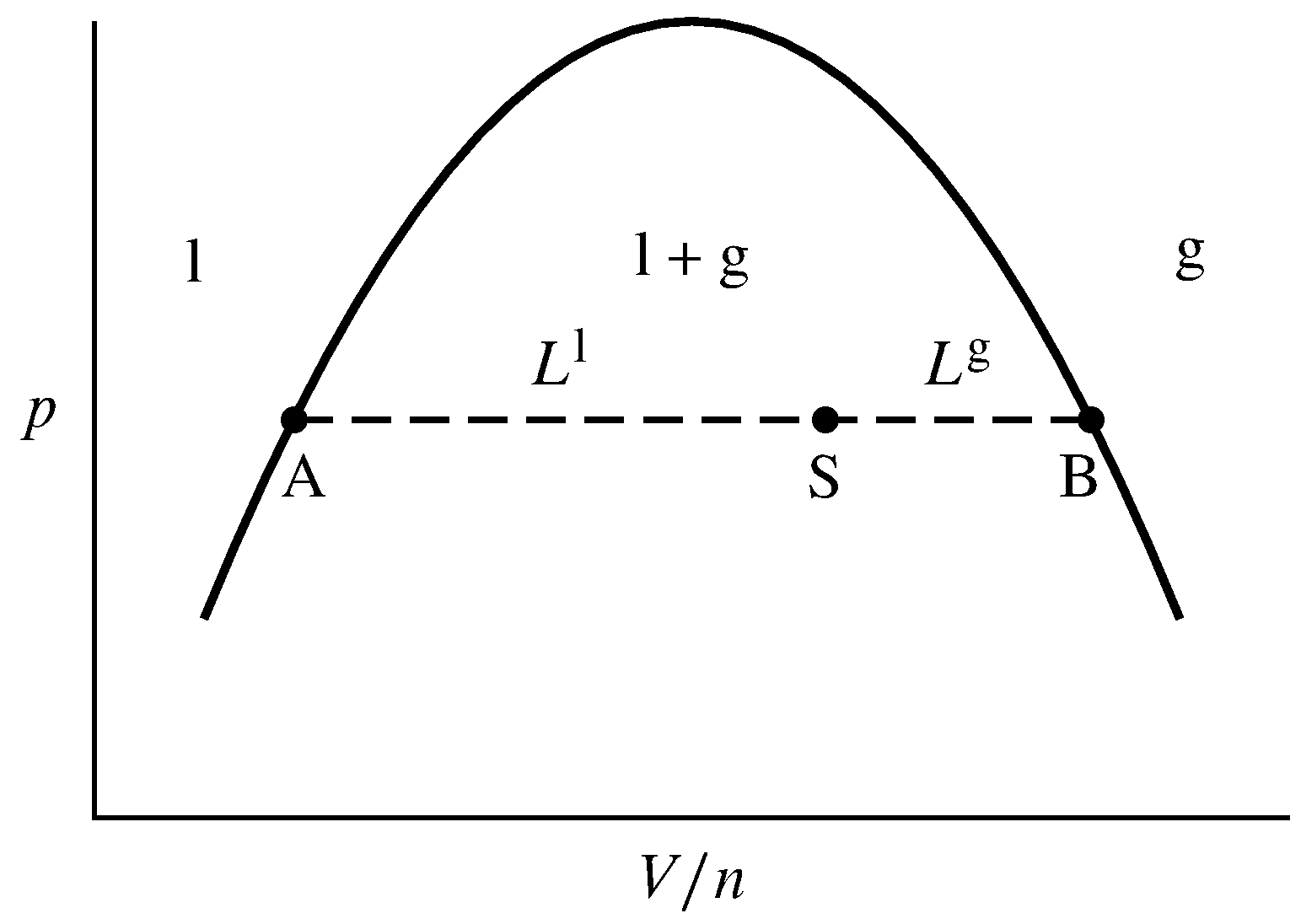
FEC: Pxy (Phase) Diagrams - University of Pittsburgh Tie lines are the name given to lines that bridge the "coexistence space" in a phase diagram. In the example above the lens-shaped region between the line and the curve is a "no mans land" that separates the vapor phase compositions from the liquid phase compositions. The bi-colored line is an example of a tie line.
Interactive Exploration of High-Dimensional Phase Diagrams Phase diagrams for more than 2 components traditionally include tie-lines to clarify which phases are in equilibrium. For a generic 3-dimensional cross-section in an n-dimensional (\(n>3\)) space, the probability that a tie-line lies exactly in the subspace of the chosen cross-section is negligible. Although this would suggest that tie-lines ...
How to draw tie-lines in a ternary alloy ... - ResearchGate Suppose the point of interest is D. Draw lines from points the corners (A,B,C) through D to the opposite side. Say they intersect the sides at E,F,G respectively. Now you can use a lever-rule type ...
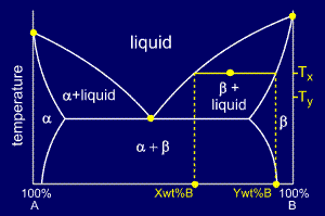
Tie Lines and the Lever Rule An isothermal (constant temperature) line through the alloy's position on the phase diagram when it is in a two phase field, intersecting the two adjacent solubility curves, is called a tie line (yes, that's the horizontal yellow line on the diagram).. The ends of the tie lines show the compositions of the two phases that exist in equilibrium with each other at this temperature.
PDF Phase Diagram and Tie-Line ... - Max Planck Society The tie lines determined in the two-liquid-phase coexistence region are found to be not parallel, suggesting that the dominant mechanism of lipid phase separation in this region changes with the membrane composition. We provide a phase diagram of the DOPC/eSM/Chol mixture and predict the location of the critical point.
Different Kinds of Reactions - Teaching Phase Equilibria Classic examples are the reactions among the aluminum silicates (kyanite-sillimanite-andalusite; see the photomicrograph and phase diagram shown at right), the conversion of graphite to diamond at high pressure, and calcium carbonate (calcite-aragonite) equilibria. Most solid-solid reactions plot on a P-T diagram as essentially straight lines.
PDF Chapter Outline: Phase Diagrams 1. Locate composition and temperature in diagram 2. In two phase region draw the tie line or isotherm 3. Fraction of a phase is determined by taking the length of the tie line to the phase boundary for the other phase, and dividing by the total length of tie line The lever rule is a mechanical analogy to the mass balance calculation.
Chapter 8 Phase Diagrams - Central Michigan University The tie line indicates the phase boundaries at x N = 0.35 and x N = 0.83 (the compositions of the two liquid phases). ... 8.6 Liquid-solid phase diagram . Consider the two-component liquid of composition a 1 in the diagram above. The changes can be described as follows: ...
What is tie line in phase diagram? The tie lines determined in the two-liquid-phase coexistence region are found to be not parallel, suggesting that the dominant mechanism of lipid phase separation in this region changes with the membrane composition. We provide a phase diagram of the DOPC/eSM/Chol mixture and predict the location of the critical point.
Lever rule Binary phase diagrams. Before any calculations can be made, a tie line is drawn on the phase diagram to determine the mass fraction of each element; on the phase diagram to the right it is line segment LS. This tie line is drawn horizontally at the composition's temperature from one phase to another (here the liquid to the solid).
Phase Diagram: Meaning and Types - Engineering Notes India Meaning of Phase Diagram 2. Type of Phase Diagram 3. Various Type of Phase Diagram Reaction 4. Congruent Phase Transformations 5. Influence of Alloying Elements. ... If the entire length of the tie line mo is taken to represent 100% or the total weight of the two phases present at temperature T, the lever rule may be expressed mathematically as
Orientation of Tie-Lines in the Phase Diagram of DOPC/DPPC ... by P Uppamoochikkal · 2010 · Cited by 85 — We report the direction of tie-lines of coexisting phases in a ternary diagram of DOPC/DPPC/cholesterol lipid.6 pages
Ternary Phase diagrams A Ternary Phase Diagram shows the phases of a three component system. Normally, we represent these phases in a triangular diagram where the apices of the triangle represent the three pure components and the distance from an apex is a measure of it's concentration. ... Note that the tie-lines joining the two phases in the two-phase region are ...
› RakeshSingh125 › fe-cdiagramFe-C diagram - SlideShare Nov 18, 2013 · 1. The Iron–Carbon Phase Diagram Prof. H. K. Khaira Professor in MSME Deptt. MANIT, Bhopal 2. Iron–Carbon Phase Diagram • In their simplest form, steels are alloys of Iron (Fe) and Carbon (C). • The Fe-C phase diagram is a fairly complex one, but we will only consider the steel and cast iron part of the diagram, up to 6.67% Carbon. 3.
› pages › tutorialPiping & Instrumentation Diagrams Guide - Lucidchart Numbers are user assigned and schemes vary with some companies use of sequential numbering. Some tie the instrument number to the process line number. Others may choose to adopt unique and sometimes unusual numbering systems. The first letter defines the measured or initiating variables. Examples inlcude Analysis (A), Flow (F), Temperature (T ...
Ternary Phase Diagram - ScienceDirect Ternary phase diagrams are used to represent all possible mixtures of three solvents [1]; they are described in Chapter 3.Here, we shall indicate how they should be used to minimize the solvent consumption. Figure 2.1 (top) shows the methanol-chloroform-water ternary phase diagram with the tie-lines in the biphasic domain. Five particular compositions are shown in the diagram: Table 2.1 ...
PDF PHASE RULE: TERNARY LIQUID SYSTEM References Phase rule: application to a two phase ternary system. Graphical representation and interpretation of a triangular phase diagram. Conjugate phases (solutions). Tie line. Distribution ratio. Objectives: Determination of the solubility limits in a ternary system of water and two other liquids, one of which is
![PDF] Phase diagram and tie-line determination for the ternary ...](https://d3i71xaburhd42.cloudfront.net/725aa4be1c0fd7cf111062971888c2215e4ae6b7/5-Figure4-1.png)


![PDF] Phase diagram and tie-line determination for the ternary ...](https://d3i71xaburhd42.cloudfront.net/725aa4be1c0fd7cf111062971888c2215e4ae6b7/6-Figure5-1.png)







0 Response to "37 tie lines phase diagram"
Post a Comment