38 fe ni phase diagram
Decomposition of Fe-Ni martensite: Implications for the ... The low-temperature (<500 C) decomposition of Fe-Ni martensite was studied by aging martensitic Fe-Ni alloys at temperatures between 300 C and 450 C and by measuring the composition of the matrix and precipitate phases using the analytical electron microscope (AEM). Fe-Ni system: thermodynamic modelling assisted by atomistic ... Fe-Ni phase diagram has been studied for more than a century. ... Atomistic calculations may complement experimental investigation of phase equilibria and ...1 page
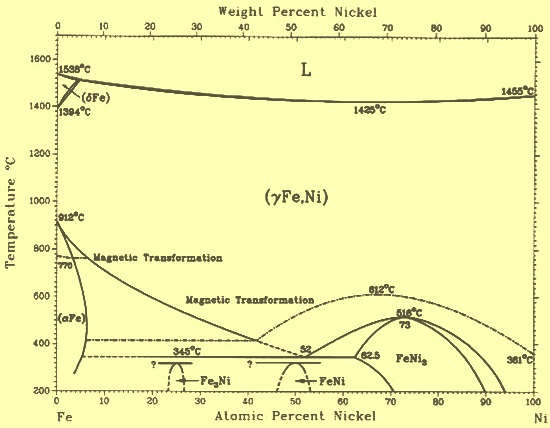
PDF I i FE-NI PHASE DIAGRAM - NASA b t m 0 v 1' Fe-Ni Phase Diagram u. T-r I. Guidstein and R. E. Ogilvie ABSTRACT The CY and y solubility limits in the Fe-Ni phase diagram have been redetermined at temperatures above 500OC. couple and a quench-and-annea technique were used. limits were measured with an electron probe microanalyzer.
Fe ni phase diagram
Fe-Ni Phase Diagram on Vimeo This can be directly understood from the Fe-Ni phase diagram: all metal is liquid above ca. 1500ºC. A solid solution crystallises below this temperature - gamma-Fe. This gamma-Fe decomposes below ca. 500-700ºC and depending on Ni-concentration into alpha-Fe (kamacite) and gamma-Fe (taenite). Hollow carbon sphere encapsulated nickel nanoreactor for ... As green chemistry, aqueous-phase reactions play a vital role in modern fine chemical synthesis. Herein, an encapsulated nickel in a hollow carbon sphere ([email protected]) catalyst was constructed to effectively catalyze an aqueous-phase hydrogenation-rearrangement tandem (AP-HRT) reaction, in which water was employed as the solvent and reactant simultaneously. › potentials › systemFe-Ni - NIST Oct 05, 2010 · The L12-Ni3Fe compound has the largest negative formation energy, which is consistent with the experimental Fe–Ni phase diagram. The L10–FeNi compound has also been observed experimentally in meteorite samples as a metastable phase. It is suggested here that the C11f compounds could also form in Fe–Ni alloys at low temperatures.
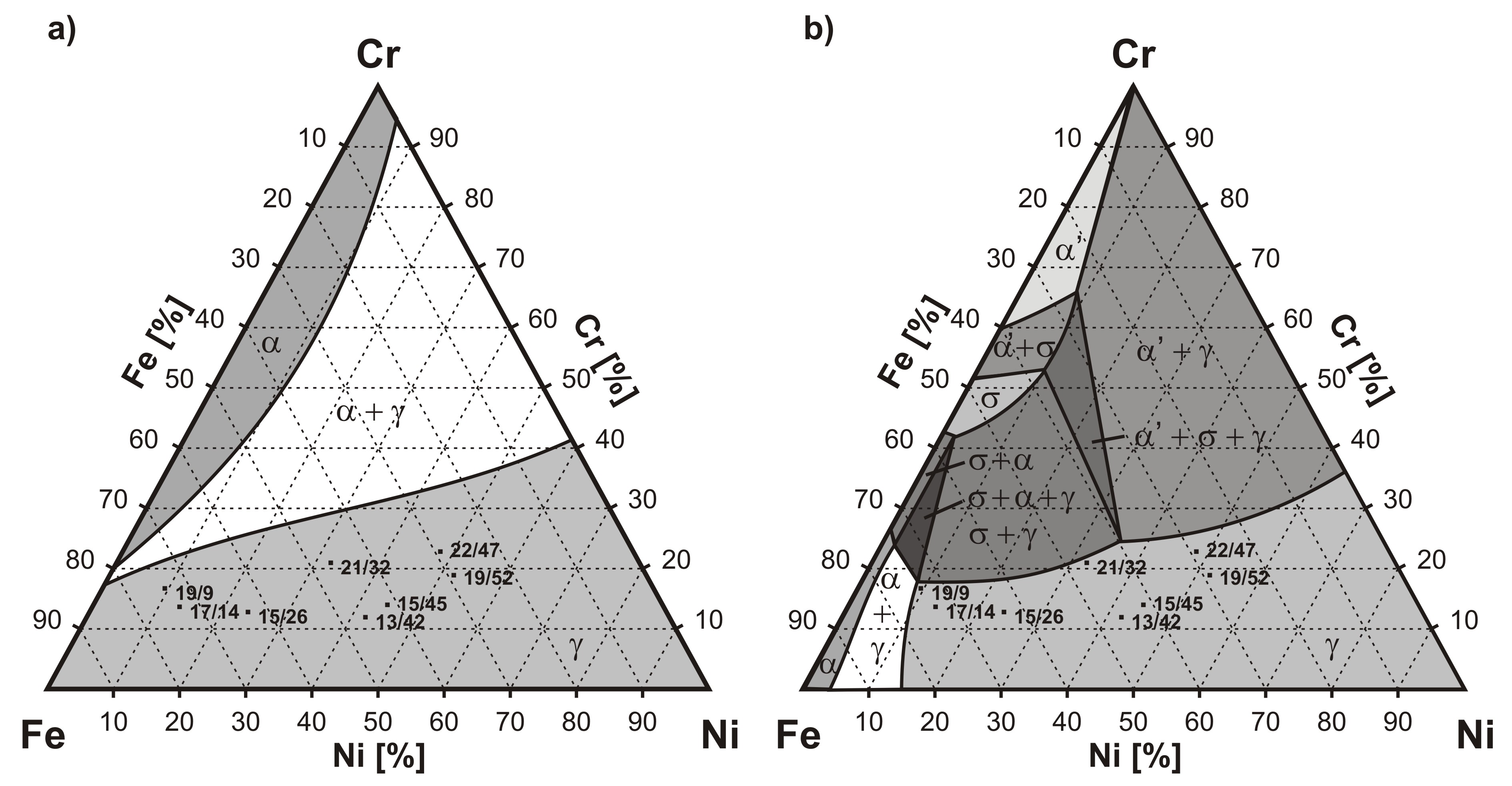
Fe ni phase diagram. (PDF) Magnetic phase diagram of the Fe-Ni system | Malin ... Comparison of the bcc magnetic phase diagram As shown in Figs. 1-4, none of the above descriptions As shown in Figs. 3 and 4, in the work of Swartzendruber for Fe-Ni alloys are in agreement with the experimental et al. [39], TC and b of bcc Ni are set to 0, which is obviously data [10-18,42-53] or the present ab initio calculations. unreasonable. PDF Towards a True Fe-ni Phase Diagram P phase equilibria are considered, few attempts have yet been made to incorporate FeNi ordering into the scheme of the existing Fe-Ni phase diagram. Notional diagrams involving FeNi ordering have been advanced [9,12], but many details remain to be resolved. Other Ordered Phases All Phase Diagrams - Polytechnique Montréal Al-Fe-Mn-O_Al2O3-FeO-MnO_1600C_P(O2)=1E-10_atm FToxid: Al-Fe-Na-O_Al2O3-Fe2O3-Na2O_P(O2)=air_1000C FToxid: Al-Fe-Na-O_Al2O3-FeO-Na2O_a(Fe)=1_1000C FToxid: Al-Fe-Ni_1273K FSstel: Al-Fe-Ni_1323K FSstel: Al-Fe-Ni_1523K FSstel: Al-Fe-O_Fe2O3-Al2O3-O2_air FToxid: Al-Fe-P_1173K FSstel: Al-Fe-S_FeS-Al2S3 FTOxCN: Al-Fe-S2_900C FTOxCN: Al-Fe … Phase diagrams for FE-CR-NI based alloys - Publications ... Part 1: Phase diagrams for binary and ternary alloys of FE, CR and NI with C and with SI. Publication metadata. Download and languages. Close. Available languages and formats.
Fe-Ni Binary Phase Diagram 50-90 at.% Ni - SpringerMaterials Section-Editor: Hiroaki Okamoto (Phase Diagrams) Cite this content Pierre Villars (Chief Editor), PAULING FILE in: Inorganic Solid Phases, SpringerMaterials (online database), Springer, Heidelberg (ed.) SpringerMaterials Fe-Ni Binary Phase Diagram 50-90 at.% Regulating the coordination structure of single-atom Fe ... Sep 19, 2019 · Energy diagram of benzene oxidation on Fe-N x C y SAs/N-C catalysts with the related reaction configurations on Fe-N 4 surrounded (IS: initial catalyst, MS1: the first H 2 O 2 cleavage adsorption ... FeNi Phase Diagram Animation - YouTube A rather basic attempt at animating the FeNi phase diagram - scientifically a little crude courtesy of my very amature animation skills Alloy steel - Wikipedia Alloy steel is steel that is alloyed with a variety of elements in total amounts between 1.0% and 50% by weight to improve its mechanical properties.Alloy steels are broken down into two groups: low alloy steels and high alloy steels. The difference between the two is disputed. Smith and Hashemi define the difference at 4.0%, while Degarmo, et al., define it at 8.0%.
Solid Solution of Metals: With Diagram | Metallurgy An ordered solid solution is a substitutional solid solution in which the atoms arrange themselves in a preferred manner, that is, the two species are arranged in some regular alternating pattern as illustrated in Fig. 2.3 (b), whereas Fig. 2.3 (a) illustrates a random solid solution in which the substitution of atoms has taken place at random. 金属 / Metal - Phase Diagram - Google Search 金属やセラミックスの状態図、エンリンガム図などの情報を提供しています。 一部、不確かなものもありますので、自己 ... › figure › Fe-Ni-phase-diagramFe-Ni phase diagram. [16] | Download Scientific Diagram [9,19] The alloy phases identified from XRD data agree with the information extracted from the Fe-Ni phase diagram (Figure 3). The higher atomic fraction of iron on sample A2, brings the... Fe-Ni - Phase Diagram Phase Diagram. このサイトを検索 ... Fe-Ni. Data from RICT-Sol alloy database ver.1.0. Sign in | Recent Site Activity | Report Abuse | Print Page | Powered By Google Sites ...
COPPER-ALUMINUM ALLOYS OF RARE EARTH METALS: PHASE EQUILIBRIA I
Fe-Ni-Al phase diagram in ALNI type permanent magnets ... Fe-Ni-Al phase diagram in ALNI type permanent magnets related area Abstract: With 36 alloys selected from indications provided first by differential thermal analysis and by other methods of analysis and physical measurements, it has been possible to specify accurately the Fe-Ni-Al ternary diagram. This research enabled us to : 1. Give a better ...
61. Local melting in Al embedded with TiNi powder induced by ...
Determination of the Fe-Ni phase diagram below 400°C ... The phase diagram for the Fe-Ni system below 400°C has been determined experimentally in the composition range from 0 to 52 wt pct Ni using analytical electron microscopy techniques. High spatial resolution X-ray microanalysis and electron diffraction were conducted on the Fe-Ni regions of meteorites. Both stable and metastable phase boundaries were defined.
metallurgy - Schaeffler, De Long, and WRC welding diagrams ...
File:Fe-Ni binary phase diagram.svg - Wikimedia Commons English: The binary phase diagram of Fe-Ni, focusing the area of temperature from 400 °C to 1600 °C and Ni mass percentage from 0 % to 50 %. Meanings of the symbols in the diagram are as follows: The diagram was drawn by the uploader based on the following reference: ステンレス協会(編). 1995.『ステンレス鋼便覧』第3版.
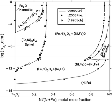
Fe-Ni-O (Iron-Nickel-Oxygen) | SpringerLink
PDF Phase stability in the Fe-Ni system: Investigation by first ... The accepted version of the Fe-Ni phase diagram contains a c-phase field extending from pure fcc-Fe to pure fcc-Ni, terminal solid solutions based on the bcc a and d phases of iron, and an intermetallic compound c0-Ni 3Fe with the L1 2structure [1,2]. In meteorite spec- imens, a c00-FeNi phase with the L1 0structure has also been found [3,4].

Experimental investigation of the effect of nickel on the ...
The Fe-Ni (iron-nickel) system | SpringerLink These changes are also applicable to this table as printed in "Fe-Ni (Iron-Nickel)" in Phase Diagrams of Binary NickelAlloys, P. Nash, Ed., ASM International (1991). The correct table is printed in this evaluation in Phase Diagrams of Binary lron Alloys, H. Okamoto, Ed., ASM International, to be published (1993). Cited References

Melting Curve and Phase Relations of Fe‐Ni Alloys ...
(PDF) Fe-Ni-Si (Iron-Nickel-Silicon) | Vijayaraghavan ... Part 1: Phase Diagrams for Binary Fig. 1. The previously known ternary phase of nominal and Ternary Alloys of Fe-Cr and Ni with C and with Si, Rep. formula Fe5Ni3Si2 (denoted s here) is present with a EUR 9657/I/EN, Comm. Eur. Communities, 1985, p 1-135 homogeneity range of 46.5-56.3 at.%
1. Introduction The ternary Fe-Ni-Ti alloys belong to the ...
The Fe-Ni-Al phase diagram in the Al-rich (>50 at.% Al ... The isothermal section of the Fe-Ni-Al phase diagram between 50 and 100 at.% Al at 850 °C was studied on 33 samples in sections at 60, 67, 71.5, 75 and 80 at.% Al, respectively. The results of XRD and EPMA analysis are summarized in the Table 1 and a graphical representation of phase equilibria is given in Fig. 1.
Application of dual-anneal diffusion multiples to the ...
File:Fe-Cr-Ni-solidus-phase-diagram.svg - Wikimedia Commons This file is licensed under the Creative Commons Attribution-Share Alike 3.0 Unported, 2.5 Generic, 2.0 Generic and 1.0 Generic license.: You are free: to share - to copy, distribute and transmit the work; to remix - to adapt the work; Under the following conditions: attribution - You must give appropriate credit, provide a link to the license, and indicate if changes were made.
Metals | Free Full-Text | Study on σ Phase in Fe–Al–Cr Alloys ...
Magnetic phase diagram of the Fe-Ni system - ScienceDirect The Fe-Ni phase diagram has been constructed by the CALPHAD (CALculation of PHAse Diagram) community [3], [4], [5], [6] and reviewed in the ASM handbooks [7], [8]. As far as the present authors know, these have been considered "standard" references in all subsequent studies and also adopted in numerous thermodynamic databases.

Some discussion topics on the representation of the ...
Melting Curve and Phase Relations of Fe-Ni Alloys ... @article{osti_1729736, title = {Melting Curve and Phase Relations of Fe-Ni Alloys: Implications for the Earth's Core Composition}, author = {Torchio, R. and Boccato, S. and Miozzi, F. and Rosa, A. D. and Ishimatsu, N. and Kantor, I. and Sévelin‐Radiguet, N. and Briggs, R. and Meneghini, C. and Irifune, T. and Morard, G.}, abstractNote = {We discuss that nickel is the second most abundant ...
Analysis of the Precipitation and Growth Processes of the ...
Fe-Ni Binary Phase Diagram 0-100 at.% Ni - SpringerMaterials Fe-Ni Binary Phase Diagram 0-100 at.% Ni Phase diagram available to subscribers If you are having trouble in accessing SpringerMaterials remotely during the COVID-19 pandemic, Get help with remote access To view content, please Log in, contact your Springer representative, or get a free trial General Information Apdic: non-APDIC

Quantitative elaboration of the defect structure of iron ...
PDF Fe-ni phase diagram - NASA Technical Reports Server (NTRS) Fe-ni phase diagram Alpha and gamma solubility limits in iron-nickel phase diagram at high temperatures - quench- and-anneal and diffusion couple techniques and electron probe microanalysis Document ID 19650020214 Document Type Technical Memorandum (TM) Authors Goldstein, J. I. (NASA Goddard Space Flight Center Greenbelt, MD, United States)
PHASE RELATIONS IN THE Fe–Ni–S SYSTEM FROM 875 TO 650 8C
Fe-Ni-P Phase Diagram at 6 GPa - NASA/ADS We have determined Fe-Ni-P phase diagram at 900°-1100°C and 6 GPa. At subsolidus conditions, the Metal-rich side of the ternary has three phases: Fe-Ni alloy, (Fe,Ni)3-xP, where x ≤ 0.6, and (Fe,Ni)2P. The melting begins at 950°C at the Ni-P join.

The Fe–Ni–Al phase diagram in the Al-rich (>50 at.% Al ...
› factsage › gedbFe-Ni Phase Diagram and Database (GeDb for FactSage) Fe-Ni Phase Diagram and Database (GeDb for FactSage) Fe-Ni Phase Diagram [2010Cac] The Fe-Ni system:Thermodynamic modeling assisted by atomistic caluculations, G.Cacciamani, A.Dinsdale, M.Palumbo, A.Pasturel, Intermetallics 18 (2010) 1148-1162. Database for FactSage ( registration required) [2011Xio] Magnetic phase diagram of the Fe-Ni system,
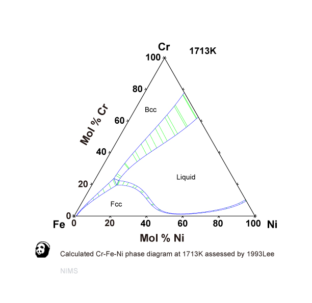
Cr-Fe-Ni NIMS)
The Fe-FeSi phase diagram at Mercury's core conditions ... At the conditions of Mercury's core, this quantity of nickel does not influence the melting temperature 51, and it leads to an expansion of fcc phase stability in the Fe-Ni-Si phase diagram ...

Диаграмма состояния системы Fe-Ni
Combinatorial Study of Phase Composition, Microstructure ... The phase map of the Co-Cr-Fe-Ni CCA sample. 2. Materials and Methods 2.1. Processing of the Combinatorial Film and Selection of the Studied Locations The combinatorial sample was manufactured by a novel PVD method known as multiple beam sputtering (manufacturer: Polygon Physics, Fontaine, France).
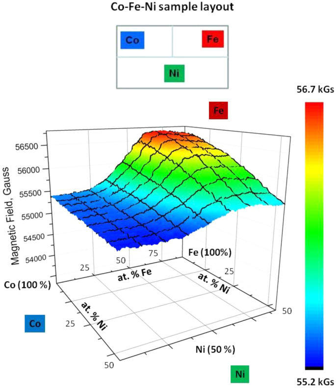
Magnetization–structure–composition phase diagram mapping in ...
TTT Diagram Basic - TTT diagram for steel, eutectoid steel Time-Temperature-Transformation (TTT) diagram or S-curve refers to only one steel of a particular composition at a time, which applies to all carbon steels.This diagram is also called as C-curve isothermal (decomposition of austenite) diagram and Bain’s curve.The effect of time-temperature on the microstructure changes of steel can be shown by the TTT diagram.

Electroplated Fe-Co-Ni films prepared from deep-eutectic ...
Compilative Fe - Ni phase diagram with author's correction ... The Fe - Ni phase diagram is no exception in this respect. Other examples of diagram of this type are the Mn - Ni and Ti - Cr ones; the difference in the temperatures of minimum on the liquidus and solidus lines and maximum in the range of layering of chemical compound is 110 °C in the Mn - Ni system and only 40 °C in the Ti - Cr system.
Solved (b) For Fe-Ni phase diagram determine the ratio of ...
Effects of Cr/Ni ratio on physical properties of Cr-Mn-Fe ... Physical properties of ten single-phase FCC Cr x Mn 20 Fe 20 Co 20 Ni 40-x high-entropy alloys (HEAs) were investigated for 0 ≤ x ≤ 26 at%. The lattice parameters of these alloys were nearly independent of composition while solidus temperatures increased linearly by ∼30 K as x increased from 0 to 26 at.%. For x ≥ 10 at.%, the alloys are not ferromagnetic between 100 and …
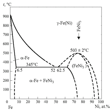
Compilative Fe – Ni phase diagram with author's correction ...
Precipitation Process in Fe-Ni-Al-based Alloys | IntechOpen 2. Phase diagrams of Fe-Ni-Al system. Figures 1 (a-d) show the calculated isothermal ternary phase diagrams of the Fe-Ni-Al system corresponding to 750, 850, 950 and 1100°C, respectively . In general, it can be seen that the liquid and ferrite phase regions decrease with the decrease in temperature.
arXiv:1410.0548v2 [cond-mat.mtrl-sci] 2 Feb 2015
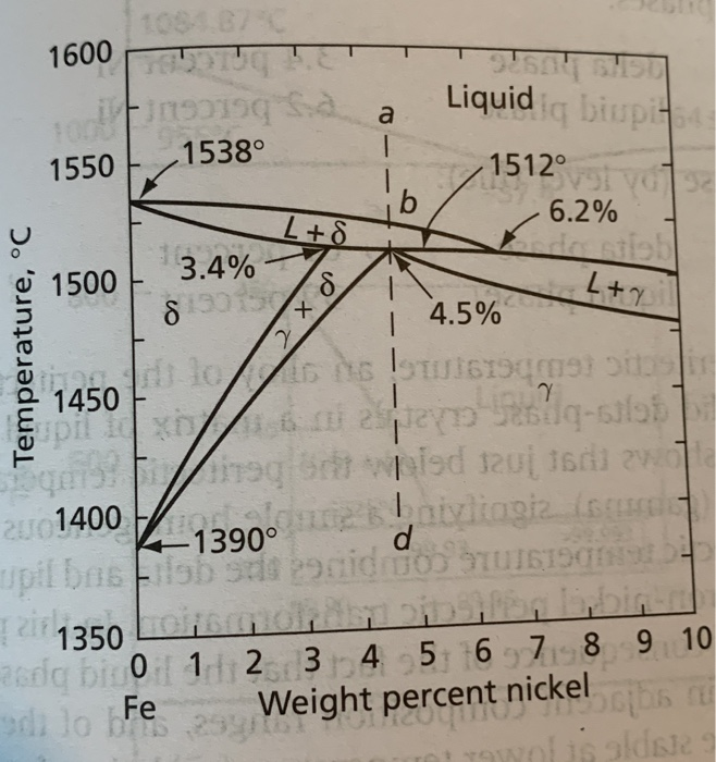
The Fe-Ni (iron-nickel) system by LJ Swartzendruber · 1991 · Cited by 337 — The present assessed Fe-Ni equilibrium diagram is shown in Fig. 1. Llquldus and Solidus. The liquidus and solidus for Fe-rich alloys up to about 12 at.% Ni were ...25 pages
.png)
Fe-Ni-C (1500 K) | Japan Atomic Energy Agency
› potentials › systemFe-Ni - NIST Oct 05, 2010 · The L12-Ni3Fe compound has the largest negative formation energy, which is consistent with the experimental Fe–Ni phase diagram. The L10–FeNi compound has also been observed experimentally in meteorite samples as a metastable phase. It is suggested here that the C11f compounds could also form in Fe–Ni alloys at low temperatures.
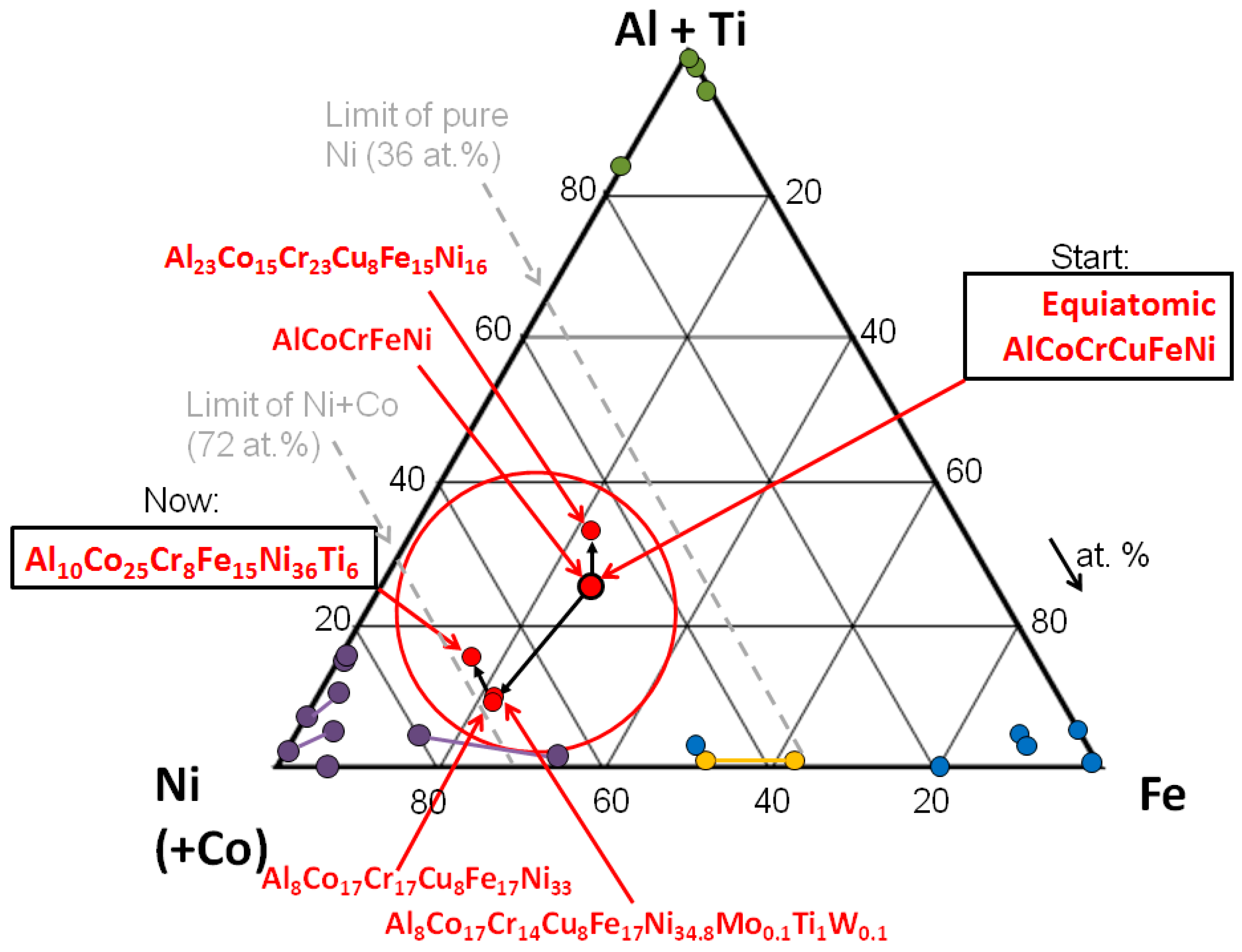
Entropy | Free Full-Text | On the Path to Optimizing the Al ...
Hollow carbon sphere encapsulated nickel nanoreactor for ... As green chemistry, aqueous-phase reactions play a vital role in modern fine chemical synthesis. Herein, an encapsulated nickel in a hollow carbon sphere ([email protected]) catalyst was constructed to effectively catalyze an aqueous-phase hydrogenation-rearrangement tandem (AP-HRT) reaction, in which water was employed as the solvent and reactant simultaneously.
Mat Sci 103 – Phase Transformations and Kinetics Spring ...
Fe-Ni Phase Diagram on Vimeo This can be directly understood from the Fe-Ni phase diagram: all metal is liquid above ca. 1500ºC. A solid solution crystallises below this temperature - gamma-Fe. This gamma-Fe decomposes below ca. 500-700ºC and depending on Ni-concentration into alpha-Fe (kamacite) and gamma-Fe (taenite).
![PDF] A REVISION OF PHASE RELATIONS IN THE SYSTEM Fe–Ni–S FROM ...](https://d3i71xaburhd42.cloudfront.net/61addb9d3961d083af891c209163d77a16e66cb6/5-Figure2-1.png)
PDF] A REVISION OF PHASE RELATIONS IN THE SYSTEM Fe–Ni–S FROM ...
Experimental and numerical modeling of the dissolution of ...
Collection of Phase Diagrams

Fe-Ni Phase Diagram and Database (GeDb for FactSage)

Melting Curve and Phase Relations of Fe‐Ni Alloys ...

File:Fe-Ni binary phase diagram.svg - Wikimedia Commons
Ternary phase diagram overview

Influence of Alloying Elements on Steel Microstructure ...

Catalytic nucleation of a meta-st... preview & related info ...

Thermodynamic phase predictions in High entropy alloys ...
Nickel in Steels – IspatGuru
PHASE DIAGRAMS AS TOOLS FOR ADVANCED MATERIALS DESIGN ...

C Fe Ni Phase Diagram | PDF

14 Ternary ideas | geology, ceramic arts daily, geology rocks
0 Response to "38 fe ni phase diagram"
Post a Comment