35 shear force and bending moment diagram for cantilever beam
PDF Shear force and bending moment of beams Beams Shear Force (SF) and Bending Moment (BM) diagrams. Solution: A Cantilever of length l carries a concentrated load W at its free end. Draw the Shear Force (SF) and Bending Moment (BM) diagrams. Consider the forces to the left of a section at a distance x from the free end. Then F = - W and is constant along the whole cantilever i.e. for all ... Shear Force and Bending moment Diagram for Cantilever Beam ... इस वीडियो के माध्यम से आप सीख सकते हैंCalculation For SFD and BMABasic knowledge also aad in middle videoMust listenAbout load.....
civilengineering.blog › 2017/09/11 › s-f-d-and-b-m-dBending moment and shear force diagram of a cantilever beam Sep 11, 2017 · Bending moment and shear force diagram of a cantilever beam By sanjay sharma 11 Sep 2017 13 Oct 2017 In this article Learn :cantilever beam Bending moment diagram B.M.D. and shear force diagram S.F.D. of a cantilever beam having point load at the end,several point loads,U.D.L.

Shear force and bending moment diagram for cantilever beam
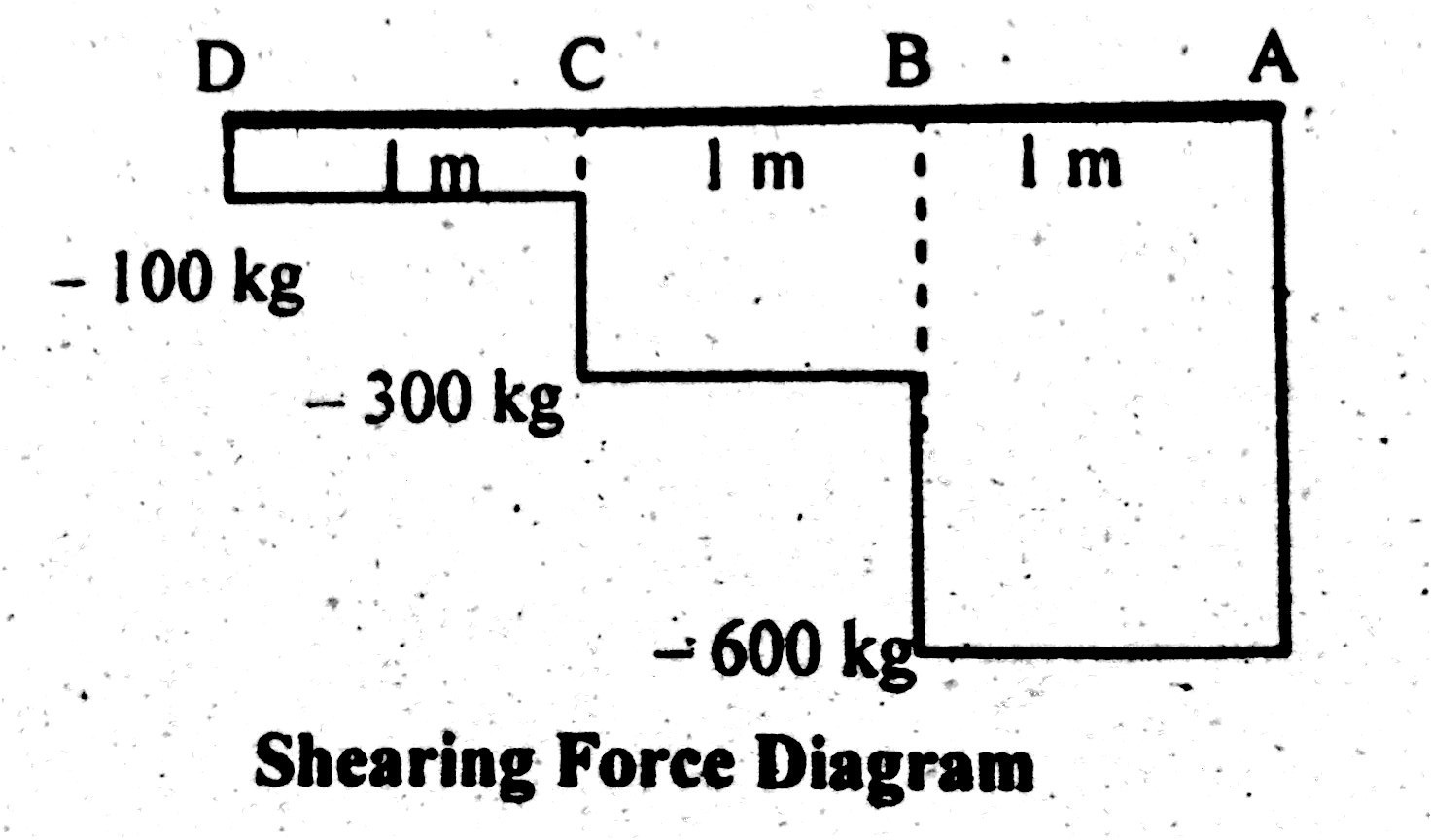
PDF Module -4 Shear Force and Bending Moment Diagrams can be visualized, namely, the bending moment and the shear force. It is also understood that the magnitude of bending moment and shear force varies at different cross sections over the beam. The diagram depicting variation of bending moment and shear force over the beam is called bending moment diagram [BMD] and shear force diagram [SFD]. draw the shear diagram for the cantilevered beam ... Drawing Shear Force Diagram In general application drawing shear force diagrams starts from left to right. Draw the shear and moment diagram for the beam. Shear force Between point D and C SF D-C -100 kg. This video explains how to draw shear force diagram and bending moment diagram with easy steps for a cantilever beam loaded with a ... web.ncyu.edu.tw › ~lanjc › lessonChapter 4 Shear and Moment In Beams - ncyu.edu.tw the beam. (1) Derive the shear force and bending moment equations. And (2) draw the shear force and bending moment diagrams. Neglect the weight of the beam. Solution Note that the triangular load has been replaced by is resultant, which is the force 0.5 (12) (360) = 2160 lb (area under the loading diagram) acting at the centroid of the loading ...
Shear force and bending moment diagram for cantilever beam. Shear Force & Bending Moment diagram for Cantilever Beam ... This video shows the shear force and bending moment diagram for a cantilever beam. Cantilever is the type of beam having fixed support at one end and free at... PDF Shear Force And Bending Moment Diagrams 'matlab beam shear force diagram and bending moment diagram may 3rd, 2018 - hi all my final year civil engineering assignment requires me to use matlab and create a shear force and bending moment diagrams for a simply supported beam t'' shear and moment diagrams for frames civil engineering Shear And Moment Diagram Cantilever Beam - The Best ... 4 5 Shear Force And Bending Moment Of Cantilever Beams Strength Materials. Sketch The Shear And Bending Moment Diagrams For Cantilever Beam Shown Given Following Parameters Omega A L Study. Solved Draw The Shear Force And Bending Moment Diagrams For Cantilever Beam Determine A Position Of Point Contraflexure Bend Course Hero. Free Online Beam Calculator for Cantilever or ... - SkyCiv Free online beam calculator for generating the reactions, calculating the deflection of a steel or wood beam, drawing the shear and moment diagrams for the beam. This is the free version of our full SkyCiv Beam Software. This can be accessed under any of our Paid Accounts, which also includes a full structural analysis software.
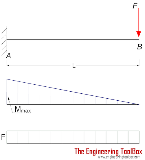
Draw Bending Moment & Shear Force Diagrams - Cantilever Beam This video explains how to draw shear force diagram and bending moment diagram with easy steps for a cantilever beam loaded with a concentrated load. Shear f... Shear Force Bending Moment - File Exchange - MATLAB Central 2.1.0.0. A bug concerning failure of the code to return the equations of bending moment and shear force from the beginning of the beam was fixed. Download. 26 Apr 2017. 2.0.0.0. This file has now been updated to deal with cantilever (a system with just one support). It can also handle cases of beams lying on the floor with the reaction being ... › articles › article5.7 Normal and Shear Stresses | Bending of Beams | InformIT Aug 01, 2019 · 5.7 Normal and Shear Stresses. When a beam is bent by transverse loads, usually both a bending moment M and a shear force V act on each cross section. The distribution of the normal stress associated with the bending moment is given by the flexure formula, Eq. Shear Force and Bending Moment Diagram for Cantilever Beam ... Generally, in the case of cantilevers, the shear force and the bending moment will be maximum at the supports. In this case the shear force is constant throughout the length of the cantilever. Maximum S.F = +W = +12kN Cantilever beam shear force diagram Maximum B.M = -WL = -12 x 4 = -48kN.m Result: Max S.F = +12kN (constant throughout the length)
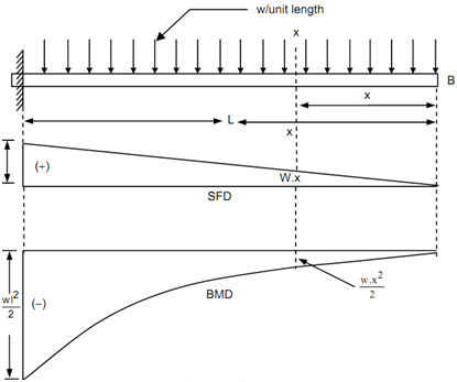
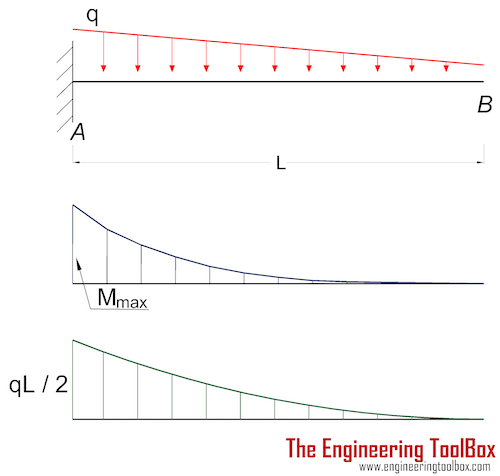
Cantilever beam Shear Force and Bending Moment diagram ... This video shows the shear force and bending moment diagram of a cantilever beam with triangular load. A cantilever beam is a type of beam with fixed support... Shear Force and bending moment diagram - ExtruDesign Shear force between any two vertical loads will be constant. And hence the shear force between the two vertical loads will be horizontal. The bending moment at the two ends of the simply supported beam and at the free end of a cantilever will be zero. Shear force and Bending moment Diagram for a Cantilever beam with a Point load at the free end Shear Force and Bending Moment diagram for cantilever beam ... In the other words, bending moment is the unbalancing moment of forces on any one side of the cross-section considered. Below diagrams are explain the shear force and bending moment diagram for Cantilever Beam. Concentrated load at the free end Uniformly distributed load Shear Force & Bending Moment Diagram of Cantilever Beam ... This shows shear force is maximum at fixed end and minimum at free end of cantilever beam. Shear Force Diagram Bending Moment Bending moment at point D = B.M (D) = 0 Bending moment at point C = B.M (C) = - (100×1) = -100 kg.m Bending moment at point B = B.M (B) = - (100×2 +200×1) B.M (B) = -400 kg.m
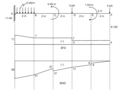
A cantilever beam is subjected to various loads as shown in ...
SHEAR FORCE and BENDING MOMENT DIAGRAM ( Cantilever Beam ... Thank you for watching. Doubts and comments are always welcome, please comment below if you have any doubt.Also don't forget to subscribe my channel. like an...
How to Draw Shear Force & Bending Moment Diagram | Simply ...
ecoursesonline.iasri.res.in › mod › pageDE-12: Lesson 19. SOLVED EXAMPLES BASED ON SHEAR FORCE AND ... 4. A simply supported beam is subjected to a combination of loads as shown in figure. Sketch the shear force and bending moment diagrams and find the position and magnitude of maximum bending moment. Solution: To draw the shear force diagram and bending moment diagram we need R A and R B. Fig. 19.4 Shear force and bending moment
Chapter 4: Internal Forces in Beams and Frames” in ...
How to draw the shear-force and bending-moment diagrams ... Answer: Start with the shear force diagram. Starting from the unsupported end of the cantilever you would start with zero shear force at the point where you first encounter applied load as you move today the fixed support. The shear force will increase linearly as you continue to move toward the ...
Solved Q1. Draw the shear force and bending moment diagrams ...
extrudesign.com › bending-moment-diagramShear Force and bending moment diagram for Simply supported Beam Sep 09, 2018 · The bending moment at the two ends of the simply supported beam and at the free end of a cantilever will be zero. Shear force and Bending moment Diagram for a Simply Supported beam with a Point load at the midpoint. Shear force and Bending moment Diagram for a Simply Supported Beam with a Uniformly distributed load
Shear Force and Bending Moment Diagrams Notes for Mechanical ...
Propped cantilever beam - Shear force & bending moment ... This video explains how to draw shear force & bending moment diagram in case of propped cantilever beam.Propped cantilever beam is a beam which is supported ...
Solved) - Draw the shear force and bending moment diagram of ...
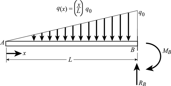
Solved: Draw the shear-force and bending-moment diagrams ... Draw the shear-force and bending-moment diagrams for a cantilever beam AB acted upon by two different load cases. (a) A distributed load with linear variation and maximum intensity q 0 (see figure part a) (b) A distributed load with parabolic variation and maximum intensity q 0 (see figure part b).

Draw the shear and bending moment diagrams for the beam shown ...
PDF Beam Design Formulas With Shear and Moment Introduction Notations Relative to "Shear and Moment Diagrams" E = modulus of elasticity, psi I = moment of inertia, in.4 L = span length of the bending member, ft. R = span length of the bending member, in. M = maximum bending moment, in.-lbs. P = total concentrated load, lbs. R = reaction load at bearing point, lbs. V = shear force, lbs.

structural engineering - Problem while solving for the moment ...
me.utep.edu › cmstewart › documentsLecture 2 - Shear and Bending Moment and Review of Stress 3.2 - Shear Force & Bending Moment Diagrams What if we sectioned the beam and exposed internal forces and moments. This exposes the internal Normal Force Shear Force Bending Moment ! What if we performed many section at ifferent values Of x, we will be able to plot the internal forces and bending moments, N(x), V(x), M(x) as a function Of position!
What is the shear force and bending moment of a cantilever ...
PDF CHAPTER 2 Shear Force And Bending Moment a) Calculate the shear force and bending moment for the beam subjected to a concentrated load as shown in the figure. Then, draw the shear force diagram (SFD) and bending moment diagram (BMD). b) If P = 20 kN and L = 6 m, draw the SFD and BMD for the beam. P kN L/2 L/2 A B EXAMPLE 4

Bending Moment Diagram - an overview | ScienceDirect Topics
PDF 4. Bending Moment and Shear Force Diagram The benefits of drawing a variation of shear force and bending moment in a beam as a function of 'x' measured from one end of the beam is that it becomes easier to determine the maximum absolute value of shear force and bending moment. The shear force and bending moment diagram gives a
Shear Force & Bending Moment Diagram of Cantilever Beam ...
Shear Force and Bending Moment Diagram for Cantilever Beam ... Today we will see here the concept to draw shear force and bending moment diagrams for a cantilever beam with a point load or force acting at free end with the help of this post.Let us consider one beam AB of length L as displayed in following figure.
Shear Force And Bending diagrams - Roy Mech
› what-is-shear-force-andWhat Is Shear Force and Bending Moment? - Civil Lead A bending moment diagram is a diagram which shows the bending moment at every section of the beam due to transverse loading on it. In the case of a simply supported beam bending moment is zero at the ends, and for a cantilever, it is zero at the free end.
Bending moment and Shear forces. 1 span 1 cantilever beam ...
[Solved] The Bending Moment Diagram of a cantilever beam ... ∴ Bending Moment at support (M s) = M. Take moment about the fixed end and equate it to zero. As there is no force, Fixed end moment = Applied moment. Important Points. In this case, bending moment is constant throughout the beam and shear force is zero throughout the beam. It is an example of pure bending.

How to draw shear Force & Bending moment diagram (Cantilever ...
Shear Force and Bending Moment Diagram for Simply ... As we know beam is simply supported at both ends and it will not resist the bending moment at the supports that is why, ∑M a = ∑M b= 0. From the shear force diagram, we can analyze that at point c, the shear force is minimum and at this point bending moment will be maximum.

4.5 Shear Force and Bending Moment of Cantilever Beams ...
Beam Calculator Online (Calculate the reactions, Draws ... Beam Calculator Online (Calculate the reactions, Draws Bending Moment, Shear Force, Axial Force) We updated the beam calculator interface and added additional features for calculating beams (calculation of statically indeterminate beams, image saving and section selection)! Clear beam. Save link on this calculation.
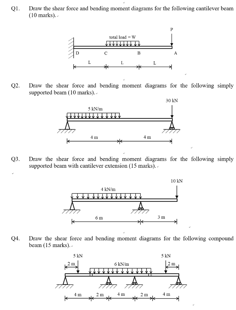
Solved Q1. Draw the shear force and bending moment diagrams ...
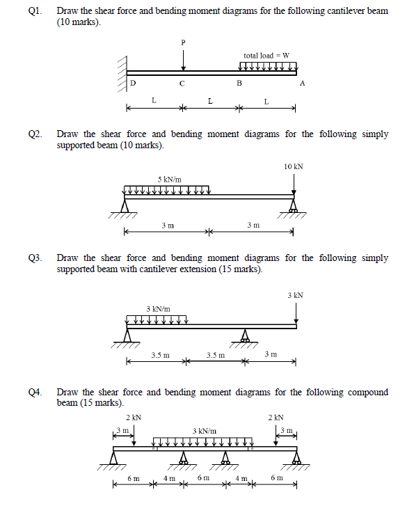
Q1. Draw the shear force and bending moment diagrams ... Draw the shear force and bending moment diagrams for the following cantilever beam. (Note: The bending moment is plotted in the tension side of the beam) (15 marks). 20 kN 15 kN/m 2 m 1 m Q2. Draw the shear force and bending moment diagrams for the following simply supported beam.
Solved: Draw the shear-force and bending-moment diagrams for ...
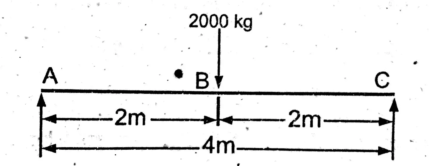
Shear Force and Bending Moment Diagram for Cantilever Beam Shear Force and Bending Moment Diagram of Cantilever beam when point load is applied From the figure we have the value of load at point A and point B. So let's draws the shear force diagram with the help of these loading. Bending moment at point A is zero. Bending moment at point B= -2*2 = 4 KN-M Bending moment at point C= -2*4-4*2 = 12 KN-M
Shear Force And Bending diagrams - Roy Mech
web.ncyu.edu.tw › ~lanjc › lessonChapter 4 Shear and Moment In Beams - ncyu.edu.tw the beam. (1) Derive the shear force and bending moment equations. And (2) draw the shear force and bending moment diagrams. Neglect the weight of the beam. Solution Note that the triangular load has been replaced by is resultant, which is the force 0.5 (12) (360) = 2160 lb (area under the loading diagram) acting at the centroid of the loading ...

Shear Force and Bending Moment Diagrams - Wikiversity
draw the shear diagram for the cantilevered beam ... Drawing Shear Force Diagram In general application drawing shear force diagrams starts from left to right. Draw the shear and moment diagram for the beam. Shear force Between point D and C SF D-C -100 kg. This video explains how to draw shear force diagram and bending moment diagram with easy steps for a cantilever beam loaded with a ...
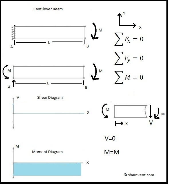
Shear and Moment Diagrams - S.B.A. Invent
PDF Module -4 Shear Force and Bending Moment Diagrams can be visualized, namely, the bending moment and the shear force. It is also understood that the magnitude of bending moment and shear force varies at different cross sections over the beam. The diagram depicting variation of bending moment and shear force over the beam is called bending moment diagram [BMD] and shear force diagram [SFD].
Cantilever beam - shear force diagrams, Mechanical Engineering

Shear Force and Bending Moment diagram for cantilever beam ...
Shear force and bending moment of beams
Module -4 Shear Force and Bending Moment Diagrams
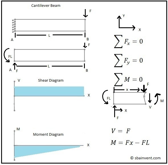
Shear and Moment Diagrams - S.B.A. Invent
Solved] Question5 please :D | Course Hero

Everything You Should Know About Cantilever Beams - The ...

Drawing Shear Force, Bending Moment Diagram » File Exchange ...
Cantilever Beams - Moments and Deflections
Cantilever Along A Uniformly Distributed Load, Shear Force ...
![[Ex. 07] Shear Moment Diagram Cantilever Beam Distributed Load Part I](https://i.ytimg.com/vi/qMk5IVKcZQM/maxresdefault.jpg)
[Ex. 07] Shear Moment Diagram Cantilever Beam Distributed Load Part I

All About Structural Analysis and Design - Cantilever Beam ...

Draw shear force and bending moment diagram for cantilever ...
Cantilever Beams - Moments and Deflections
![Cantilever Beam: Shear Force and Bending Moment Diagram [SFD BMD Problem 2] By Shubham Kola | Facebook](https://lookaside.fbsbx.com/lookaside/crawler/media/?media_id=257535155732524&get_thumbnail=1)
Cantilever Beam: Shear Force and Bending Moment Diagram [SFD BMD Problem 2] By Shubham Kola | Facebook
0 Response to "35 shear force and bending moment diagram for cantilever beam"
Post a Comment