39 pressure balancing loop diagram
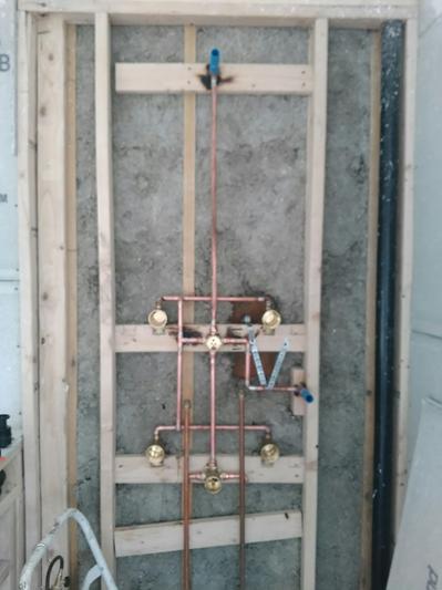
PDF Circuit Balancing Valves - Armstrong Fluid Technology building. Using the mechanical engineer's design drawings, the balancing contractor carefully adjusts each balancing valve throughout the HVAC system to ensure the engineer's design intent is met, and that the correct flow rate is achieved in each circuit. Performance curves correlate the pressure drop (ΔP) of the Pressure balancing loop for body spray | Terry Love ... I see how that would work but I've plumbed in a loop without the H configuration and I'm curious if I have to redo it. I would order the diagram you posted but these sprays are the R50200 I've mounted sideways. With the threaded conections I HAVE to loop it around to a tee then to the diverter. If the pressure is good I'm thinking I should be okay.
PDF STEAM BALANCING - invenoinc.com simple balance flow diagram. The steam balance flow diagram can be accomplished in many different ways, such as a fully devolved document completed in Aspen software to a simple flow diagram completed with Microsoft Visio. The key point is to have a steam balance document for plant personnel. END RESULTS OF A STEAM BALANCE Implementing a ...

Pressure balancing loop diagram
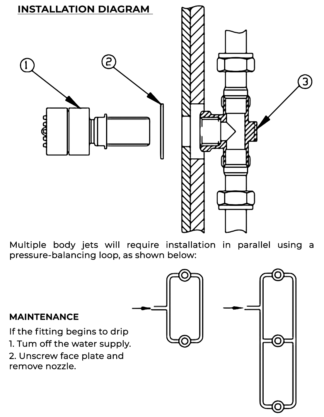
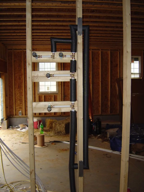
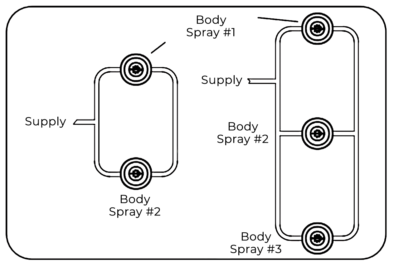
Plumbing | Body Sprays - CSide Decorating When 2 or more body sprays are used, they need to be installed in a pressure balancing loop so that all of the sprays have equal flow, pressure and temperature. Typically, three sprays are used and installed in a vertical line. Ideal body spray placement is intended to cover the entire body with water no matter which way the person is facing. Pressure Difference Dynamic Balancing Valve - Hotowell HTW-71-DV Series Dynamic Balancing Valve.pdf >> General . HTW-71-DV Series electric dynamic pressure balance valve is a dynamic equilibrium with the electric control integration products, mainly for air-conditioning equipment, HVAC system at the end (such as air box, new air handling units, air handlers) temperature control, intelligent modules configured to control devices on the loop can ... Causal Loop Diagrams « System Dynamics Causal Loop Diagram A diagram that shows causal links among actions, information, and consequences. Sometimes referred to as the influence diagram or directed graph. Causal Loop Diagram is a useful way to represent interrelationships and system structure of the parts that make up the system. They show the relevant parts of a system using textual…
Pressure balancing loop diagram. Glycol Loop - ProBrewer Discussion Board With no restriction at that point in the loop, you will get little or no flow through your coils. Also add a T and pressure gauge immediately upstream of the bypass reg so you can set the regulator to where you want it--usually 2/3 to 3/4 the rated safe pressure for your coils or jackets. PDF PG03 Guidelines for Drawing Causal Loop Diagrams "Production Pressure"is inserted in between them. 10.A shortcut to determining whethera loop is balancing or reinforcing is to count the number of "o's" in the loop. An odd numberof "o's" indicates a balancing loop (i.e., an odd numberof U-turns keeps you headed in the opposite direction); an even num- Causal Loop Diagrams - transentis We differentiate between two kinds of feedback loops: balancing (or negative) feedback loops and reinforcing (or positive) feedback loops. The diagram above shows that if schedule pressure is high, then productivity is increased, which also increases the completion rate. This reduces the number of open tasks, which reduces the schedule pressure Compressed Air Basics - Piping - Air Compressor Works, Inc. Compressed Air Basics - Piping. February 23, 2018. Your air compressor is the heart of your air system. Most customers focus on the compressor and consider the piping as a secondary concern. However, just like a heart can fail because of clogged arteries, a compressor can fail because of improper piping. You have many different options on the ...
PDF Introduction to Systems Thinking and Causal Loop Diagrams Loop Diagrams BAE 815 (Fall 2017) Dr. Zifei Liu ... Balancing loops can be automatic, or intentional policy. 14 Combination loops Births Dynamic behavior Deer population + R + Available food + B - ... Pressure for long-term fix-+ R Time Efforts quick fix Problem symptom Capacity of system Complete Guide to Shower System with Body ... - FaucetList.com A pressure balancing loop ensures that all of the body sprays have equal flow, pressure, and temperature. A Few More Quick Shower System Layout Design Tips If you plan on using an overhead rain showerhead or ceiling mounted shower head in your walk-in shower with jets, make sure that the drain is not positioned directly below the showerhead. PDF Cooling Tower Pumping and Piping - Xylem Applied Water "closed" loop is that due to flow-friction pressure drop; static heights are not considered. Figure 1 Static Height (H) Not Considered for Pump Selection in Closed Loop The "open" or tower circuit is different from the "closed" loop circuit. The difference is that all static heads are not cancellable. What is Causal Loop Diagram? (With Examples) Edit this Diagram. Cause Loop Diagram Example - Growth and Investment. A Growth and Underinvestment structure is simply an elaborated Limits to Growth structure where the growth inhibitor is part of another Balancing Loop with an external standard and some delay.
Body spray pressure balance loop - DoItYourself.com ... Plumbing and Piping - Body spray pressure balance loop - I'm plumbing 3 body-sprays in my shower. I'm making a pressure balancing loop. Due to piping req'ts, I am unable to position the loop inlet exactly in the middle of the non-fixture side. Is this okay, or do I need to make sure that the pipe distances from the What is a Pressure Balance Valve? (with pictures) John Sunshine Date: February 28, 2022 A pressure balance valve prevents water from being scalding in the shower.. A pressure balance valve is a sophisticated plumbing device that reacts to changes in the pressure of the delivery water. Typically, both hot and cold water sources are fed into the valve, and its job is to ensure that the volume of water that leaves it is a constant mix of these ... PDF How to Draw Causal Loop Diagrams - ESCAP Diagrams Can Have Multiple Loops Learning by doing Loop The more the NGO achieved results in its work, the better its reputation. People Loop The better its reputation, the higher quality people it was able to hire, boosting its capacity. Money Loop Also, the better its reputation, the more funds were available, boosting capacity. Pressure and Flow Control Loop Interaction | Control Notes Once the pressure controller was tuned, we put it in automatic control mode and redid the step tests on the flow loop, to include the effect of the pressure controller running/interacting in automatic control. We tuned the flow loop for a slow and damped response using the Lambda tuning rules. When both control loops were properly tuned, we ...
Vertical Spa Systems | Trusted E Blogs | Shower plumbing, Tub ...
PDF HYDRONIC BALANCING - Caleffi Caleffi North America, Inc. 9850 South 54th Street Franklin, WI 53132 T: 414.421.1000 F: 414.421.2878 Dear Hydronic Professional, Welcome to the 2nd edition of idronics - Caleffi's semi-annual design journal for hydronic professionals.

Why a Balancing Loop Can Help a System Correct Itself ...
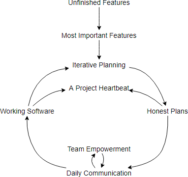
Causal Loop Diagram - systemsthinkinglab.com Causal loop diagrams map the causal relationships between pairs of elements within a system and identify feedback loops. These loops can either be reinforcing (vicious cycle) or balancing (goal-seeking) and complex interactions between loops can lead to unintended consequences. The arrows in the diagram describe the directions of effect.
Causal Loop Diagrams: Little Known Analytical Tool
Domestic Hot Water Recirculation Part 7: Balancing Systems ... This is because it helps balance out the pressure drop between the various circuits. Manual balancing may require some touch. Whenever possible, JMP always recommends automatic flow balancing devices. However, when manual balancing must be used, many people use a hands-on balancing method.This means physically touching each riser pipe at start ...
Pressure loop for two sets of body sprays | Terry Love ...
Systems Mapping: How Paris meets Climate Change - Medium B4, B5, B6 show the loops influencing political pressure. As balancing loops keep the system stable, these loops tend to absorb policy efforts and could hinder a wider change.
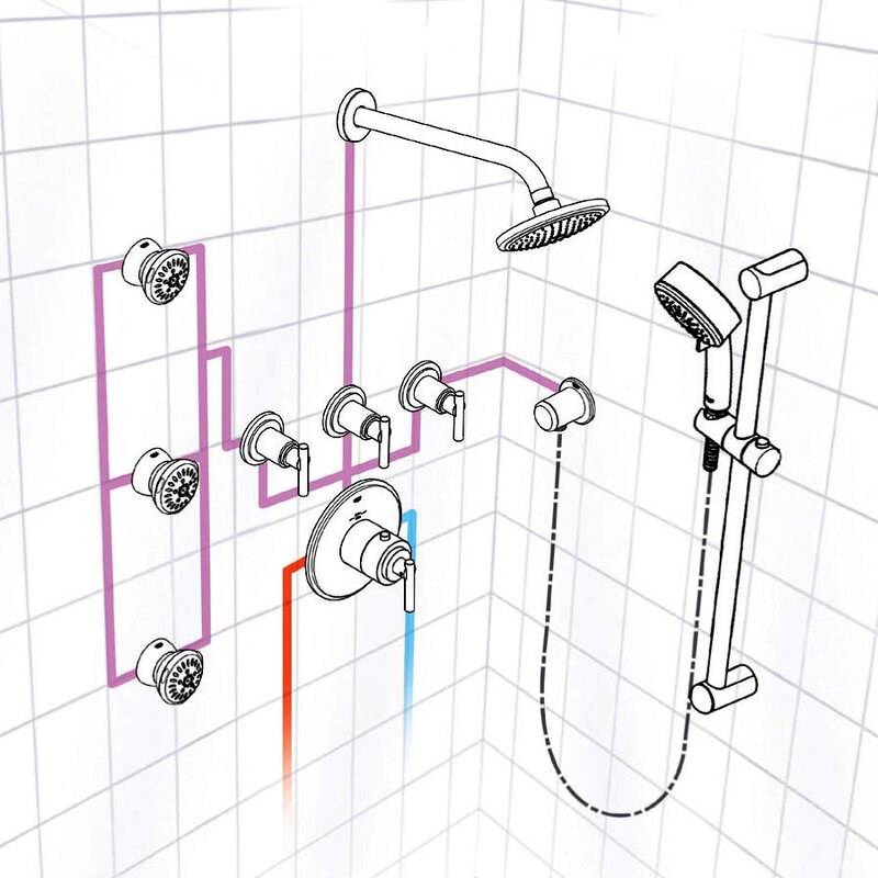
6 Jetted Body Massage Shower System with Rain Shower Head ...
PDF Shower Design Guide - Moen A pressure-balancing loop must always be used with body sprays to allow for equal supply of water to each spray. Maximum of 3 on 1 outlet. 2 body sprays may be operated as one function. Shower can be operated and personalized remotely with the U by Moen app, which is available for Android and iOS. Showerhead, Arm and Flange Handshower, Drop Ell ...

Causal Loop Diagram - Tool/Concept/Definition
PDF Back to Basics: Pumping Systems - rockymtnashrae.com Closed loop heating and cooling piping ... Extreme head differences will create balancing and control difficulties 4 . ... Pressure is maintained by impeller speed, so if pressure at pump needs to stay constant regardless of flow, may not be much advantage to VSP.
Pressure Balancing Loops | Plumbing Zone - Professional ...
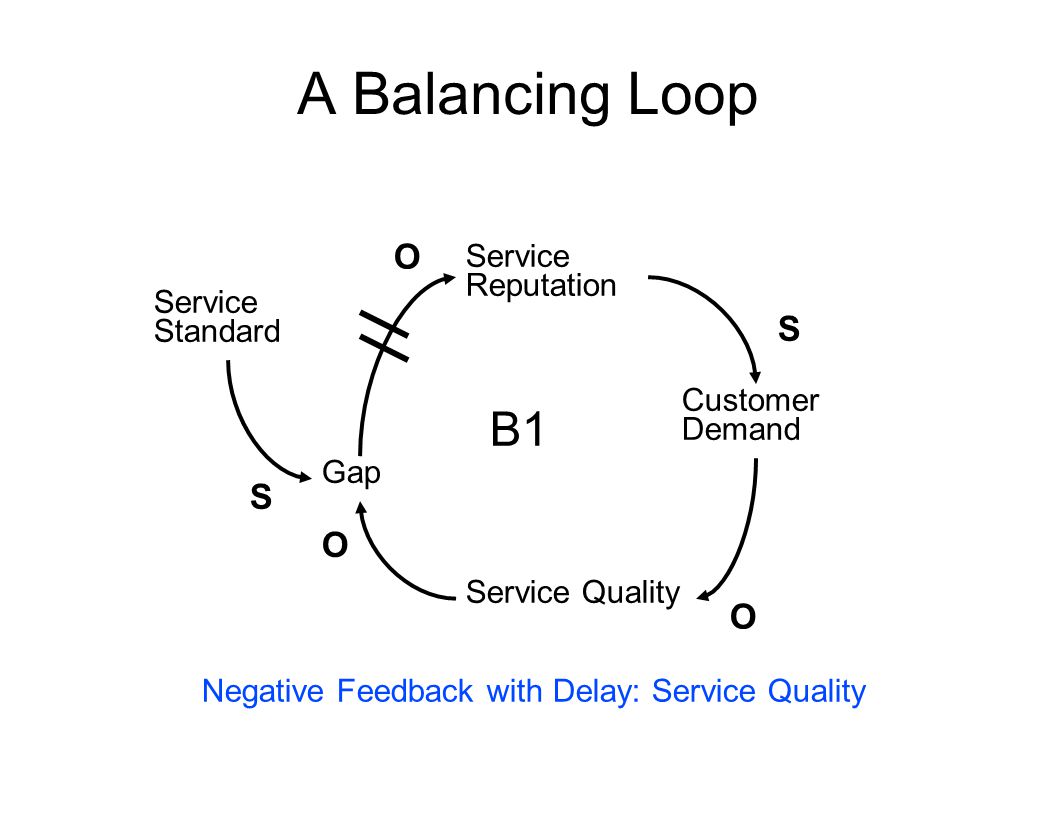
Balancing Loop Basics - The Systems Thinker In causal loop diagrams, balancing loops are noted by a "B," a "—," or a scale icon in the center of a loop. The Structure of Balancing Loops. There is always an inherent goal in a balancing process, whether it is visible or not. The basic structure of a balancing loop involves a gap between the goal (or desired level) and the actual ...
HydraChoice® Body Spray Rough R50200 | Delta Faucet
PDF Drawing Causal Loop Diagrams 6. Name the loop: Give your loop a name! 7. Test and share your loops: Read the diagram as if you were telling a story. "As average com-muting times goes up, pressure to widen roads or add lanes goes up. As this pressure increas-es, the amount of new highway construction goes up. With more roads/lanes added, average commute time goes down.
Causal loop diagram of dispensing errors
Pressure Balancing Loops | Plumbing Zone - Professional ... Pressure Balancing Loops. Jump to Latest Follow 1 - 7 of 7 Posts. D. DDial · Registered. Joined Dec 4, 2017 · 11 Posts . Discussion Starter · #1 · Jan 26, 2018. Seeing if anyone out there can give me some clear validation towards these 2 methods of piping. ...

Understanding Primary Secondary Pumping Part 1: Behold the ...
PDF Guidelines for Drawing Causal Loop Diagrams course of action included in the diagram. For example, an increase in "Production Pressure" may increase "Production Output," but it may also increase "Stress" and decrease "Quality" 5. All balancing loops are goal-seeking processes. Try to make explicit the goals driving the loop.

Love me some Reddit plumbing roasts… fire away : r/Plumbing
Causal Loop Diagram - Tool/Concept/Definition A causal loop diagram (CLD) explains the behavior of a system by showing a collection of connected nodes and the feedback loops created by the connections. One or more of the nodes represent the symptoms of the problem. The rest of the nodes are the causal chains causing the problem.. The simplest possible CLD contains two nodes. Below is an example from video 3 in The Dueling Loops Video Series.
FONTANA VERSILIA COLOR CHANGING LED best rain showerhead
Causal Loop Diagrams « System Dynamics Causal Loop Diagram A diagram that shows causal links among actions, information, and consequences. Sometimes referred to as the influence diagram or directed graph. Causal Loop Diagram is a useful way to represent interrelationships and system structure of the parts that make up the system. They show the relevant parts of a system using textual…
P&IDs AND LOOP DIAGRAMS
Pressure Difference Dynamic Balancing Valve - Hotowell HTW-71-DV Series Dynamic Balancing Valve.pdf >> General . HTW-71-DV Series electric dynamic pressure balance valve is a dynamic equilibrium with the electric control integration products, mainly for air-conditioning equipment, HVAC system at the end (such as air box, new air handling units, air handlers) temperature control, intelligent modules configured to control devices on the loop can ...
System Behavior and Causal Loop Diagrams
Plumbing | Body Sprays - CSide Decorating When 2 or more body sprays are used, they need to be installed in a pressure balancing loop so that all of the sprays have equal flow, pressure and temperature. Typically, three sprays are used and installed in a vertical line. Ideal body spray placement is intended to cover the entire body with water no matter which way the person is facing.
Body Spray Loop System
How to Draw Causal Loop Diagrams

Structure of Pressure balance loop. | Download Scientific Diagram

Causal loop diagram - Wikipedia

Learn to Read Causal Loop Diagrams – Systems & Us

A causal loop diagram showing behavioral loops. A balancing ...
Can anyone propose an alternative pressure balancing loop ...
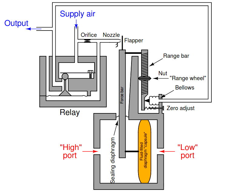
Pneumatic Moment-balance Differential Pressure Transmitter

Installation Instructions For Fontana Lima Ultra Waterfall ...
FONTANA VERSILIA COLOR CHANGING LED best rain showerhead
What is Causal Loop Diagram? (With Examples)

Pressure Balancing Loops | Plumbing Zone - Professional ...

Four Quarters Mechanical Inc. - Princeton University Image ...
![PDF] The Karma of Products : Exploring the Causality of ...](https://d3i71xaburhd42.cloudfront.net/bc0730766ec18390f9768fb170f98fac21ba421d/37-Figure6-1.png)
PDF] The Karma of Products : Exploring the Causality of ...
Trick to plumbing multiple shower heads? | DIY Home ...

Figure 3. Causal loop diagram depicting the role of education ...

Structure of Pressure balance loop. | Download Scientific Diagram

Neo-Proterozoic Model Overview
Teaching Cause and Effect: Systems Thinking - ppt video ...

Causal Loop Diagram

Causal Loop Diagram - Tool/Concept/Definition

Balancing Loop

Structure of pressure balance loop. | Download Scientific Diagram
The Systems Thinker – Fine-Tuning Your Causal Loop Diagrams ...

Causal loop diagram - Wikipedia
0 Response to "39 pressure balancing loop diagram"
Post a Comment