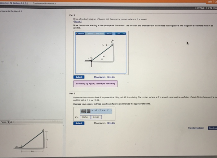
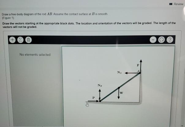
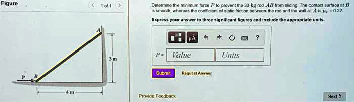
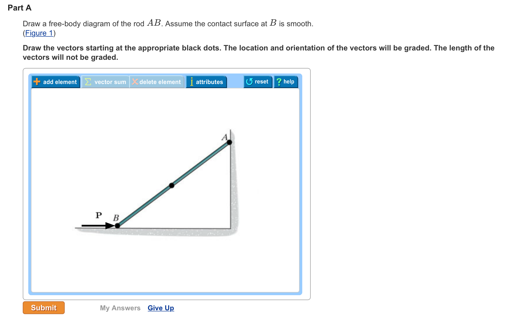
36 draw a free-body diagram of the rod ab. assume the contact surface at b is smooth.
What is a Free-Body Diagram and How to Draw it (with ... Examples of drawing free-body diagrams. To better understand how to draw free-body diagrams using the 3 steps, let's go through several examples. Example 1. A box is pushed up an incline with friction which makes an angle of 20 ° with the horizontal. Let's draw the free-body diagram of the box. The first step is to sketch what is happening: PDF ME 230 Kinematics and Dynamics - University of Washington rod = 10 kg. The pendulum has an angular velocity of 3 rad/s when = 45 and the external moment of 50 N m. Find: The reaction at the pin O when = 45 . Plan: Draw the free body diagram and kinetic diagram of the rod and sphere as one unit. Then apply the equations of motion. W. Wang 18
PDF 5 Solutions 44918 - WordPress.com Draw the free-body diagram of the "spanner wrench" subjected to the 20-lb force. The support at A can be considered a pin, and the surface of contact at B is smooth. Explain the significance of each force on the diagram. (See Fig. 5-7b.) A B 6 in. 20 lb 1 in. *5-8. Draw the free-body diagram of member ABC which
Draw a free-body diagram of the rod ab. assume the contact surface at b is smooth.
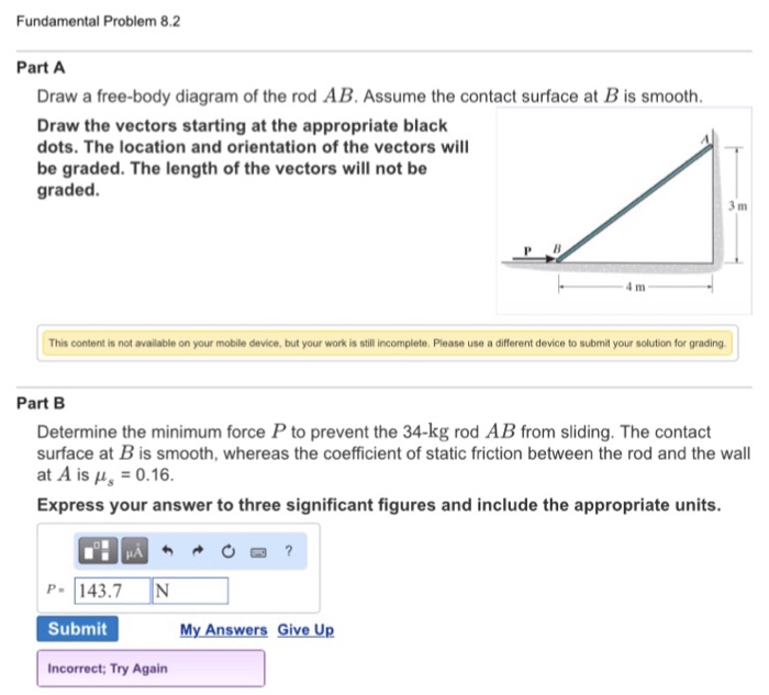
PDF ENGR-1100 Introduction to Engineering Analysis FREE-BODY DIAGRAMS (Section 5.2) 2. Show all the external forces and couple moments. These typically include: a) applied loads, b) support reactions, and, c) the weight of the body. Idealized model Free-body diagram (FBD) 1. Draw an outlined shape. Imagine the body to be isolated or cut "free" from its constraints and draw its outlined shape. PDF Islamic University of Gaza 5—6. the free-body diagram af the crane boom AB which has a weight of 650 1b and center of gravity at G. The boom is supported by a pin at A and cable BC. The load of 1250 1b is suspended from a cable attached at B. Explain Lhc significance of each force acting on the diagram. (See Dr. Ahmed A. Abu-foul T.A: Eng. Waseem (Younis 30 sithBo COS So › homework-help › questions-andSolved A) Draw a free-body diagram of the rod AB. Assume ... A) Draw a free-body diagram of the rod AB. Assume the contact surface at B is smooth. B)Determine the minimum force P to prevent the 34-kg rod AB from sliding. The contact surface at B is smooth, whereas the coefficient of static friction between the rod and the wall at A is μs = 0.25. Question: A) Draw a free-body diagram of the rod AB ...
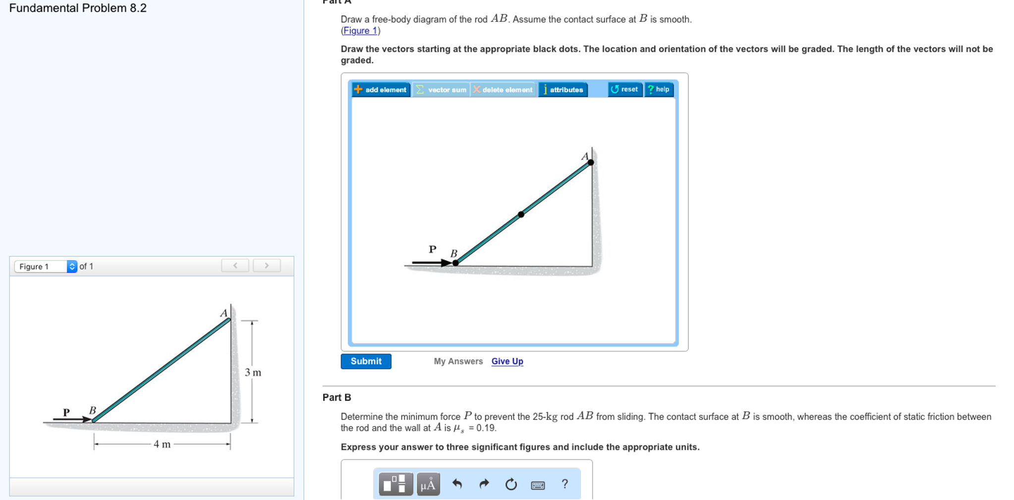
Draw a free-body diagram of the rod ab. assume the contact surface at b is smooth.. Problem 309 | Equilibrium of Concurrent Force System ... Problem 309 A cylinder weighing 400 lb is held against a smooth incline by means of the weightless rod AB in Fig. P-309. Determine the forces P and N exerted on the cylinder by the rod and the incline. › homework-help › questions-andSolved Fundamental Problem 8.2 3 of 4 > Draw a free-body ... Fundamental Problem 8.2 3 of 4 > Draw a free-body diagram of the rod AB Assume the contact surface at B is smooth 3 m P B 4 m Draw the vectors starting at the appropriate black dots. The location and orientation of the vectors will be graded. The length of the vectors will not be graded. PDF UTEP To construct a free-body diagram for a rigid body or any group bodies considered as a single system, the following steps should be performed: Draw Outlined Shape. Imagine the body to be isolated or cut "free" from its COnstraints and connections and draw (sketch) its outlined shape. Show All Forces and Couple Moments. 5.7 Drawing Free-Body Diagrams | University Physics Volume 1 Figure 5.32 (a) The free-body diagram for isolated object A. (b) The free-body diagram for isolated object B. Comparing the two drawings, we see that friction acts in the opposite direction in the two figures. Because object A experiences a force that tends to pull it to the right, friction must act to the left. Because object B experiences a component of its weight that pulls it to the left ...
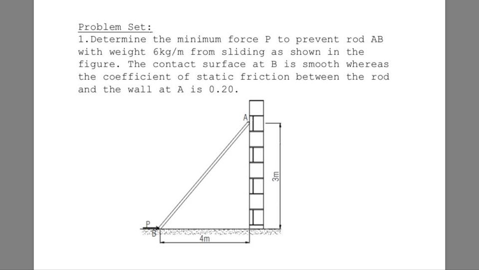
(Solved) - Determine the minimum force P to ... - Transtutors The contact surface at B is smooth, whereas the coefficient of static friction between the rod and the wall at A is Us=0.2. The rod is diognal on the wall from bottom left (B), with the force P applied at B towards the right, to top right (A). It is 4 m across and 3 m up. Making the rod 5 m long. 5.7 Drawing Free-Body Diagrams - OpenStax Figure 5.32 (a) The free-body diagram for isolated object A. (b) The free-body diagram for isolated object B. Comparing the two drawings, we see that friction acts in the opposite direction in the two figures. Because object A experiences a force that tends to pull it to the right, friction must act to the left. Because object B experiences a component of its weight that pulls it to the left ... PracticeProblemsForFinalExam - EM 306 Statics Finals ... A rod of length 3 R and weight W is placed in a hemispherical bowl of radius R. It will slide until it comes to rest at an angle Neglect friction and assume that the bowl does not rock (it is fixed on the floor). a. Draw a free-body-diagram for the rod and show the reactions at the two places where the rod contacts the bowl. Tension, String, Forces Problems with Solutions Problem 1. A block of mass 5 Kg is suspended by a string to a ceiling and is at rest. Find the force Fc exerted by the ceiling on the string. Assume the mass of the string to be negligible. Solution. a) The free body diagram below shows the weight W and the tension T 1 acting on the block. Tension T 2 acting on the ceiling and F c the reaction ...
› homework-help › questions-andSolved Draw a free-body diagram of the rod AB. Assume the ... Draw a free-body diagram of the rod AB. Assume the contact surface at B is smooth. Draw the vectors starting at the appropriate black dots. The location and orientation of the vectors will be graded. The length of the vectors will not be graded. Determine the minimum force P to prevent the 28-kg rod AB from sliding. › homework-help › questions-andSolved Part A Draw a free-body diagram of the rod AB. Assume ... Mechanical Engineering. Mechanical Engineering questions and answers. Part A Draw a free-body diagram of the rod AB. Assume the contact surface at B is smooth. Draw the vectors starting at the appropriate black dots. The location and orientation of the vectors will be graded. The length of the vectors will not be graded. › homework-help › questions-andSolved Draw a free-body diagram of the rod AB. Assume the ... Draw a free-body diagram of the rod AB. Assume the contact surface at B is smooth. Draw the vectors starting at the appropriate black dots. The location and orientation of the vectors will be graded. The length of the vectors will not be graded. Determine the minimum force P to prevent the 34-kg rod AB from sliding. study.com › academy › answerDraw a free-body diagram of the rod AB. Assume the contact ... Answer to: Draw a free-body diagram of the rod AB. Assume the contact surface at B is smooth. Determine the minimum force P to prevent the 28-kg...1 answer · Top answer: Given: • Mass of the rod AB is m=28 kgm=28 kg • The coefficient of static friction between the rod AB and the ground is μ=0μ=0 • The...
Answered: 1. Determine the minimum force P to… | bartleby
PDF Free Body Diagram Exercises - Engineering Example: Free Body Diagrams The roller-band device consists of two rollers, each of radius, r, encircled by a flexible band of negligible thickness and subjected to the two tensions T. Draw the FBD to allow the contact force, R, between the band and the flat supporting surfaces at A and B to be determined. The action is in the horizontal plane
SECOND MIDTERM -- REVIEW PROBLEMS
TORQUE - Translational and Rotational Equilibrium Problems and the tension in the rope is 5000 N, a) Draw the free body diagram b) Determine the weight of the object. (VERY Important Note – We can treat ...12 pages

Determinethe force in the cable
Draw a free-body diagram of the rod ab. Assume ... - Brainly.com Nov 22, 2019 — Click here to get an answer to your question ✍️ Draw a free-body diagram of the rod ab. Assume the contact surface at b is smooth.1 answer · 0 votes: Answer:See attachment Explanation:
Solved Draw a free-body diagram of the rod AB. Assume the ...
5.7 Drawing Free-Body Diagrams - University Physics Volume 1 Figure 5.32 (a) The free-body diagram for isolated object A. (b) The free-body diagram for isolated object B. Comparing the two drawings, we see that friction acts in the opposite direction in the two figures. Because object A experiences a force that tends to pull it to the right, friction must act to the left. Because object B experiences a component of its weight that pulls it to the left ...
Solved 3 m P B. 4 m A Review Draw a free-body diagram of ...
Problem 326 | Equilibrium of Force System - MATHalino Problem 326 The cylinders in Fig. P-326 have the indicated weights and dimensions. Assuming smooth contact surfaces, determine the reactions at A, B, C, and D on the cylinders.

Laws Of Motion - Problem solving tips
Free Body Diagram Questions and Answers - Study.com Draw a free body diagram of the ball. View Answer. Earth satellite moves in a circular orbit with an orbital speed of 6200 m/s. (a) Draw a free body diagram for the satellite. (b) Find the time ...
Chapter 4 – Homework Problems
Hibbeler chapter5 - SlideShare Given: M = 20 gm a = 75 mm b = 200 mm θ = 40 deg Solution: A x , A y , NB force of glass on rod. M(g) N force of gravity on rod. Problem 5-7 Draw the free-body diagram of the "spanner wrench" subjected to the force F. The support at A can be considered a pin, and the surface of contact at B is smooth.
Hibbeler chapter5
(Solved) - Determine the minimum force P to ... - Transtutors Draw a free-body diagram of the rod AB. Assume the contact surface at B is smooth. Draw the vectors starting at the appropriate black dots. The location and orientation of the vectors will be graded.

Lecture #7 Part a 2D Rigid Body Equilibrium - ppt video ...
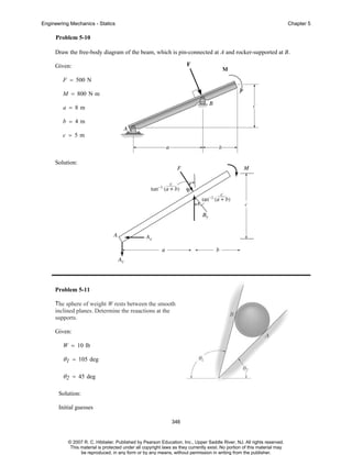
PDF Chap. 5 Equilibrium of a Rigid Body - 國立臺灣大學 p.216, 5-9. Draw the free-body diagram of the beam, which is pin- ... smooth surface and an equal portion of the load is supported at both the front and rear tires. 5-32. ... components of reaction at the pin C and the force developed in rod AB on the crane when x = 5 m. 5-34. 5-35 p.235, 5-60. The uniform rod has a length l and weight W. It is ...
Solved] Determine the n- and t-components of the force F ...
How to Draw a Free Body Diagram: 10 Steps (with Pictures) To draw a free body diagram, start by sketching a simple representation of the body you want to make the diagram of, like a square to represent a box. Next, draw arrows on the shape that show the forces acting on the object. For example, draw a downward arrow to signify the weight of the object, since gravity pulls the object down.
Chap. 2 Force Vectors
(PDF) Solutionmanual 5a | Fatih Demir - Academia.edu Draw the free-body diagram of the bar, which has a 75 3mm in. negligible thickness and smooth points of contact at A, B, 30 and C. Explain the significance of each force on the 5 in.mm 125 diagram. (See Fig. 5-7b.)
5 Solutions 44918
Drawing Free-Body Diagrams - Physics Classroom Drawing Free-Body Diagrams. Free-body diagrams are diagrams used to show the relative magnitude and direction of all forces acting upon an object in a given situation. A free-body diagram is a special example of the vector diagrams that were discussed in an earlier unit. These diagrams will be used throughout our study of physics.

Determine the minimum force P to prevent the 30-kg rod AB from sliding
Mechanics of Solids S.S. Bhavikatti Pages 51-100 - FlipHTML5 Table 2.2 Free Body Diagrams (FBD) for a Few Typical CasesReacting Bodies FBD required for FBD B a ll W RSm ooth T Smooth Ball R W 600 N 600 N R1 WP Sm ooth Ladder G P R2 T 400 N Block weighing 600 N600 N 600 N R2.13 EQUILIBRIUM OF BODIESA body is said to be in equilibrium when it is at rest or has uniform motion.
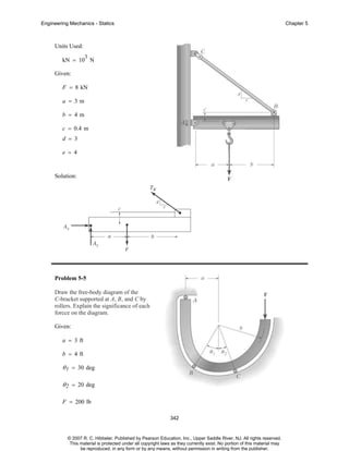
STATICS
5.7 Drawing Free-Body Diagrams - General Physics Using ... Figure 5.32 (a) The free-body diagram for isolated object A. (b) The free-body diagram for isolated object B. Comparing the two drawings, we see that friction acts in the opposite direction in the two figures. Because object A experiences a force that tends to pull it to the right, friction must act to the left. Because object B experiences a component of its weight that pulls it to the left ...
SOLVED:Figure Detolinina Mtnintln Torci lo Mutuni Ino je (ot ...
› homework-help › questions-andSolved A) Draw a free-body diagram of the rod AB. Assume ... A) Draw a free-body diagram of the rod AB. Assume the contact surface at B is smooth. B)Determine the minimum force P to prevent the 34-kg rod AB from sliding. The contact surface at B is smooth, whereas the coefficient of static friction between the rod and the wall at A is μs = 0.25. Question: A) Draw a free-body diagram of the rod AB ...

PDF) Statics 13-5 solutions | 소현 문 - Academia.edu
PDF Islamic University of Gaza 5—6. the free-body diagram af the crane boom AB which has a weight of 650 1b and center of gravity at G. The boom is supported by a pin at A and cable BC. The load of 1250 1b is suspended from a cable attached at B. Explain Lhc significance of each force acting on the diagram. (See Dr. Ahmed A. Abu-foul T.A: Eng. Waseem (Younis 30 sithBo COS So
12.2 Examples of Static Equilibrium | University Physics Volume 1
PDF ENGR-1100 Introduction to Engineering Analysis FREE-BODY DIAGRAMS (Section 5.2) 2. Show all the external forces and couple moments. These typically include: a) applied loads, b) support reactions, and, c) the weight of the body. Idealized model Free-body diagram (FBD) 1. Draw an outlined shape. Imagine the body to be isolated or cut "free" from its constraints and draw its outlined shape.
Solved Draw a free-body diagram of the rod AB. Assume the ...

Ch 12 Static Equilibrium & Elasticity
Draw a free-body diagram of the rod AB. Assume the | Chegg.com
16.2 Constrained Plane Motion: EGN3321-21Summer CM01
Chap. 2 Force Vectors
5 Solutions 44918
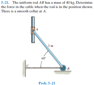
Answered: –21. The uniform rod AB has a mass of… | bartleby
Solved Part A Draw a free-body diagram of the rod AB. Assume ...
Engineering Mechanics 1st Year
Statics 13-5 solutions

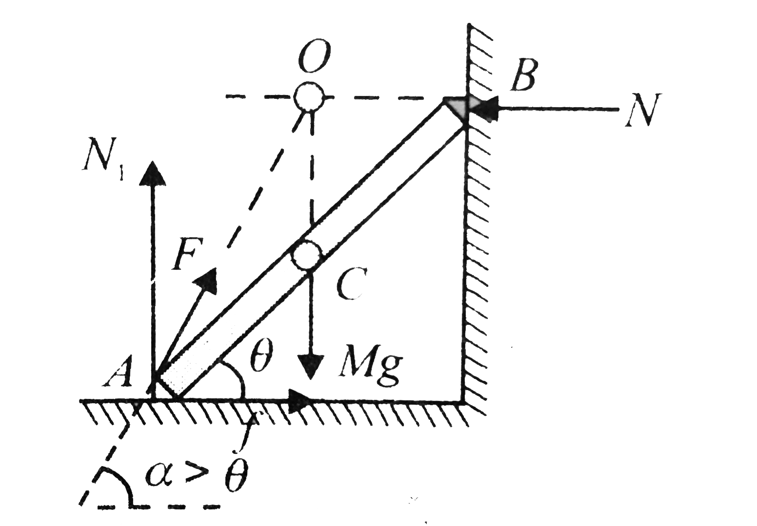
A rod AB of weight w(1) is placed over a sphere of weight w(2) shown in figure.Ground is rought and there is no friction between rod and sphere and sphere and wall. Draw free body diagrame of sphere ...
Lectures notes On Engineering Mechanics
Page 1 of 6 [3 Hours] [Marks 80] NB: 1. Question No: 1 is ...
12.2 Examples of Static Equilibrium – University Physics Volume 1
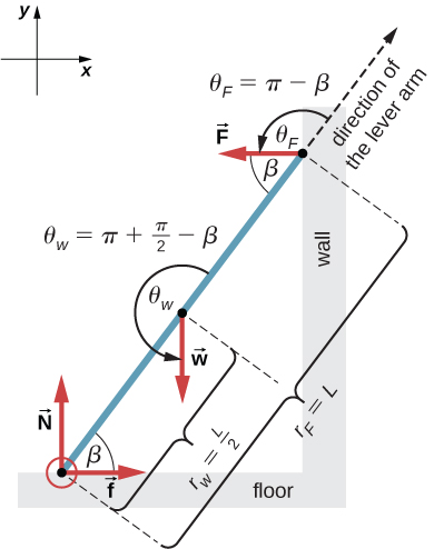
A rod AB rests with the end A on rough horizontal ground and ...
Hibbeler chapter5
Untitled

Untitled

PDF) Chapter 5 Equilibrium of a rigid body | alvick lau ...
0 Response to "36 draw a free-body diagram of the rod ab. assume the contact surface at b is smooth."
Post a Comment