39 lng process flow diagram
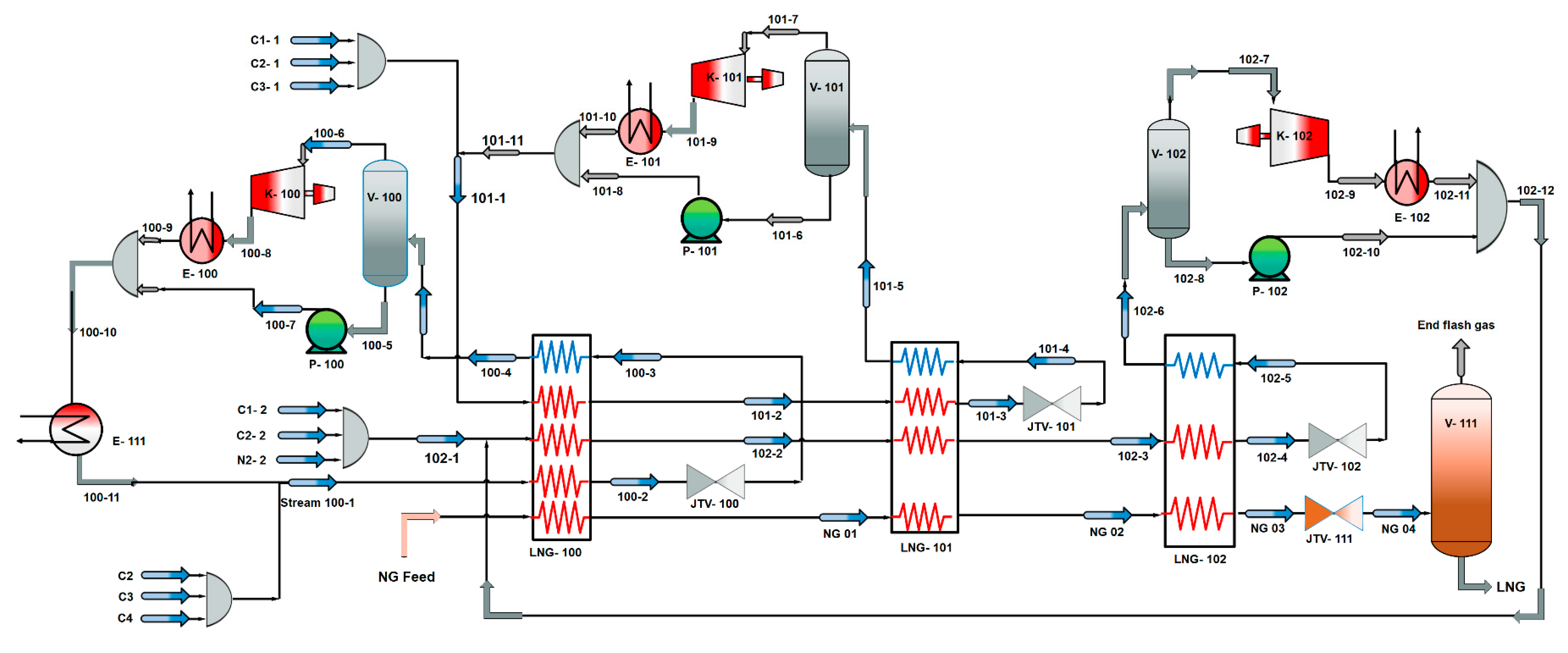
–Onshore LNG vs. FLNG, baseload plants vs. tolling facilities •Market views / growth of LNG –Industry statistics, project forecasts, and LNG news •Review of liquefaction projects and process technologies –History, size, and growth of LNG trains and complexes –Licensor share, process selection, cycle efficiency, equipment, etc. Liquefied Natural Gas or LNG is natural gas with the primary element as methane. ... 5 shows a Schematic of a Simple Refrigeration Cycle (LNG Process Flow) ...
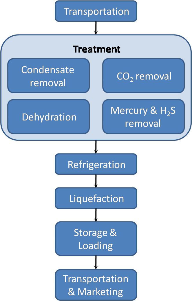
The LCI was initiated with the drawing of a flow diagram specifically for Western Australian LNG production in Darwin and Karratha (Figure 1) in which the boundaries for each of the above mentioned...
Lng process flow diagram
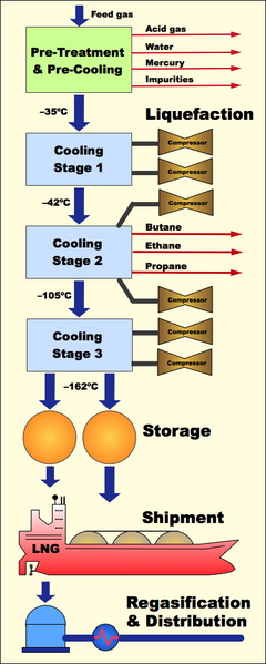
Process Flowchart This is a diagram that analyzes and illustrates the overall flow of steps involved in the production of a service or product. Finalizing procedures You can use the chart to create your final SOPs. These provide details about the tools and methods used in a process. •At atmospheric pressure LNG has a temperature of about –162ºC •LNG contains about 85-95 % methane •LNG is colorless, odorless, non-corrosive and non-toxic •Evaporated LNG can displace oxygen and cause human suffocation •Flammability range, 5-15 vol % concentration in air •Autoignition temperature, 540 C 5 LNG is a cryogenic liquid Liquefied Natural Gas (LNG): Natural gas from which impurities like sulphur and carbon-dioxide Diagram about LNG Ships Membrane Tank Structure: Unlike independent tanks, membrane tanks This method of gassing up is called "Piston Flow Method". In this the lighter specific gravity LNG...
Lng process flow diagram. Natural gas is liquefied at -160˚C and 1 atm and this will reduce its volume by 600 times. Figure 2.2 shows a typical block flow diagram of an LNG train. Plant condensate Field condensate. LPG C5+ Condensates. Figure 2.2 A typical LNG train block flow diagram. 2.3.2 GTL Process. Feb 02, 2022 · Developing and/or checking overall plant and unit simulations using standard process simulation programs (Hysys, Pro II, Unisim, and/or Promax), including development of H&MBs. Developing and/or checking Process Flow Diagram (PFDs) and Utility Flow Diagrams (UFDs) being able to explain selected flow configuration. Process flow diagrams and flowcharts are words used correspondingly and refer to making a diagram that documents a business process. The only difference between these two is that process flow mapping refers to the actual process of creating a diagram; the diagram itself is called a flowchart. Lng Process Flow Diagram - Hanenhuusholli Sep 26, 2019A typical lng import terminal process flow diagram is shown in figure 5. What is lng. At LNG terminals, the liquified natural gas is turned back into gaseous state (regasified) after unloading from ships and then distributed across the network.
Natural Gas Liquefaction. TEP 10 - Gas Processing and LNG - Fall 2008. Jostein Pettersen. Simplified LNG plant block diagram. Compressed air and inert gas Landfafallcilities. Offshore utility substation. MEG process MEG substationarea MEG storage tank. Liquefied Natural Gas Process - an overview. 8 hours ago The following is a general guideline for the startup for an LNG production plant. Processes and pump services in the lng industry. 5 hours ago Liquefaction Process A block flow diagram of the liquefaction process is shown in... Figure 18: Process Flow Diagram of C3‐MR. LNG. Inlet Gas. The split is due to the process flow diagram and the complex nature of the cold box setup described in earlier sections. A mixed refrigerant of mainly of propane and nitrogen is employed in this process. LNG plant normal operation . Molecular sieve unit: Designed to meet the product specifications on water and mercaptans (RSH) content. The main items that should be checked in this unit: • Mercaptans buildup • Regeneration gas temperature • Flow rate • Flow channeling • Oxygen • Inlet separator • Bed fouling • Dehydratation bed ...
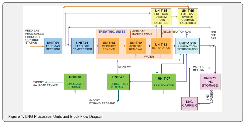
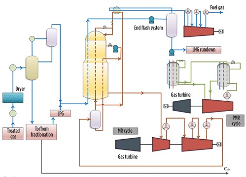
scale plants (processing natural gas directly from the field and exporting the LNG to high-value markets in large "parcels") with those of small- to mid-scale plants (processing of pretreated feed gas from a pipeline). Hence the market demands more flexible and cost-effective construction models for... The image below is a schematic flow diagram of a typical oil refinery depicting various unit processes and the flow of intermediate products between the inlet crude oil feedstock and the final products. The diagram depicts only one of the hundreds of different configurations. It does not include any of the usual facilities providing utilities such as steam, cooling water, and … Different types of natural gas liquefaction plants have been developed globally to meet rising demand for LNG. LNG gaining ground as gas demand soars. Energy plays a prominent role in the quality of human life A typical MFC process flow diagram is shown in Fig. 5. Precooling is carried out in a... The LNG Plant will receive gas from the LNG Project Gas Pipeline, treat it and then liquefy it using refrigerants. It may produce refrigerant make-up and will produce condensate in a fractionation system. Figure 4.3 is the simplified process flow diagram for the plant.
YAMAL LNG: MEETING THE CHALLENGES OF NATURAL GAS LIQUEFACTION ...
Flow Meter Types Used in Midstream Oil and Gas October 25, 2018- For as long as there Startup & Commissioning Packages in the Cove Point LNG Plant December 18, 2017- IFS recently completed Process-Flow-Diagram-PID-Nitrogen-Generation-Membrane-Package. March 7, 2017 Welcome.

Liquified Natural Gas: Properties, Uses, Origin, Composition ...
Nov 05, 2021 · Gametogenesis occurs when a haploid cell (n) is formed from a diploid cell (2n) through meiosis. We call gametogenesis in the male spermatogenesis and it produces spermatozoa.. In the female, we call it oogenesis. It results in the formation of ova. This article covers both oogenesis and spermatogenesis.
LNG R&D for the Liquefaction and Regasification Processes
storage tanks, which takes approximately 14-16 hours. The LNG remains at -160°C for the duration of the process. LNG has been transported commercially by ships since 1964 and as of the end of 2016 there have been 88,000 cargoes or 176,000 voyages without an LNG loss. T. ransPorTaTion. A 155,000 m. 3. membrane vessel is approximately the same ...

Natural Gas Liquefaction - ScienceDirect
A process flow diagram illustrates the equipment and the flow of chemicals included in the process. The PFD only shows major equipment such as pumps, vessels, columns, heaters, turbines, etc. at an industrial plant. However, it does not show minor details or components like designations, flow...
LNG Plants – Technical operations (Part II)
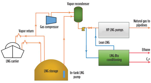
Figure 1 - LNG Receiving Terminal Simplified Process Flow Diagram. The LNG receiving terminal receives liquefied natural gas from special ships, stores the liquid in special storage tanks, vaporises the LNG, and then delivers the natural gas into a distribution pipeline.
Liquefied natural gas - Wikipedia
A simplified process flow diagram of the ConocoPhillips Optimized Cascade® Process is shown in Figure 1. In this liquefaction process, multiple Several LNG projects are feed gas flow constrained. This situation occurs both on new projects being considered and also at existing LNG facilities.

LNG industry faces challenge of monetizing huge CSG resources ...
1.3 LNG Bunkering process and guideline structure . LNG bunkering is the process of transferring LNG fuel to a ship from a bunkering facility. The sequence for a bunkering operation carried out between two parties for the first time is described in the following diagram; the references identify the applicable sections of the guideline.

6 Block Flow Diagram of an LNG plant. | Download Scientific ...
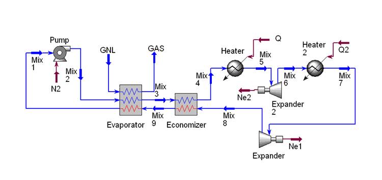
Additionally, the feed gas was mostly LNG in the previous studies. However, in the liquefaction process for ships, the BOG is the target of cooling, which has a 2.3. Process Flow Diagram. As previously described, the key points of the marine liquefaction process are compactness and simplicity.
Basic Properties of LNG
The liquefied natural gas (LNG) industry continues to grow worldwide, and there are many LNG terminals planned for the US in response to growing natural Figure 3 shows a simplified process flow diagram for acid gas removal. The amine solvent pumps are often the largest pumps in the plant...

Coming out of the Ice Age | LNG Industry
Flow Meter requirements vary, from mass flow to volume flow and beyond. That’s why we’ve broken down each flow meter type for you, so you can decide which type of meter is the best for your unique application. From Coriolis flow meters, to magnetic flow meters, we offer a comprehensive, industry-leading portfolio of flow measurement devices.

Seamless integration of subsea architecture with Floating LNG ...
(a) Process flow diagram of partial re-liquefaction system; (b) Process flow diagram of cascade partial re-liquefaction system . Kim et al. (2019) [ 37 ] studied the different JT re-liquefaction processes with pressurized BOG as the refrigerant, while adding a liquid turbine to the re-liquefaction configuration with 2946.5 kg/h BOG.

Gas Gorgon gas project Liquefied natural gas Regasification ...
Liquefied Natural Gas (LNG) is Natural Gas that has been cooled to –260° F (–162° C), changing it from a gas into a liquid that is 1/600th of its original vo...
Troubleshooting Identification and Upset Conditions Effect of ...
The following is a general guideline for the startup for an LNG production plant. A generic C3MCR liquefaction train process flow diagram is shown in Figure 7-2.Startup of other liquefaction technologies may be slightly different.
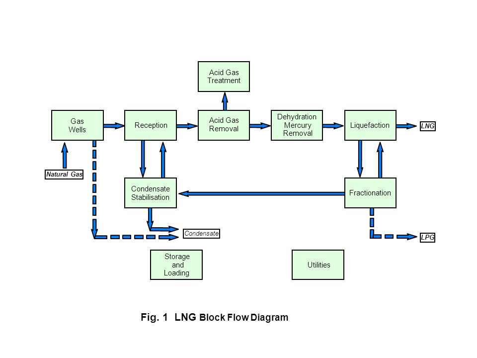
Fig. 1 LNG Block Flow Diagram
A process flow diagram (PFD) is a diagram commonly used in chemical and process engineering to indicate the general flow of plant processes and equipment. The PFD displays the relationship between major equipment of a plant facility and does not show minor details such as piping details...
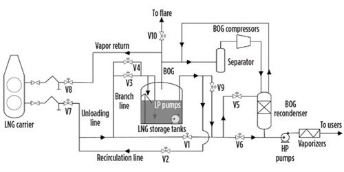
Optimization of BOG management during LNG unloading with ...
Included are drying, treating, dehydrogenation, effluent cleanup, hydrogen, liquefied natural gas, syngas, sulfur, liquid treating, etc. Each process description includes a flow diagram as well as application, economics and licensor information. The processes are indexed by process and contributing company. 2019 Gas Processes Handbook
Energies | Free Full-Text | Shuffled Complex Evolution-Based ...
How to Read Process Flow Diagrams that used in Oil&Gas and power plant. What is Process Flow Diagram?Process Flow Diagram (PFD) is a simple drawing that...

Condition monitoring of LNG plants - Brüel & Kjær Vibro
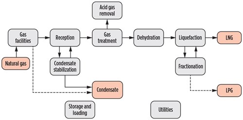
Natural Gas Industry Process Flow Diagram Create Process Flow Diagram examples like this template called Natural Gas Industry Process Flow Diagram that you can easily edit and customize in minutes. 1/16 EXAMPLES EDIT THIS EXAMPLE Text in this Example: Natural Gas Industry Gas Distribution Gas Processing Plant Gas Production Oil Well Gas Well
Onshore LNG Production Process Selection
A Process Flow Diagram (PFD) is a diagram which shows the relationships between the main components in a system. Process Flow Diagrams are widely used by engineers in chemical and process engineering, they allows to indicate the general flow of plant process streams and...
Liquefied Natural Gas (LNG)
Process Flow Diagram (PFD) is a drawing which essentially captures the process flow for a processing plant. PFD is used to capture the This type of diagram has its roots in the 1920s. In 1921, industrial engineer and efficiency expert Frank Gilbreth, Sr. introduced the "flow process chart"...
Liquefied natural gas: technology choices and emissions
Differential Pressure Flow Measurement Reliability With over 30 years of engineering experience, Emerson offers a complete range of differential pressure flow meters, also known as DP flow meters, and DP transmitters. Rosemount™ differential pressure flow products maximize efficiency in a wide variety of applications.
04] 02.Integrated.fm
Browse process flow diagram templates and examples you can make with SmartDraw. Natural Gas Industry Process Flow Diagram. Edit this example. Petroleum Refinery Process.

OERC LNG Production Process
3. LNG PRODUCTION-INDUSTRIAL PROCESSES LNG (Liquefied Natural Gas), is natural gas in its liquid form. Liquefaction of the natural gas is achieved by cooling it down 7 APX Process Simplified Flow Diagram 4. GAS PURIFICATION PROCESSES Natural gas consists primarily of methane.
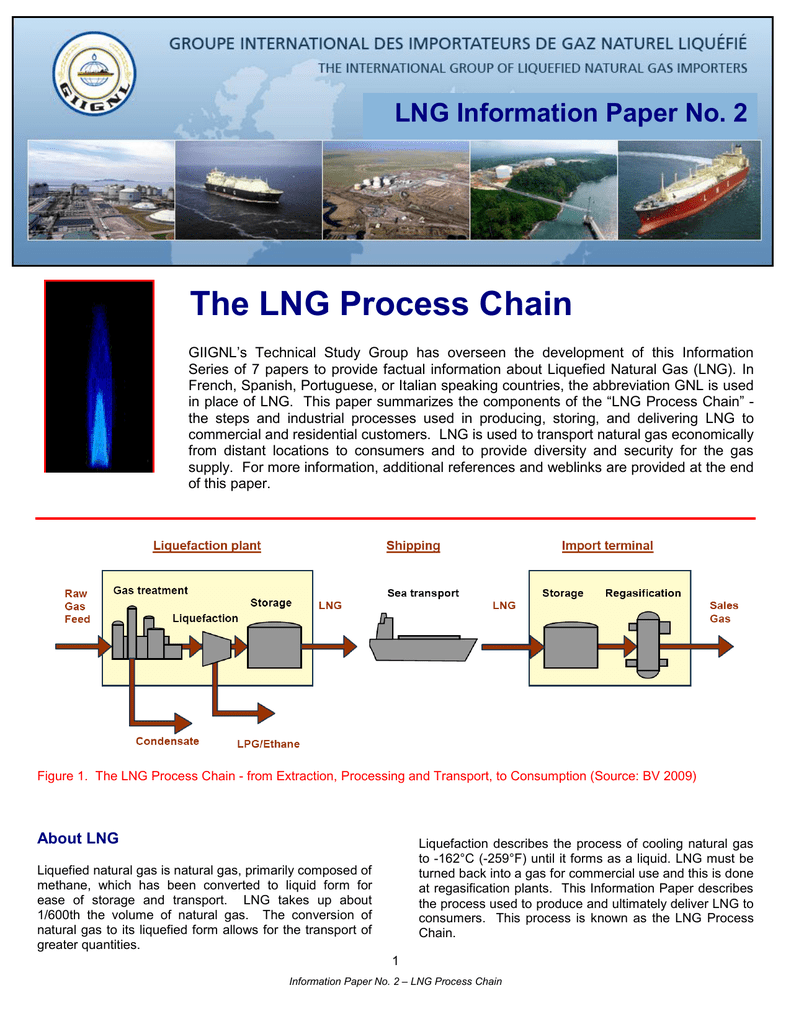
The LNG Process Chain - GIIGNL The International Group of
After making simple simulations mimic real process, variables were transferred to real process simulation. Optimization- Refrigerant composition . Optimization- Compressor work. Restriction needed- Heat transfer area. All cells in LNG HX must have equal area. Restriction needed- Second law of thermodynamics. Check temperature of streams. Utilities
Process flow of a typical LNG receiving and regasification ...
Process Flow Diagram Guide - Understand the historical purposes and benefits of process flow diagrams. Want to make a process flow diagram of your own? Try Lucidchart. It's quick, easy, and completely free.
Process selection and recent design innovations for LNG ...
3 Flow Diagram for a Typical LNG Plant. 4 LNG (Liquefied Natural Gas) Basics Combustible mixture of hydrocarbons Dry VS. Wet NGL Extraction Dehydration/Scrubbing Liquefied Natural Gas Target temperature for Natural gas:-260°F Reduces volume by a factor 600.

Process-Flow-Diagram-PID-Nitrogen-Generation-Membrane-Package ...
There are more than 110 liquefied natural gas (LNG) facilities operating in the U.S. performing a variety of services. Most of these facilities store LNG for "peak shaving," where the LNG is vaporized and transported in gas transmission or gas distribution pipelines for periods of peak demand. ... Process flow diagram and corresponding heat and ...
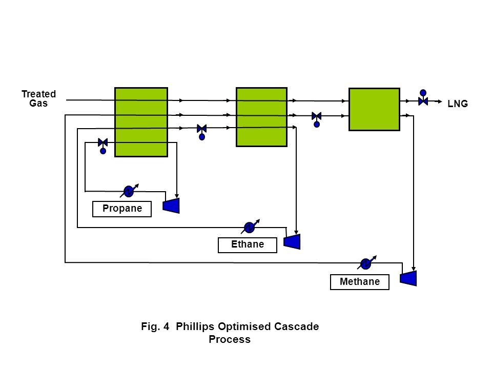
Fig. 1 LNG Block Flow Diagram - ppt video online download
3 Natural Gas Production. 3.1 Introduction. 3.2 Darcy and non-Darcy Flow in Porous Media. 6 Liquefied Natural Gas (LNG). 6.1 Introduction1. 6.2 The LNG Process. Figure 1-7 Phase diagram. Temperature. Clearly, the natural gas phase envelope can be very different depending on its source.
Optimized process schemes for LNG (LBG) production | GASP
Lentransgaz [34] developed new natural gas liquefaction equipment that uses the pressure energy to liquefy the natural gas without an external energy source. This investigation focuses on the LNG generation process during the transients in NG flow.
Atlantic LNG Train 4 “The World's Largest LNG Trainâ€
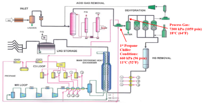
Liquefaction Process A block flow diagram of the liquefaction process is shown in Figure 2. The first step in the process is removal of acid gases such as carbon dioxide (CO2) and hydrogen sulfide (H2S). CO2 would freeze at cryogenic process temperatures and H 2S must be removed to meet the LNG product specifications. Typical specifications for

Overview of LNG Technologies | OwnerTeamConsultation
Dec 18, 2018 · LNG Storage Tank. For small scale LNG regasification facility, where the capacity is about 1-2 MMSCFD which can generate power about 5-10 MW (as rule of thumb, 1 MMSCFD of gas can generate 5 MW power) or can be as high as 6 MMSCFD, vacuum insulated tank (VIT) is usually used. It is pressurized tank with design pressure of 0.6-0.1 MPa.

Flow diagram of LNG process | Download Scientific Diagram
The global demand of liquefied natural gas (LNG) has risen rapidly in recent years for the reasons of energy security and sustainable development. This has led to considerable recent research interests and efforts in the LNG production chain and associated risks in handling, storage, and transport of...
ENERGY SAVING OPPERTUNITIES IN NATURAL GAS LIQUEFACTION ...
Liquefied Natural Gas (LNG): Natural gas from which impurities like sulphur and carbon-dioxide Diagram about LNG Ships Membrane Tank Structure: Unlike independent tanks, membrane tanks This method of gassing up is called "Piston Flow Method". In this the lighter specific gravity LNG...
University of Groningen The developing role of gas in ...
•At atmospheric pressure LNG has a temperature of about –162ºC •LNG contains about 85-95 % methane •LNG is colorless, odorless, non-corrosive and non-toxic •Evaporated LNG can displace oxygen and cause human suffocation •Flammability range, 5-15 vol % concentration in air •Autoignition temperature, 540 C 5 LNG is a cryogenic liquid

Simplified process flow diagram of AP-X LNG process ...
Process Flowchart This is a diagram that analyzes and illustrates the overall flow of steps involved in the production of a service or product. Finalizing procedures You can use the chart to create your final SOPs. These provide details about the tools and methods used in a process.
Process selection and recent design innovations for LNG ...
The APCI C3/MR Process – Part 2: An In-plant Review of the ...

Liquid Natural Gas Process in PT Badak NGL

16 Chemical manufacturing process flow chart ideas | process ...
Process selection and recent design innovations for LNG ...
0 Response to "39 lng process flow diagram"
Post a Comment