38 liftmaster wiring diagram sensors
Liftmaster Myq Wiring Diagram Liftmaster Myq Wiring Diagram feature, the MyQ® Smartphone Control, and any other MyQ® devices are to be used installation and operating garage door opener to avoid entanglement. . Garadget's wires will have to share the terminals with the existing wires ( MyQ and AssureLink models from LiftMaster, Chamberlain and. This video demonstrates how to wire photoelectric sensors to a LiftMaster gate operator.Additional Resources:Technical Support: http://bit.ly/ChamberlainTech...
Liftmaster And Genie Garage Door Opener Sensor Eye Issue. Replacing The Safety Sensors On A Garage Door Opener You. Garage Door Opener Repair And Troubleshoting. Liftmaster Garage Door Opener Troubleshooting Sensors Replacement. Safety Sensor Eyes For Liftmaster Chamberlain Sears Craftsman. See also Spanakopita Recipes Puff Pastry.
Liftmaster wiring diagram sensors
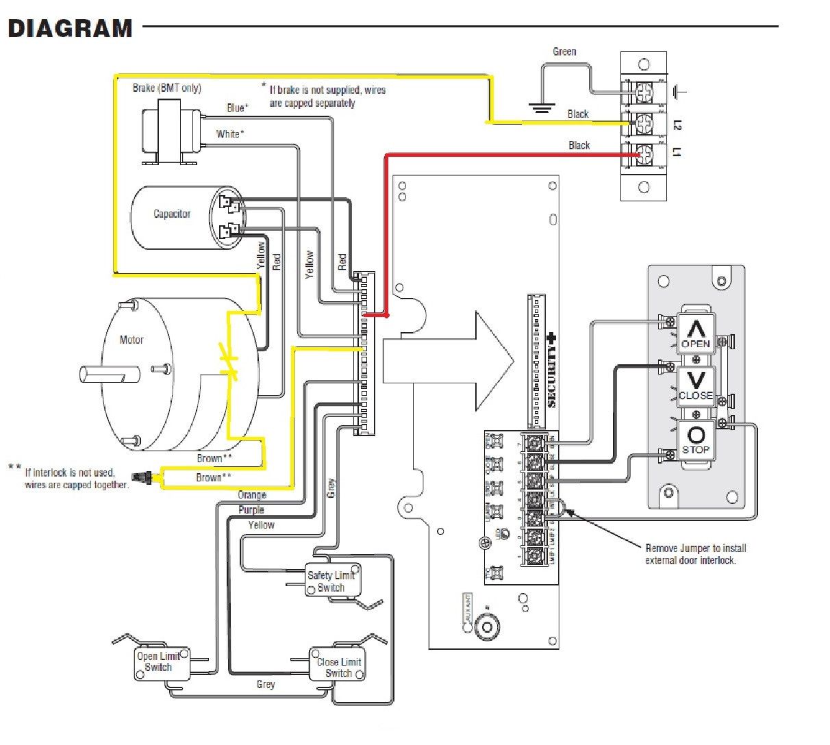
The AC 1/2hp DC garage door opener, wiring diagram for harnesses have a high voltage and low voltage wire harnesses that connect to different components in the operator, below is a description of which wires connect to which components. See an image of the wiring diagram. Liftmaster Wiring Diagram Sensors. Collection of liftmaster wiring diagram sensors. A wiring diagram is a simplified traditional pictorial depiction of an electric circuit. It shows the parts of the circuit as streamlined shapes, and the power and signal connections between the devices. A wiring diagram generally offers info concerning the family member setting as… Collection of liftmaster garage door sensor wiring diagram. A wiring diagram is a streamlined standard pictorial representation of an electric circuit. It reveals the components of the circuit as simplified forms, and the power and also signal links between the devices.
Liftmaster wiring diagram sensors. Detached Garage Wiring Diagram. Apollo Gate Opener Wiring Diagram. Elite Gate Opener Wiring Diagram. Sliding Gate Opener Wiring Diagram. Photocell Sensor Wiring Diagram. Honeywell Co2 Sensor Wiring Diagram. 4 Wire O2 Sensor Wiring Diagram Bmw. Mighty Mule 350 Gate Opener Wiring Diagram. 4 Wire O2 Sensor Wiring Diagram Toyota. Liftmaster Wiring Diagram Sensors | Manual E-Books - Liftmaster Garage Door Opener Wiring Diagram. Wiring Diagram consists of numerous in depth illustrations that present the relationship of assorted items. It consists of directions and diagrams for different kinds of wiring techniques and other items like lights, windows, and so on. Photoelectric Sensors for open or close cycle Edge Sensor for open or close cycle Edge Sensor for open or close cycle Photoelectric Sensors for open or close cycle Control Stations Jumper N.C. Expansion Board (Optional Accessory) (see below) PLUG-IN LOOP DETECTOR Model LOOPDETLM PLUG-IN TRANSFORMER Control Station Photoelectric Sensors for ... Complete kit includes: Sending sensor (with an amber LED), receiving sensor (with a green LED), 2-conductor wire, (5) wire connectors, (2) wingnuts, and (2) 1/4-20" round head bolts. Check the manual or replacement parts diagram for specific part information before ordering to ensure compatibility.
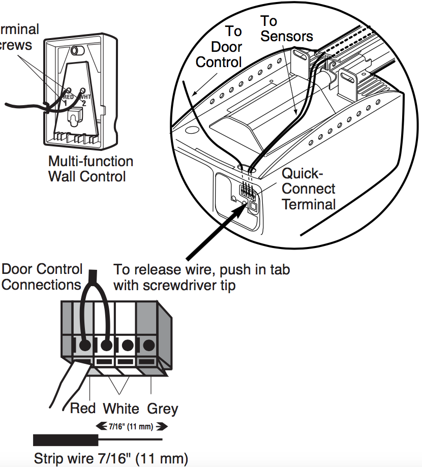
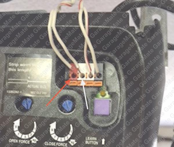
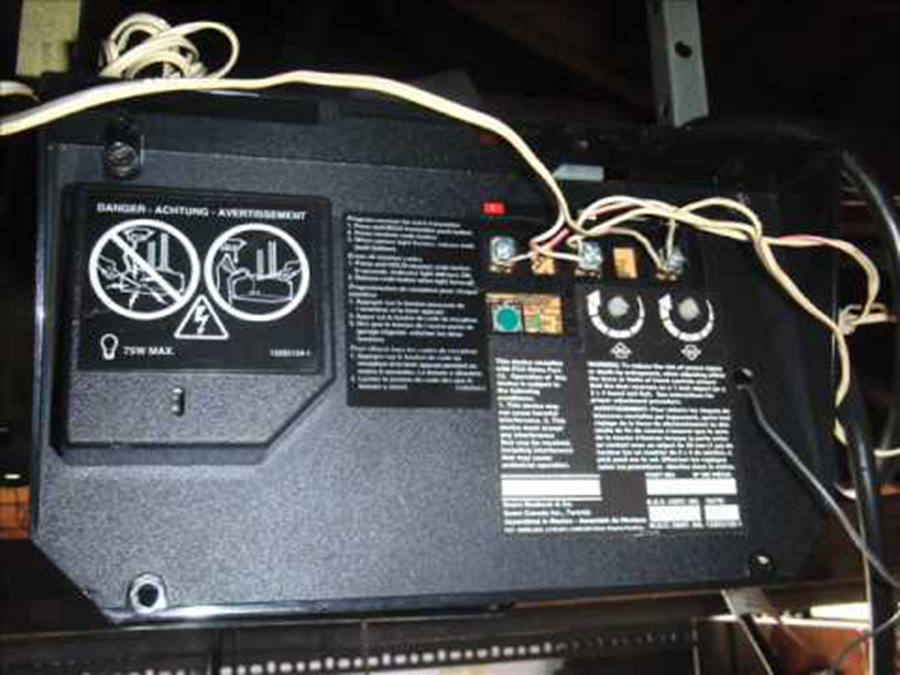
The Chamberlain Group LLC, the corporate parent company to LiftMaster, Chamberlain, Merlin and Grifco, is a global leader in access solutions and products. We design and engineer residential garage door openers, commercial door operators and gate entry systems. Read our story. If you look at the wires from the sensors you will find one wire from each sensor is solid white and the other is white with a black tracer. View and Download Chamberlain DH wiring diagram online. Locksensor (D1 Wiring). DH Accessories pdf manual download. Also for: Dj, Liftmaster dh, Liftmaster dj, Liftmaster dh/j. Sensor will stop the operator. LiftMaster Wiring Diagram Model RSL12U EY 1 Press and hold STOP... ...then press and hold CLOSE... ...then press and hold OPEN until "Er" shows. CODE SEQUENCE NUMBER The first number shown is the most recent code (example: "01"). The display will show the sequence of codes that occurred starting with "01" and going up to code "20". CODE NUMBER Liftmaster Garage Door Opener Wiring Diagram, Liftmaster Garage Door Sensor Wiring Diagram Dandk Organizer, Chamberlain Liftmaster Garage Door Opener Troubleshooting, Garage Door Opener Repair and Troubleshoting, Bill's Corner: Update on the 1979 Mark V Garage Door
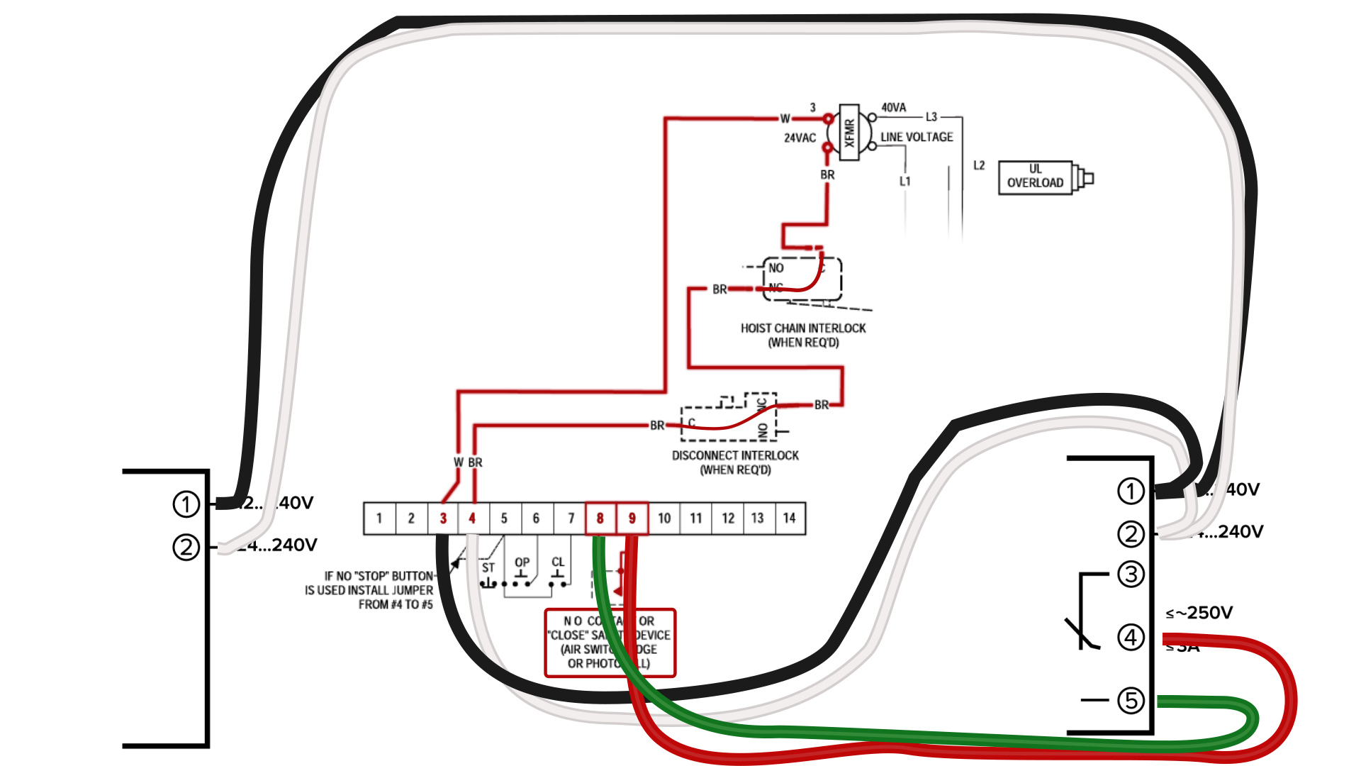
PDF. Postcolonial Studies in the Twenty-first Century: A Book Review Article of Literature for Our Times & Reading Transcultural Cities Alejandra Moreno Álvarez Latest information about coronavirus (COVID-19), online services and MyAccount, customer services and how to make a complaint. Model 3: Programming instructions for the GK-BX Wireless Intellicode Keyad. Works with Genie systems using Intellicode 1 and Intellicode 2 controls. Intellicode 1 refers to all systems made from 1995 to Present, with the exception of 2011 and 2012. Chamberlain Liftmaster Cb11 Control Panel Wiring Diagram Manualzz. Garagemate bluemate labs inc single phase wiring diagram sw470 rsl12v manual how to fix 5 common garage door medium duty logic operator liftmaster chamberlain 41a5021 4m 315 41a5034 safety sensor kit electric opener stopped yolink 41a4252 6g circuit board wire multiple 3 on control stations remotes custom doors professional ...
LiftMaster - How to Install Photoelectric Sensors to Gates
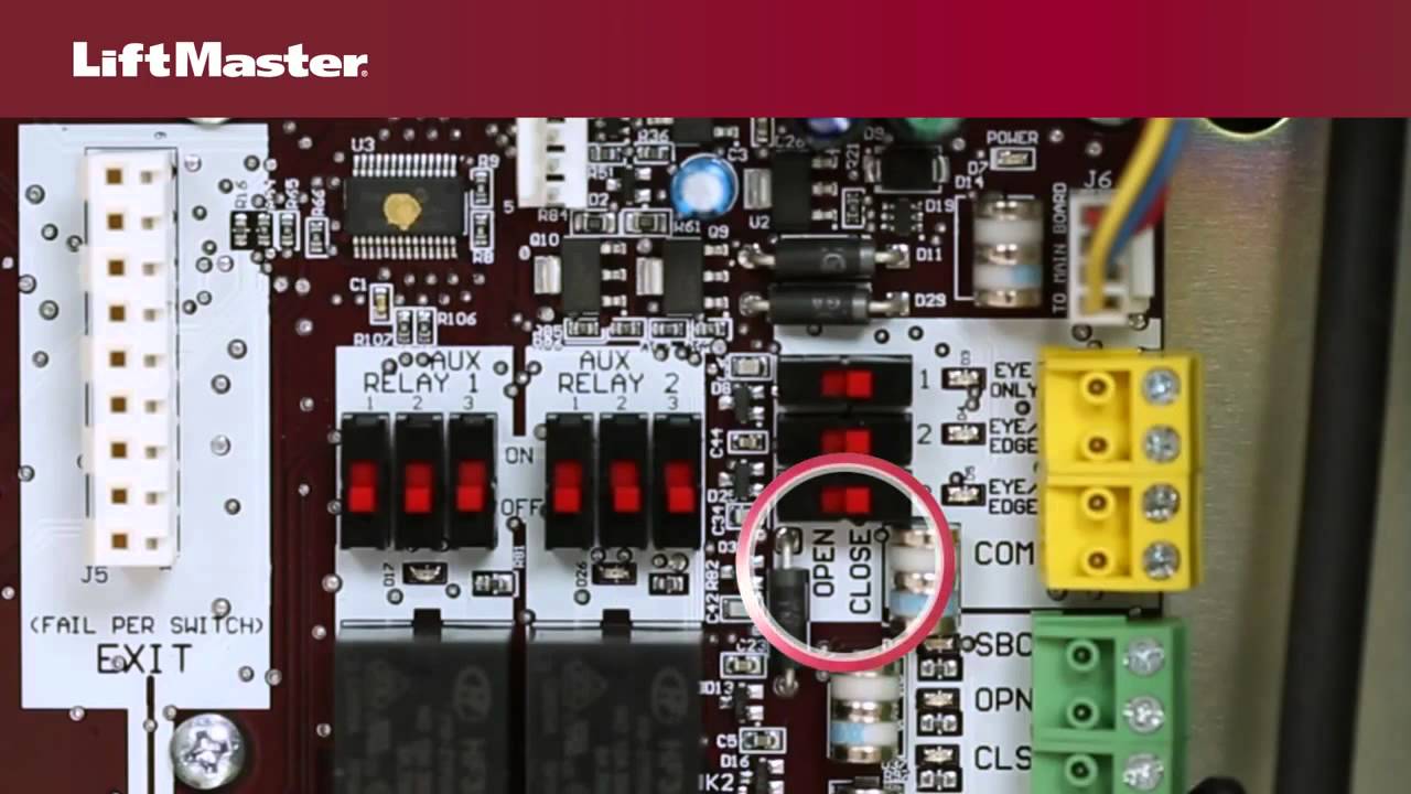
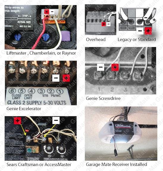
Wiring safety reversing sensors, which ensure a garage door automatically reverses before contacting anything in its path, starts by identifying terminal-type. Correctly connecting safety reversing sensors begins with identifying the type of terminal on the opener motor head, which is on the same side as the LEARN button.
How to troubleshoot a Medium Duty Logic operator | LiftMaster ...
It all depends on circuit that's being assembled. As stated previous, the lines at a Liftmaster Wiring Diagram represents wires. At times, the cables will cross. But, it does not mean link between the wires. Injunction of two wires is generally indicated by black dot in the junction of 2 lines.

✅Wiring A Chamberlain Garage Door Opener
Chamberlain Garage Door Wiring Diagram Automotive Schematic. 041a5034 Safety Reversing Sensor Kit Parts Liftmaster. Liftmaster 41a4373a Garage Door Opener Safety Eyes. Stanley Opener Sensor Wiring Diagrams Daily Update Diagram.
Nold
Variety of liftmaster wiring diagram you'll be able to download free of charge. Please download these liftmaster wiring diagram by using the download button, or right click on selected image, then use Save Image menu. Wiring diagrams help technicians to find out the way the controls are wired to the system.
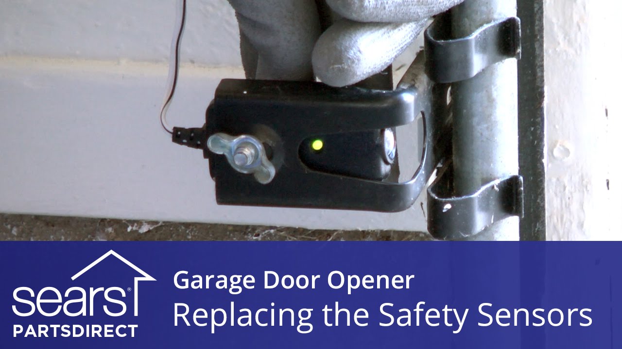
Replacing the Safety Sensors on a Garage Door Opener
Liftmaster 41a5021 Wiring Diagram Liftmaster 41a5021 Wiring Diagram Connect the two wires from the Garadget's blue terminal to the red and white terminals on the garage door opener. Garadget's wires will have. Find solutions to your liftmaster wiring diagram sensors question.
GarageMate - BlueMate Labs, Inc.
Liftmaster Wiring Diagram Sensors 23.11.2018 2 Comments Wiring safety reversing sensors, which ensure a garage door automatically reverses before contacting anything in its path, starts by identifying terminal-type. Setting the UP Position on Garage Door Travel Limits for Openers with Quick Connect Plug-In Terminals.

Liftmaster Elite Series 8550 Wall Mount Garage Door Opener
A wiring diagram is an easy visual representation with the physical connections and physical layout associated with an electrical system or circuit. View and download chamberlain dh wiring diagram online. View and download chamberlain elite series wiring diagram online. Variety of chamberlain garage door sensor wiring diagram.
1D8075 Commercial Door Operator User Manual 01-36811.indd ...
View and Download Chamberlain Elite SL3000UL owner's manual online. Vehicular Slide Gate operator. Elite SL3000UL gate opener pdf manual download.

WIRE HIDE Premium Garage Door Sensor Wire Cover Protector Kit ...
Dual air/fuel sensors were used to monitor fuel mixture after combustion and continual adjustments were made to reduce exhaust gas emissions. The EZ30D had a direct ignition system with an individual ignition coil for each cylinder (i.e. ‘coil-on-plug’), eliminating the need for a distributor and spark plug wires.
How to Install Omron E3JM Photo Eyes on Powermaster Operators ...
5 TROLLEY MAXIMUM DOOR AREA (SQ. FT.) MODEL T STANDARD SECTIONAL 24 ga. 22 ga. Steel Alum. Doors---285 350 500 625---Fiberglass Doors---310 400 560 640 20 ga. Steel

41a4373a Liftmaster Safety Sensor Kit
Diagram chamberlain garage door opener sensor wiring full version hd quality genie sensors elsewhere all about circuits garagemate bluemate labs inc liftmaster 41a5034 safety kit hbw0777 can i use existing wireing for ny new if so what wires go where have a and together blue repair troubleshoting 041a5034 parts overhead troubleshooting ...

Mimolite Garage Door closes from app but not from button ...
Safety sensors are not installed, connected, or wires may be cut. Inspect sensor wires for a disconnected or cut wire. 1; 2: The garage door opener will not close and the light bulbs flash. There is a short or reversed wire for the safety sensors. Inspect safety sensor wire at all staple and connection points, replace wire or correct as needed ...

Garage Door Opener Repair and Troubleshoting
Photoelectric Sensors for open or close cycle Photoelectric Sensor for open or close cycle Edge Sensor for open or close ... Use ONLY LiftMaster approved entrapment protection devices (refer to the ... CSL24UL Wiring Diagram ...

How to-Install a Liftmaster 8500 Door Opener • High-Lift Door Inc
Collection of liftmaster garage door opener wiring diagram. A wiring diagram is a basic graph of the physical links and also physical layout of an electrical system or circuit. Liftmaster partner product support. The rjo will not close the garage door and diagnostic flashes 9 times or 3 up and 5 down. How to install safety sensors correctly.

How to replace your drive gears in your Liftmaster Sears ...
According to earlier, the traces in a Liftmaster Garage Door Opener Wiring Diagram signifies wires. Occasionally, the cables will cross. However, it does not imply link between the wires. Injunction of 2 wires is usually indicated by black dot in the intersection of 2 lines.
1D8075 Commercial Door Operator User Manual 01-36811.indd ...
WIRING DIAGRAM Model LA400UL CODE MEANING SOLUTION 31 Main control board has experienced an internal failure. ... external entrapment protection devices such as photoelectric sensors or edge ... LA400UL Wiring Diagram LiftMaster ...
Installation with Liftmaster Opener - Wiring Openers ...
The Chamberlain Group LLC, the corporate parent company to LiftMaster, Chamberlain, Merlin and Grifco, is a global leader in access solutions and products. We design and engineer residential garage door openers, commercial door operators and gate entry systems. Read our story.
GarageMate - BlueMate Labs, Inc.
Collection of liftmaster garage door sensor wiring diagram. A wiring diagram is a streamlined standard pictorial representation of an electric circuit. It reveals the components of the circuit as simplified forms, and the power and also signal links between the devices.

Pin by Bkgoulet on Garage door sensor | Garage doors, Garage ...
Liftmaster Wiring Diagram Sensors. Collection of liftmaster wiring diagram sensors. A wiring diagram is a simplified traditional pictorial depiction of an electric circuit. It shows the parts of the circuit as streamlined shapes, and the power and signal connections between the devices. A wiring diagram generally offers info concerning the family member setting as…
Select Products - Parts - Garage Door Opener Parts ...
The AC 1/2hp DC garage door opener, wiring diagram for harnesses have a high voltage and low voltage wire harnesses that connect to different components in the operator, below is a description of which wires connect to which components. See an image of the wiring diagram.

Need some help figuring out how Electric Gate arm sensors ...
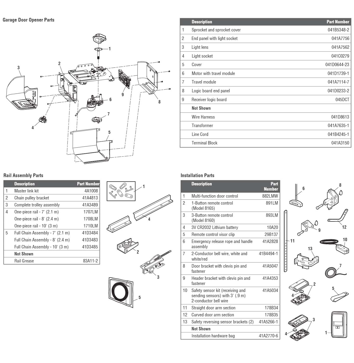
LiftMaster 8160 Garage Door Opener Parts Diagram and List ...
Select Products - Parts - Garage Door Opener Parts ...
Installing Two Sets of Photocells to the CB1 Control Panel ...
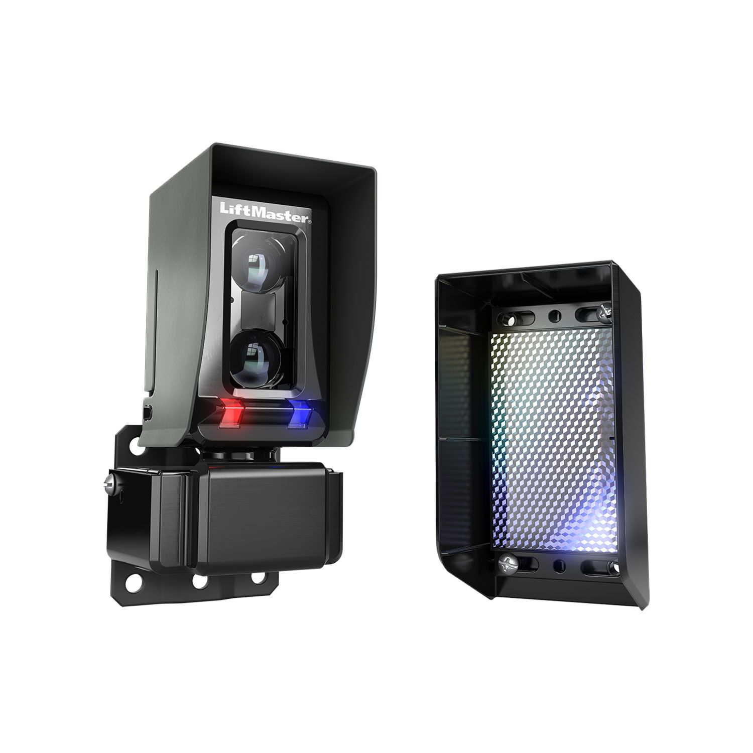
LiftMaster Monitored Retro-Reflective Photo Eyes with Built-In Heater

Awesome Genie Garage Door Opener Sensor Wiring Diagram ...
LMRRUL and LMTBUL: How and when to wire up the heater ...

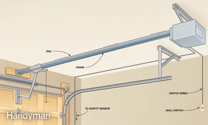
Garage Door Operator Prewire and Framing Guide

Amazon.com: Liftmaster K74-18379 Replacement Hall Effect ...
Garage Door Openers | Installation Garage Doors | Garage Door ...
My Garage Door Opener Is Flashing, But Does Not Fully Close

How to Install the LiftMaster Commercial Protector System, Model CPS OPEN4

Wiring Diagram for Liftmaster Garage Door Opener | Liftmaster ...

Troubleshooting your Liftmaster 8500 Door Opener • High-Lift ...
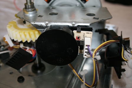
How to replace your drive gears in your Liftmaster Sears ...

WIRE HIDE Premium Garage Door Sensor Wire Cover Protector Kit ...

Wiring diagrams, Standard control box, Attach to outlet metal ...
7 Steps to Bypass Garage Door Sensors
0 Response to "38 liftmaster wiring diagram sensors"
Post a Comment