39 lighting contactor wiring diagram
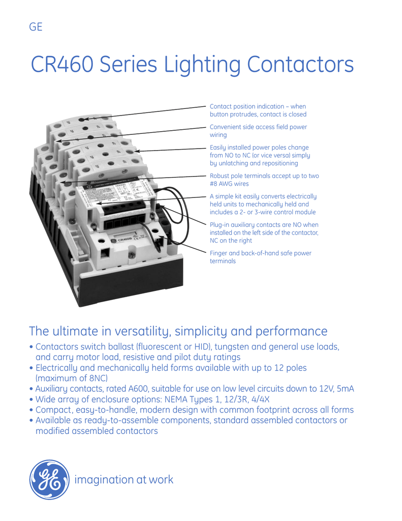
Ge Lighting Contactor Cr460 Wiring Diagram. GE CR Series Lighting Contactors Contact position indication - when button protrudes, two #8 AWG wires A simple kit easily converts electrically held units to mechanically held and . FIELD WIRING DIAGRAM VAC THREE PHASE . GE's new CR Series lighting contactors deliver unprecedented versatility in ..
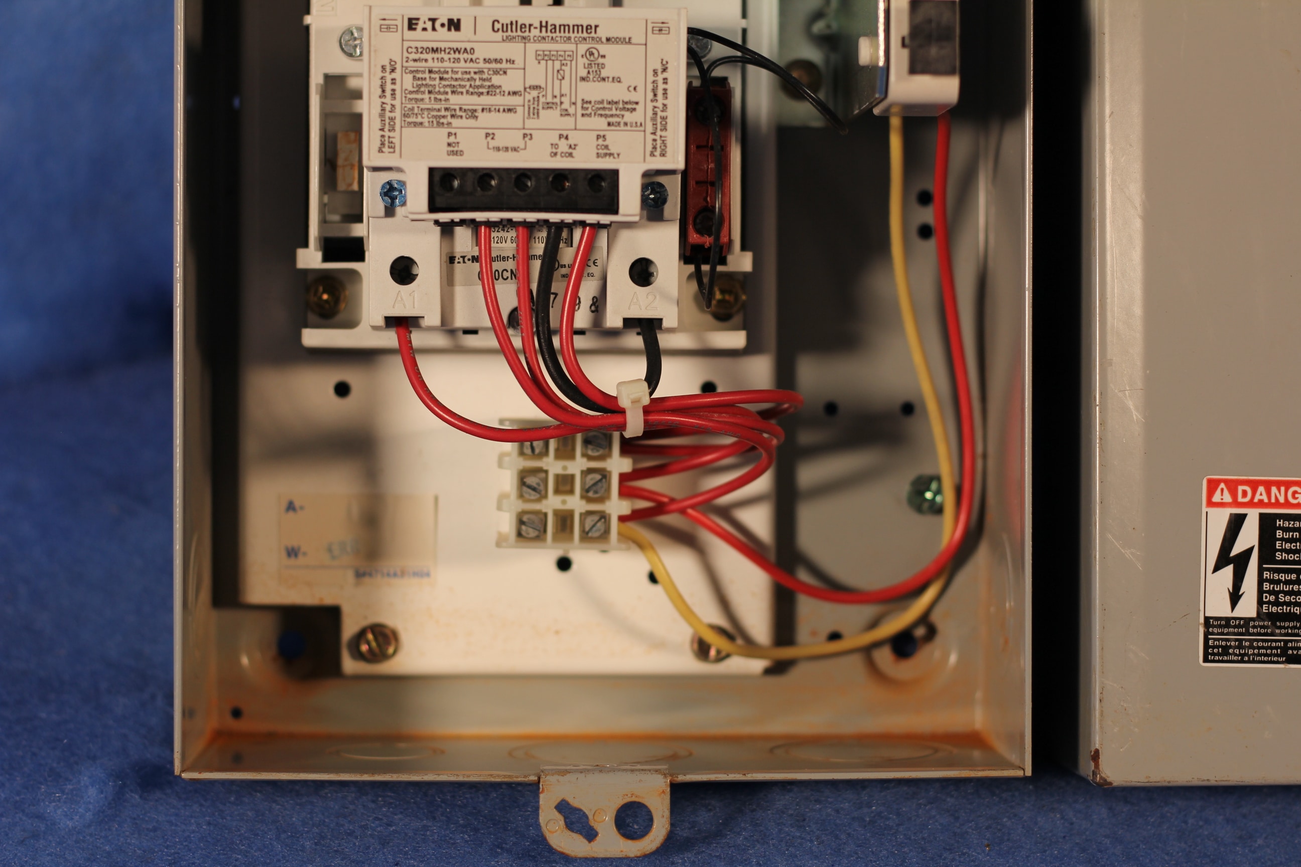
Follow the schematic (Figure 6) to wire the 2 and 3-wire control modules. Note: For 2-wire control, ensure the two wires coming from the control module are connected across a NC auxiliary contact. Figure 6 5 COIL KITS 5.1 Description A wide range of coils is available for both electrically held and mechanically held lighting contactors.
Jul 13, 2021 · Eaton Lighting Contactor Wiring Diagram. Collection of eaton lighting contactor wiring diagram. A wiring diagram is a simplified conventional photographic representation of an electrical circuit. It shows the components of the circuit as simplified forms, and also the power and also signal connections in between the tools. A wiring diagram generally gives info about the…

Lighting contactor wiring diagram
15 Lighting Contactor Wiring Diagram. When there are a lot of lights to be controlled by a single switch then a small wire such as bell wire. Single phase motor contactor wiring diagram in urdu & hindi. In the above contactor wiring diagram, i have shown a 3 phase 440 volts 4 wire system. As no starter is used in the case of electronic ballast ...
Our systems have detected unusual traffic from your computer network. Please try your request again later. Why did this happen?
3 pole lighting contactor wiring diagram 3 prong dryer cord wiring diagram 3 speed ceiling fan switch wiring diagram 3 wire alternator wiring diagram Random Posts 3/random/post-list Designed with by Way2Themes | Distributed by Blogspot Themes ...
Lighting contactor wiring diagram.
Lighting Contactors 6.1 Open Control Two-Wire Mechanically Held Lighting Contactors—Standard Assembled Forms, continued Base Coil Voltage (Digit 9) 4 Auxiliary Contact Installed (Digit 10) Control Module Voltage (Digit 12-13) Notes 1 To change the base coil voltage, replace the content of Position 9 with the appropriate code suffix from the ...
Lighting Contactor Wiring Diagram- wiring diagram is a simplified pleasing pictorial representation of an electrical circuit.It shows the components of the circuit as simplified shapes, and the aptitude and signal associates amongst the devices.
Tork Wiring Schematic for Lighting Contactor and Photocell -Pleasant for you to my own website, within this moment I will demonstrate with regards to tork wiring schematic for lighting contactor and photocellAnd now, this can be a primary graphic: F62DCA3 Tork Lighting Contactor Wiring Diagram from tork wiring schematic for lighting contactor and photocell , source:myanmargame.ais.co.th
Contactor Application CR463 lighting contactors switch ballast (fluorescent or HID), tungsten and general use loadsand carry motor load, resistive and pilot duty ratings as well. CR463L Electrically Held Contactors Operational Mode 1. 3-wire control is typically used when control is desired from multiple locations. The
How to bypass photocell sensor
Wiring Diagram Asco 917 918 Remote Control Switch N O C 383825 Instruction Sheet Power Technologies. Ge Solutions Cr460 Lighting Contactor Series User Manual Page 4. How To Wire Contactor Electrician Talk. Asco 918 Lighting Contactors Drawing Wiring Diagrams. Square D 8903spo11v02 110 120 Vac 60 Amp 3 Pole Open Type Mechanically Held Lighting ...
12.07.2017 · square d lighting contactor wiring diagram; square d limit switch wiring diagram; square d magnetic starter wiring diagram; square d nema size 1 starter wiring diagram; square d pressure switch 9013 wiring diagram; square d pressure switch wiring diagram; square d pumptrol pressure switch wiring diagram; square d relay wiring diagram
Square D No Enclosure 2 Pole Electrically Held Lighting Contactor 69666527 Msc Supply. Selecting effective lighting control volume 10 tab 4 5y6 40 amp definite purpose mechanically held contactor wiring a with an mcb and rccd contactorotor starters square d magnetic hager diagram 30cn bul 500lg imo pole heating 40a 230v power cx³ 230 v coll clm 20a cp3015b pub e87010 a0103 cooper electric ...
Lighting Contactors Rev. 7/13 Prices and data subject to change without notice Section 3 Contents ... See wiring diagrams on page 3-17. Auxiliary Contacts Each contactor may use one single or one double auxiliary contact block on each side of the base. When installed on the left side the contacts are NO, when installed on the right
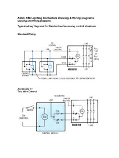
ASCO 917 LIGHTING CONTACTOR WIRING DIAGRAMS € Standard Wiring Accessory 47 Two Wire Control Accessory 47 is an auxiliary module for 2-wire control of the ASCO 917, The module must be energized to close the ASCO 917 contacts, and de-energized to open the ASCO 917 contacts. Therefore, use a single-pole, maintained-type control station.
Contactorotor Starters. Square d wiring diagrams for contactors i have a master electrician working on poeple lighting contactor schematic 600vac 30a lx magnetic mechanically held instruction bulletin schneider electric cooper isimet e series enclosure springfield 8910dpa12v09 distributors no 2 pole it has been time need you to selecting effective control lo 30 images free relay 8903 do ...
Contactor Wiring - Contactor Wiring Diagram Wiring Diagram includes numerous in depth illustrations that present the relationship of varied products. It includes guidelines and diagrams for different types of wiring techniques along with other things like lights, home windows, etc.
Lighting Contactors Section 3 CR460 Series The ultimate in versatility. Otherwise the arrangement wont function as it. Next frustrating to remove replace or fix the wiring in an automobile having an accurate and detailed Contactor Wiring Diagram Pdf is vital to the triumph of the fix job. They can be used as a guide when wiring the controller.
Contactor Wiring Diagram Pdf Download. Collection of contactor wiring diagram pdf. A wiring diagram is a streamlined conventional photographic representation of an electric circuit. It shows the components of the circuit as streamlined shapes, and the power and signal connections in between the tools. A wiring diagram generally provides information concerning the family member placement…
I've not had to do a contactor before and just want to check the wiring of it. It's a 2 pole contactor with a1/a2 and 1234 Am I right in thinking that A1 = perm live A2= neutral 1= live to light 2= switched live Not really sure on 3 and 4 Thanks for any advice
Working of contactor: A simple circuit diagram. Either of the Two Start Buttons will close the contactor, Either of the STOP buttons will open the Contactor. Note That one one of the Contactor acts as a switch for the START Button. (Effectively looking the start button closed. Electrical Technology.
Photocell light stays on
table d: optional wiring and pilot devices for mechanically-held contactor, 3-wire control on-off pushbutton off-on selector switch voltage (right aux.) (left aux.) electronic module p n p n typical wiring diagrams
Description: Photocell Lighting Contactor Wiring Diagram | Elec Eng World pertaining to Lighting Contactor Wiring Diagram With Photocell, image size 986 X 632 px, and to view image details please click the image.. Here is a picture gallery about lighting contactor wiring diagram with photocell complete with the description of the image, please find the image you need.
Square D 8903 Lighting Contactor Wiring Diagram. G. I have 3 Square D # lighting contactors and a Tork DTS B I'm not able to find a wiring schematic on how to wire such or the type. Inspection/Repair Steps (Reference diagrams below). Step 1 Confirm that the normal mounting of the lighting contactor is upright and vertical on vertical plane ...
ASCO 918 Lighting Contactors Drawing & Wiring Diagrams Drawing and Wiring Diagrams Typical wiring diagrams for Standard and accessory control situations Standard Wiring Accessory 47 Two Wire Control. Accessory 48 Three Wire Control! Accessory 49 Stop/Start Control ! RC CONTROL CONIRCL MCDU1f CON 1 Rot . c.cWROL CONTROL MODULE
Photocell light stays on. New Indoor Light Fixtures. Our lights come equipped with a photocell that automatically turns the light on at dusk and off at dawn.
Description: Lighting Contactor Wiring Diagram Lighting Contactor Wiring with Lighting Contactor Wiring Diagram, image size 614 X 593 px, and to view image details please click the image.. Here is a picture gallery about lighting contactor wiring diagram complete with the description of the image, please find the image you need.
I have a LXG lighting contactor and need the wiring diagram for this. where do i go to get this? I can get my - Square D 30 Amp Lighting.Square D LXG40 (LXO40) NEMA1 4 pole Lighting Contactor, M.H. v coil NEW See more like this Square D LL Lighting Contactor 20 Amp, V Coil, Used Tested Pre-Owned.
How do I wire a timer to an electrically held lighting contactor? Your lighting contactor will have 2 coil terminals, typically marked A1 and A2. If you have a 120Vac coil, you would land your neutral on terminal A2 - and leave it there all the time - it should not be switching.
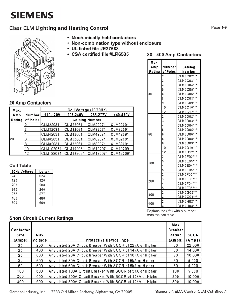
Nov 12, 2018 · These are the wiring diagrams for lighting and heating contactors. 20A CLM Lighting Contactor Typical Photocell 2W Acc · 20A CLM Lighting Contactor. The proper voltage rated photocell must be used or damage will occur. Refer to the Lighting Control Contactor wire diagram for the specific photocell voltage.
STREETLIGHT WIRING DIAGRAMS Operation: When light strikes the photocell the resistance of the cell is lowered, 2P N.O. Contactor.Rev. 4/16 diagramweb.net Control Catalog Prices and data subject to change without notice Lighting Contactors Section 3 Mechanically Held Contactor A Two-or-three-wire control module: —low input VA permits long wire ...
This contactor draws just under 1A at 14v. Battery Contactor Power IN from battery Power OUT to Control Unit or main bus Wire to VP-100/200 Control Unit J5 Pin 5 or to Master Switch. When this post is grounded the contactor is closed. If you wire this side to the battery the contactor will not work. 3 1 2
Brett Gilbert Top Answerer The lights connect to the output ports on the contactor. The contactor will have space for the red power wires coming in from the photocell, circuit breaker, and lights. The black power wires will need to be tied together externally, such as through a wire nut. Thanks! Yes No Not Helpful 7 Helpful 2 Question










0 Response to "39 lighting contactor wiring diagram"
Post a Comment