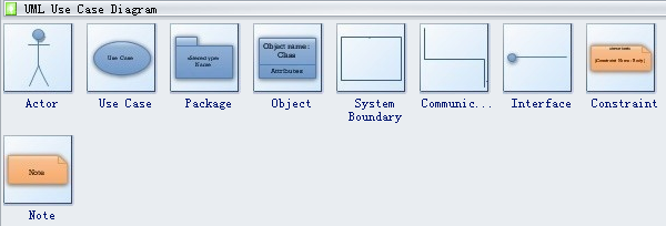
38 use case diagram notations
An actor is used in a use case diagram to describe the internal or external entities. Initial State Notation Initial state is defined to show the start of a process. This notation is used in almost all diagrams. The usage of Initial State Notation is to show the starting point of a process. Final State Notation
Use Case Diagram Notations — Use Case Diagram Notations. Use cases define interactions between external actors and the system to attain particular goals. A ...
A UML Use Case Diagram is a diagram that describes usage behaviors of a system from an outside user's point of view. Those usage behaviors are organized into units of use cases. Use Case Notation is used to describe a set of activities performed by actors on an object. When it is completed, a use case will yield a result that can be observed.

Use case diagram notations
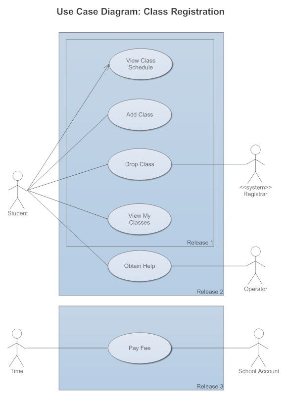
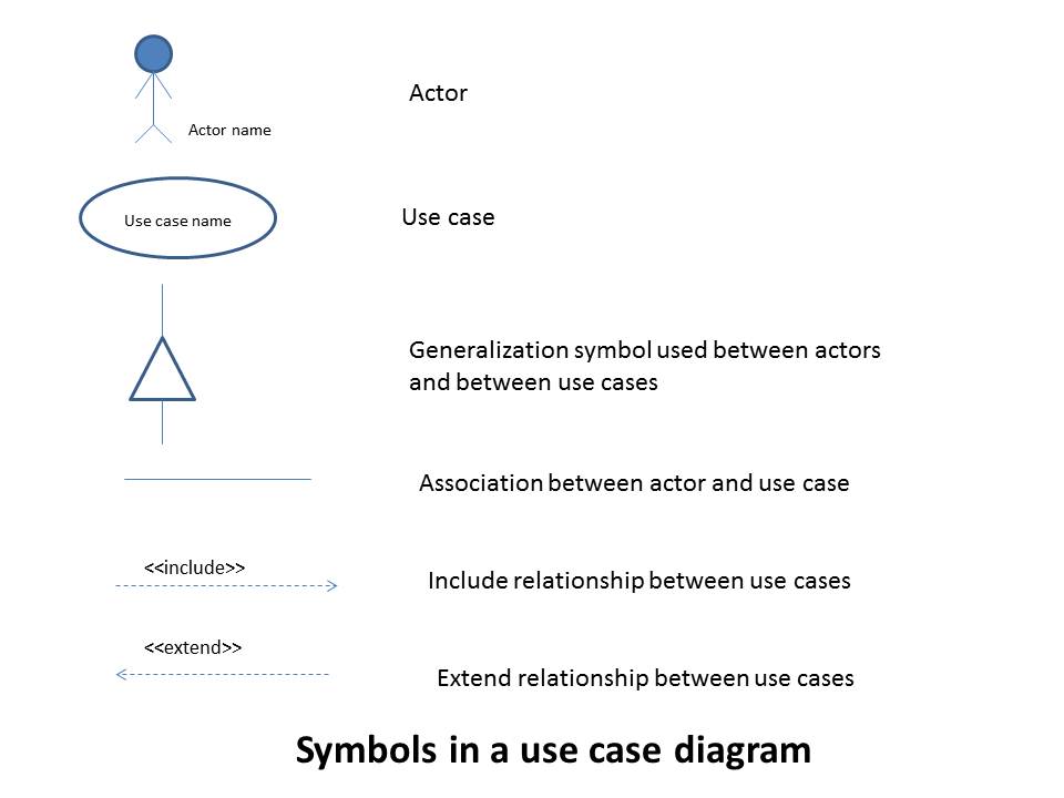
The notation for using a use case is a connecting line with an optional arrowhead showing the direction of control. 15 Use Case Diagram Notation. A use case diagram shows how use cases and actors relate to each other and gives a functional system overview. Basic use case diagram symbols and notations.
8 Oct 2021 — Use case diagrams are a way to capture the system's functionality and requirements in UML diagrams. · It captures the dynamic behavior of a live ...
A use case is a single unit of meaningful work. It provides a high-level view of behavior observable to someone or something outside the system. The notation ...
Use case diagram notations.
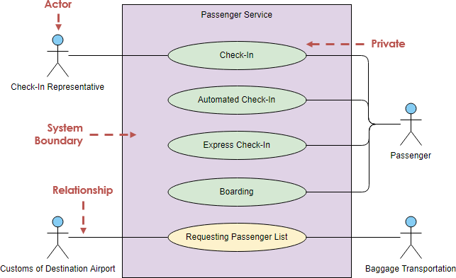
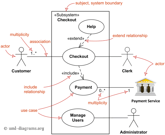
#2) Use Case: It represents a functional unit of a large application. Notation is horizontally shaped oval and is located inside the System boundary rectangle indicating that the use case applies to the mentioned subject. A specific use case can be referred to by other systems as well. So the system is not the owner of the use case.
How to create use case diagram 1. List main system functions (use cases) in a column: –think of business events demanding system’s response –users’ goals/needs to be accomplished via the system –Create, Read, Update, Delete (CRUD) data tasks –Naming use cases – user’s needs usually can be translated in data tasks 2.
A UML use case diagram is the primary form of system/software requirements for a new software program underdeveloped. Use cases specify the expected behavior (what), and not the exact method of making it happen (how). Use cases once specified can be denoted both textual and visual representation (i.e. use case diagram).
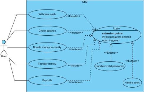
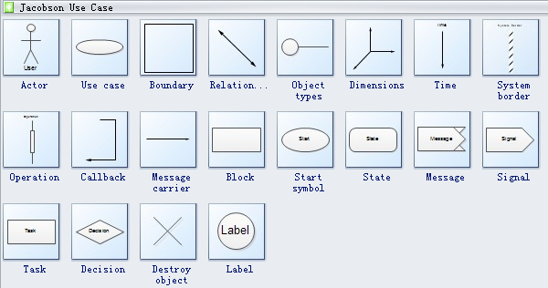
Use Case Diagram notations guide Use case diagram is a kind of UML diagram. Here is a list of Unified Modeling Language (UML) notations supported in a UML use case diagram: Use Case A use case represents a user goal that can be achieved by accessing the system or software application.
UML Class Diagram Notation When it comes to system construction, a class diagram is the most widely used diagram. UML Class Diagrams is a type of static structure diagram that is used for general conceptual modeling of the systematics of the application. Such a diagram would illustrate the object-oriented view of a system .
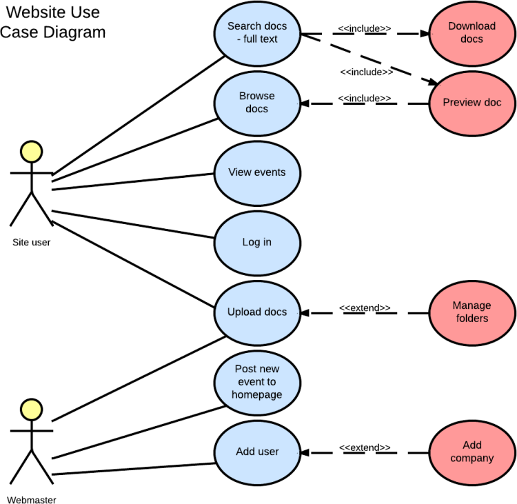
Use case diagram symbols and notation · Use cases: Horizontally shaped ovals that represent the different uses that a user might have. · Actors: Stick figures ...
Use case diagram is a behavioral UML diagram type and frequently used to analyze various systems. They enable you to visualize the different types of roles in a system and how those roles interact with the system. This use case diagram tutorial will cover the following topics and help you create use cases better. Importance of use case diagrams.
A use case diagram of a software system describes the functionalities to be implemented by the software system. It is at a relatively higher level of ...
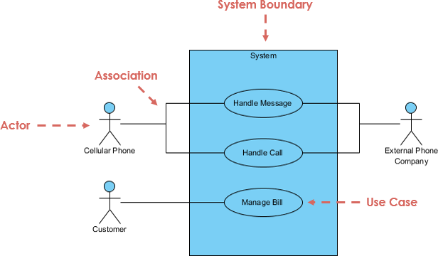
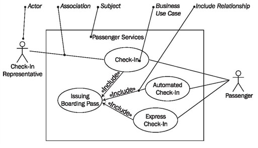
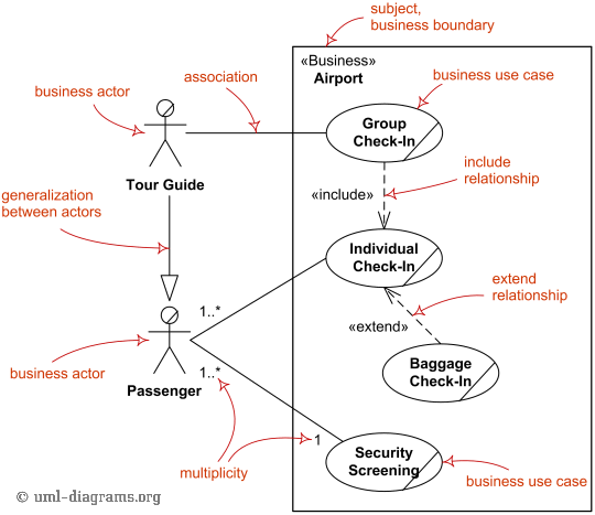
The subject (of use cases) is the system under design or consideration to which a set of use cases apply.The subject could be a physical system, software program, or smaller element that may have behavior, e.g. subsystem, component, or even class.. Subject is presented by a rectangle with subject name in upper corner with applicable use cases inside the rectangle and actors - outside of the ...
Basic Use Case Diagram Symbols and Notations ... Draw your system's boundaries using a rectangle that contains use cases. Place actors outside the system's ...
![PDF] Formal Specification of UML Use Case Diagram-A CASL based ...](https://d3i71xaburhd42.cloudfront.net/dcd8b0e7adc51256bcfcc584cff3c2d807fac507/4-TableI-1.png)










0 Response to "38 use case diagram notations"
Post a Comment