38 shear force and bending moment diagram problems and solutions pdf
(5.4), the shear force equation is : dM ( x ) a V (x ) = =− P (5.8) dx L These expressions for the bending moment and shear force can now be plotted against x to produce the Shear Force and Bending Moment Diagrams as Fig. 5.5: Lecture Notes of Mechanics of Solids, Chapter 5 3 P a Loading Diagram (1-a/L)P L Pa/L V(x) (1-a/L)P Shear Force ...
Shear force and bending moment diagram problems and solutions pdf Shear Force Diagram is the Graphical representation of the variation of Shear Force Over the cross-section along the length of the beam. With the Shear Force Diagram's help, we can identify Critical sections Subjected to Shear and design amendments to be made to avoid failure.
Write shear and moment equations for the beams in the following problems. In each problem, let x be the distance measured from left end of the beam. Also, draw shear and moment diagrams, specifying values at all change of loading positions and at points of zero shear.
Shear force and bending moment diagram problems and solutions pdf
The ability to draw shear force and bending moment diagrams on beam-like components is an important skill for mechanical engineering students. We found that some students had difficulty to draw effectively the shear force and bending moment diagrams during the course and even in their senior year.
The bending moment diagrams for concentrated forces are linear; that is, they have constant slope (they are of the form y = mx+c where m is the slope). These are most easily derived from the area under the shear force diagram. The area under the shear force diagram to the left of x = 0 is 0 so the point (0,0) is on the bending moment diagram.
CE 331, Fall 2007 Shear & Moment Diagrams Examples 2 / 7 2. Draw the shear and moment diagram due to dead load. Note the magnitude and location of the maximum bending moment, MD. 3. Calculate the moment due to live load, ML. We will assume that the maximum moment due to dead plus live loads (MD+L) occurs at the location of the maximum moment ...
Shear force and bending moment diagram problems and solutions pdf.
Construction of the Bending Moment diagram B C E V 6 ft 8 ft 10 ft 8 ft x a) M = 0 at point A because it is a pinned end with no applied bending moment. b) MB = Ma + (the area under the shear force diagram between A and B.) c) MB = 0 + (18 kips)(6 ft) = 108 kip-ft d) MC = MB + (the area under the shear force diagram between B and C.) e) MC = 108 kip-ft - (2 kips)(8 ft) = 92 kip-ft
4 Shear Forces and Bending Moments Shear Forces and Bending Moments 800 lb 1600 lb Problem 4.3-1 Calculate the shear force V and bending moment M A B at a cross section just to the left of the 1600-lb load acting on the simple beam AB shown in the figure. 30 in. 60 in. 30 in. 120 in. Solution 4.3-1 Simple beam Free-body diagram of segment DB ...
Complex Shear Force Diagram Practice Problems ... Shear Force and Bending Moment Diagrams . 9-2 Making a Shear Force Diagram _____ To determine the point where the supported truss is most prone to breakage, we use a shear force diagram to analyze the beam. The diagram starts at the zero point on both the left and ...
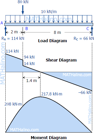
Construct the S.F. and B.M. diagrams and find the amount and position of the maximum B.M. over the beam. …. (Solved Book Problems) Problem 15, chapter - Shear Force and Bending Moment, Book - Strength of Materials by Dr. R K Bansal. - A beam of length 6 m is simply supported at its ends. It is loaded with a gradually varying load of 750 ...
Concepts of Traction and Stress In general, Traction is the distributed force per unit area acting at a point on any (external) surface of a body or a part of a body. Traction is a vector represented with a 3x1 matrix in 3D. Stress is a physical quantity that completely characterizes the distributed internal forces per unit area that develop at a point within a body or a part of a body, at any ...
Problem 10: Bending Moment and Shear force A beam with a hinge is loaded as above. Draw the shear force and bending moment diagram. Solution: Concept: A hinge can transfer axial force and shear force but not bending moment. So, bending moment at the hinge location is zero. Also, without the hinge, the system is statically indeterminate (to a ...
Problem 403 Beam loaded as shown in Fig. P-403. [collapse collapsed title="Click here to read or hide the general instruction"]Write shear and moment equations for the beams in the following problems. In each problem, let x be the distance measured from left end of the beam. Also, draw shear and moment diagrams, specifying values at all change of loading positions and at
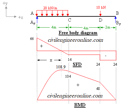
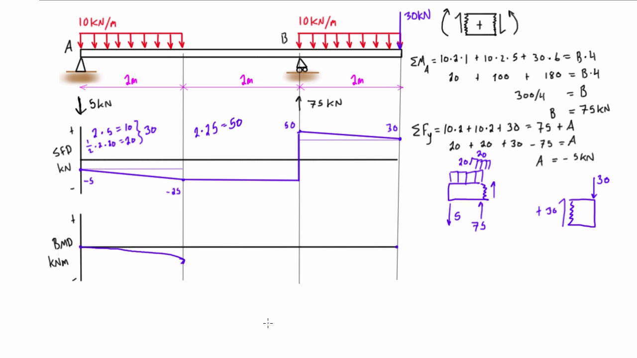
4. A simply supported beam is subjected to a combination of loads as shown in figure. Sketch the shear force and bending moment diagrams and find the position and magnitude of maximum bending moment. Solution: To draw the shear force diagram and bending moment diagram we need R A and R B. Fig. 19.4 Shear force and bending moment
4.4 Area Method for Drawing Shear- Moment Diagrams Useful relationships between the loading, shear force, and bending moment can be derived from the equilibrium equations. These relationships enable us to plot the shear force diagram directly from the load diagram, and then construct the bending moment diagram from the shear force diagram.
3m 266 CHAPTER 4 Shear Forces and Bending Moments Solution 4.3-12 Beam with ... 269 Shear-Force and Bending-Moment Diagrams When solving the problems for ...
4.3 Shear Forces and Bending Moments Consider a cantilever beam with a concentrated load P applied at the end A, at the cross section mn, the shear force and bending moment are found Fy = 0 V = P M = 0 M = P x sign conventions (deformation sign conventions) the shear force tends to rotate the material clockwise is defined as positive
Chapter-4 Bending Moment and Shear Force Diagram S K Mondal's Shear force: At a section a distance x from free end consider the forces to the left, then (V x) = - P (for all values of x) negative in sign i.e. the shear force to the left of the x-section are in downward
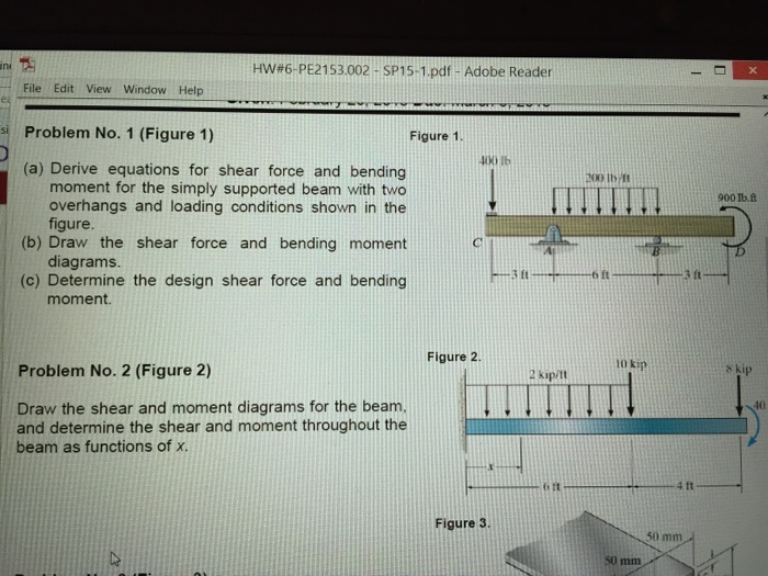
Solved problem no.1 figure 1. (a) derive equations for ...
The two expressions above give the value of the internal shear force and bending moment in the beam, between the distances of the 10 ft. and 20 ft. A useful way to visualize this information is to make Shear Force and Bending Moment Diagrams - which are really the graphs of the shear force and bending moment expressions over the length of the beam.

Shear force and bending moment diagram practice problem #1
bending moment. - Draw the shear force and bending moment diagrams ... EXAMPLE 2 – Solution ... Positive bending moment diagram drawn BELOW the beam. SHEAR ...77 pages
Mechanics of materials chapter 4 shear and moment in beams
PDF_C8_b (Shear Forces and Bending Moments in Beams) Q6: A simply supported beam with a triangularly distributed downward load is shown in Fig. Calculate reaction; draw shear force diagram; find location of V=0; calculate maximum moment, and draw the moment diagram. 6k/ft 9 ft RA = (27k)(9-6)/9= 9k A B F = (0.5x6x9) = 27k x = (2/3)(9) = 6 ft
4.5 practice problems | learn about structures
Module -4. Shear Force and Bending Moment Diagrams. Syllabus. Introduction, Types of beams, loads and reactions, shear forces and bending moments, rate of.12 pages

4.5 practice problems | learn about structures
Calculate the shear force and bending moment for the beam subjected to the loads as shown in the figure, then draw the shear force diagram (SFD) and bending moment diagram (BMD). 2 kN/m 3 m A B EXAMPLE 7

Solved) - determine the reactions and draw the shear and ...
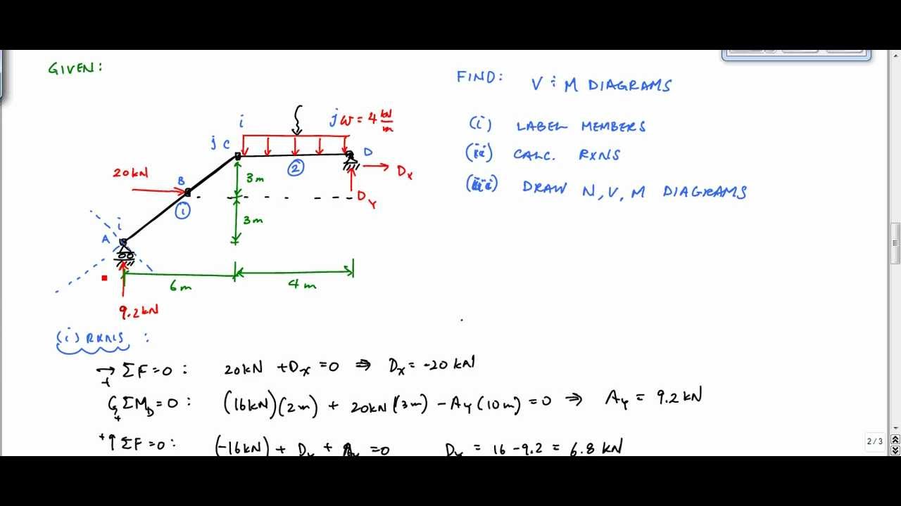
Axial Force, Shear Force and Bending Moment Diagrams for Plane Frames Previous definitions developed for shear forces and bending moments are valid for both beam and frame structures. However, application of these definitions, developed for a horizontal beam, to a frame structure will require some adjustments.
Problem 9.1 two beam segments, ac and cd, are connected ...
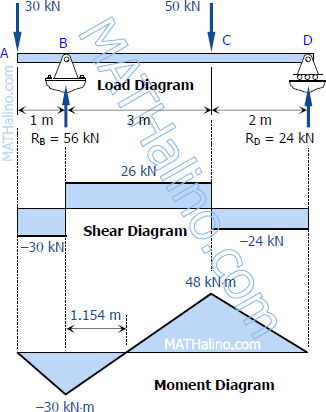
Problem 4.3-3 Determine the shear force V and bending moment M at the midpoint of the beam with overhangs (see figure). Note that one load acts downward and the other upward. Solution 4.3-3 Beam with overhangs 260 CHAPTER 4 Shear Forces and Bending Moments P P b L b P ¢1 2b L ≤ (upward) R A 1 L [P(L b b)] ©M B 0 Free-body diagram(C is the ...
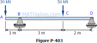
Solution to problem 403 | shear and moment diagrams ...
Shear and Moment Diagrams. As an alternative to splitting a body in half and performing an equilibrium analysis to find the internal forces and moments, we can also use graphical approaches to plot out these internal forces and moments over the length of the body. Where equilibrium analysis is the most straightforward approach to finding the internal forces and moments at one cross section ...
De-12: lesson 19. solved examples based on shear force and ...
Shear Force (SF) and Bending Moment (BM) diagrams. Solution: A Cantilever of length l carries a concentrated load W at its free end. Draw the Shear Force (SF) and Bending Moment (BM) diagrams. Consider the forces to the left of a section at a distance x from the free end. Then F = - W and is constant along the whole cantilever i.e. for all ...
Solved) - draw the shear force and bending moment diagram of ...
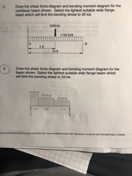
PROBLEM # 1 (25 points) A simply supported beam AH is subject to a constant distributed load q over the section BC, a moment M0 and a concentrated force P at D. The cross section of the beam is shown below. The parameters are following: L=8 ft., q=10 lb/ft, M0=40 lb×ft, P=10 lb, b= 2 in. a) Draw the shear force and bending moment diagrams.

Shear forces and bending moments - pdf free download
w(x) , determine an expression for the shear force as a function of c) Using the relationship clx a) Determine the reactions at supports A and B. b) Write an algebraic expression for the trapezoidal loading shown w x equilibrium. Graphical Methods Shear-Force & Bending-Moment Diagrams 18 ft 2 kip/ft dx function of x (i.e., M(x) x (i.e., v(x)

The internal normal force and shearforce - solution manual ...
3.2 - Shear Force & Bending Moment Diagrams What if we sectioned the beam and exposed internal forces and moments. This exposes the internal Normal Force Shear Force Bending Moment ! What if we performed many section at ifferent values Of x, we will be able to plot the internal forces and bending moments, N(x), V(x), M(x) as a function Of position!
Shear force and bending moment diagram practice problem #4
Check out http://www.engineer4free.com/structural-analysis for more free structural analysis tutorials. The course covers shear force and bending moment diag...

Shear force and bending moment diagrams graphical method ...
0 + (area under the shear diagram from x 0 to x) If there is no externally applied moment M 0 at x 0 = 0, total moment at any section equals the area under the shear diagram up to that section When V passes through zero and is a continuous function of x with dV/dx ≠ 0(i.e., nonzero loading) BM will be a maximum or minimum at this point

Draw shear force and bending moment diagram for cantilever ...
Solved (a) draw shear force and bending moment diagrams for ...

4.5 practice problems | learn about structures

Solved) - draw the shear force and bending moment diagram of ...
De-12: lesson 19. solved examples based on shear force and ...

Diagram geser dan momen - wikipedia
Bending moment & shear force
Solved) - for the beam and loading shown below, (a) evaluate ...
De-12: lesson 19. solved examples based on shear force and ...
Bending moment & shear force

Pdf) shear forces and bending moments | md. shahin alam ...

Bending moment and shear force diagram of a cantilever beam
Cantilever beam sfd bmd / sfd bmd for cantilever beam - youtube
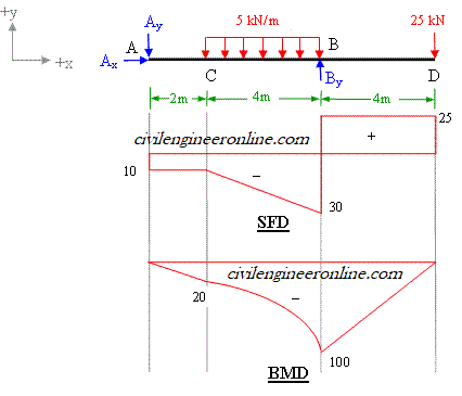
Shear force and bending moment diagram for overhanging beam
Bending moment and shear force calculation - quick and easy
De-12: lesson 19. solved examples based on shear force and ...
Solution to problem 405 | shear and moment diagrams ...
Solution to problem 403 | shear and moment diagrams ...

Shear forces and bending moments
Solved 2. draw the shear force diagram and bending moment ...
Frame analysis example - shear and moment diagram (part 1) - structural analysis
Shear force and bending moment diagram practice problem #7

Gate & ese - numerical problems on sfd(shear force diagram ...
0 Response to "38 shear force and bending moment diagram problems and solutions pdf"
Post a Comment