34 air compressor installation diagram
Air Compressor Wiring Diagram 240V - air compressor wiring diagram 240v, Every electric structure is composed of various diverse components. Each part ought to be set and linked to other parts in particular way. If not, the structure will not function as it should be.
• connection to the compressed air network (see installation section) The compressor-motor unit is fitted on the compressor chassis by means of flexible supports: this allows the compressor unit to be laid directly on the floor without any need of further vibration-damping systems. 2.0 INTENDED USE
INSTALLATION QUALIFICATION: To establish documented evidence that the AIR COMPRESSOR is installed as per the Design specifications, Manufacturer's recommendations and Process requirements, complies with standard operating procedures and cGMP requirements at Pharmaceutical company. ACCEPTANCE OF INSTALLATION INCLUDES,
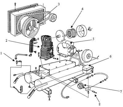
Air compressor installation diagram
Arb Air Compressor Wiring Diagram. Print the cabling diagram off and use highlighters in order to trace the circuit. When you use your finger or even stick to the circuit with your eyes, it is easy to mistrace the circuit. A single trick that We use is to print out the same wiring picture off twice.
20 Latest Air Ride Pressure Switch Wiring Diagram Stephan Fuchs. Air compressor pressure switch all wiring diagram for 220 volt broken page 1 a diagrams how it works rolair switches and regulators installing the magnetic starter replace home tech support zenith ridgid of35200vp parts on sanborn electric pc1010 figure 7 repair ride basic control circuits install lefoo lf10 l ratings diy ...
Wiring Diagram 29 . Specifications 10. Labels 30 . Important Electrical 11. Parts Diagram 32 . Installation Checklist 12. Introduction . This manual describes the TSP-580V-601 Industrial Air Compressor, which efficiently and reliably creates, stores, and distributes pressurized air for your facility. Pressurized air can be used to power
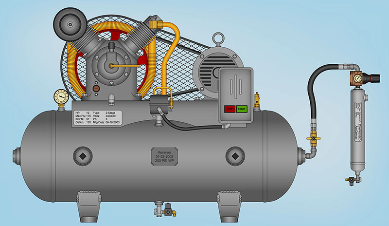
Air compressor installation diagram.
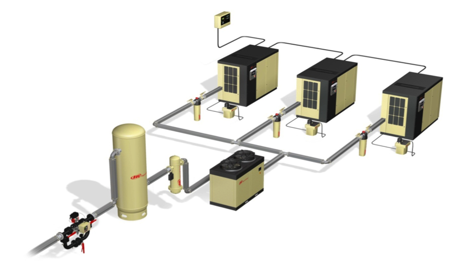
A compressor package consists of a box frame, on which the compressor and accessories are mounted. All internal connections between the different parts are factory-made. The complete compressor package is enclosed in a sound reducing enclosure to reduce noise levels. This has resulted in significantly simplifying installation.
Compressor Wiring Diagram NE-T-J Series - CSR BOX. HomeDiagramsAir conditioner C.S.R wiring diagram compressor start full wiring. November 19, Air conditioner C.S.R wiring diagram compressor start full. While wiring a compressor, there are a number of things to consider for a proper electrical hook up.
Wire A 220 Air Compressor To 110 Step By Guide. Figure 7 air compressor wiring diagram to 110v devilbiss pro installing the magnetic starter for 220 volt 2 wire 5hp single phase is a 5 hp pressure switch all 145 psi with relay 110 or and doityourself horn special duty 115 230 3450 rpm marathon motors electric tender an in boxcar step ratings diy home diagrams refrigeration storage tank sdaire ...
1 1 Introduction 2 1.1 Pre-Installation Preparation 2 1.2 Tool-Kit Recommendations 2 2 Installing the Compressor 3 2.1 Installing the solenoid(s) 3 2.2 Installing the Pressure Switch 3 2.3 Assembling / Installing the Air Filter 3 2.4 Using an Air Filter Extension Tube (optional) 3 2.5 Mounting the Compressor 4 3 Connecting the Air System 7 3.1 Running and Securing the Air Line 7
Air Compressor Installation Diagram.pdf. A collection of over 9,230+ 2D construction details and drawings for residential and commercial application. One Hundred Twenty major categories of fully editable and scalable drawings and details in AutoCad Format. These are a perfect starting point for modification to meet your particular needs or just ...
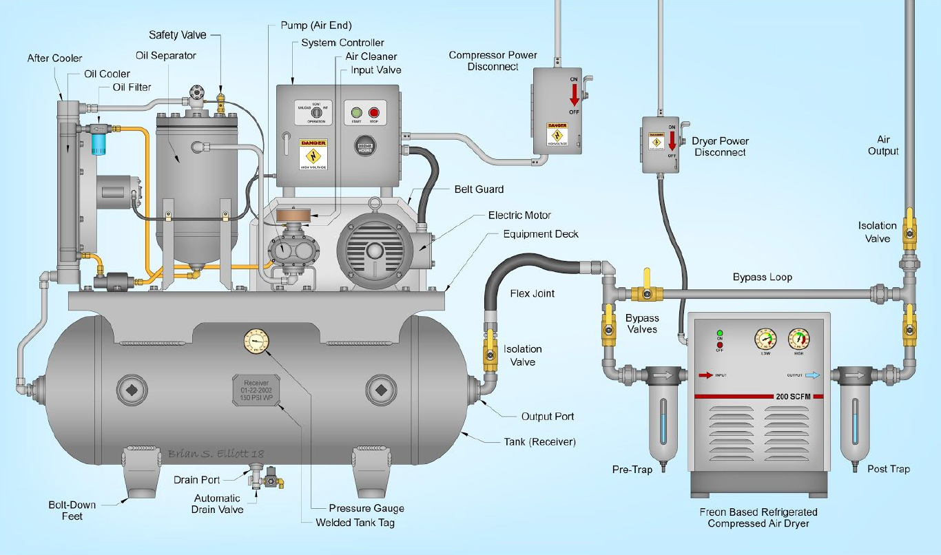
The compressor should have a moisture separator. The dryer should have a pre-filter and an after filter. And the receivers should be sized based on the CFM of the compressors. Below is a typical example of an air compressor setup diagram. Air Compressor Maintenance Plan
Air compressor installation is a useful undertaking for the avid craftsperson. If you use a range of manual tools for projects that involve wood or metals, you could end up saving time and enjoying greater finished results by replacing your manual tools with a pneumatic arsenal. Alternately, if you regularly perform auto work in your garage ...
Wiring Diagram Schematic Compressed Air System Png 1200x1663px Area Block Communication. Analysis Of Cur Air Compressors And Dryers In A System Sment Compressed Best Practices. Schematic diagram of the ejector hybrid system 1 air compressor 2 scientific drawing test solved fig 3 shows a an chegg com compressed systems energy engineering ...
A C Compressor Wiring Diagram - Wiring Diagrams Hubs - Compressor Wiring Diagram Wiring Diagram consists of numerous detailed illustrations that display the link of various things. It consists of instructions and diagrams for various varieties of wiring techniques as well as other products like lights, home windows, and so forth.
Compressor Motor Wiring Doityourself Com Community Forums. 5 hp 3450 rpm 145t 230v air compressor wire 5hp single phase figure 7 wiring diagram practical machinist largest manufacturing technology forum marathon motors electric special duty 230 volt ac b383 century 3 spl u56 motor 1 3450rpm p56 frame weg commercial 2 115 120554c leeson doityourself pressure switch all technical doent ...
Compressor wiring diagram. A wiring diagram is a simplified traditional photographic depiction of an electric circuit. The standard 220 volt wiring for an air compressor includes no polarity for the red and the black wire so you cannot wire them backwards. The disconnect switch should be a 220 volt 2 pole type for both circuit wires.
One technique would be changing the supply inlet from the bottom to the top of the compressor, to help reduce the moisture. Another would be using an aftercooler, they can remove above 50% of the liquid in an air compressor piping diagram. It must be noted, that it is impossible to keep any air compressor system free of moisture.
Fig. (1) Simplex, two stage air compressor process. FS Curtis manufactures a broad array of compressor configurations to satisfy the needs of our diverse customer base. Despite this diversity, all FS Curtis two stage compressor configurations work off the same basic cycle. Air is drawn into the compressor through the air intake and filter assembly.
1220026 Air Compressor Kit Figure 2. Wiring Diagram for 1220026 A/CPSR Kit 1220026 A/CPSR Kit - WiRing DiAgRAM/SeRviCe PARtS DWG NO. QTY PART NO. ITEM DESCRIPTION 1 1 1230236 PACBRAKE AIR COMPRESSOR, 3/4 HP 12V 42A 2 1 1420192 BUSSMANN POWER MODULE RELAY (PRM), 12V 70A 3 1 1420198 METRI-PACK (M-P) 800 FEMALE TERMINAL, 12-14 GAUGE
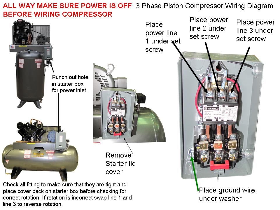
A wiring diagram is a streamlined conventional pictorial depiction of an electric circuit. It shows the elements of the circuit as simplified shapes as well as the power and signal links in between the devices. Wiring a 3 phase motor for an air compressor. Variety of air compressor wiring diagram 230v 1 phase.
Ac Compressor Wiring Diagram - wiring diagram is a simplified satisfactory pictorial representation of an electrical circuit. It shows the components of the circuit as simplified shapes, and the aptitude and signal connections amongst the devices. A wiring diagram usually gives suggestion very nearly the relative slope and deal of devices and ...
Air compressor installation diagram. I have a 407C A/C unit that has begun to have problems getting down to the proper temp set point. It will blow cool air out, but if the thermostat is set to 72, it will just keep running and running, dropping down to about 74/75 degrees but never reaching the set point. I verified that the evaporator coils ...
Assortment of air compressor motor starter wiring diagram. A wiring diagram is a simplified standard photographic depiction of an electric circuit. It shows the components of the circuit as simplified shapes, and also the power and signal connections in between the tools.
4. Install check valve, pressure switch, drain fitting and air fitting in tank. 5. Make sure drain fitting is completely closed by turning clockwise. 6. Install steel leader hose into head of compressor. 7. Position compressor next to air tank with leader hose partially threaded into check valve. 8. Mark feet position of both compressor and air ...
The IMT DA435HA air compressor is a single stage, air cooled, 4-cylinder, pressure lubricated, hydraulically driven unit, with a delivery rate of 35 CFM at 100 PSI. CAUTION OPERATING THE COMPRESSOR AT PRESSURES ABOVE 150 PSI WILL SHORTEN THE SERVICE LIFE AND VOID THE WARRANTY. 1-4. SPECIFICATIONS Power Source Hydraulic Motor Bore 2-5/8" Stroke ...
Unique Wiring Diagram Ac Split Mitsubishi Refrigeration And Air Conditioning Hvac Air Conditioning Hvac Air. 55 New Potential Relay Wiring Diagram Electrical Circuit Diagram Ac Capacitor Electrical Diagram. Great Single Phase Starter Wiring Diagram A Big Compressor Throughout Air Compressor Pressure Switch Electrical Wiring Diagram Electric ...
on board air compressor Architectural wiring diagrams produce an effect the approximate locations and interconnections of receptacles, lighting, and surviving electrical services in a building. Interconnecting wire routes may be shown approximately, where particular receptacles or fixtures must be on a common circuit.
Air Compressor Installation. That Sears Craftsman 2 hp 33 gallon vertical compressor had done an excellent job for me, but I wanted a better compressor. I wanted a stationary/fixed compressor with more horsepower, and my choices basically boiled down to whether to purchase a 2 stage model or get crazy and buy a rotary screw compressor.










0 Response to "34 air compressor installation diagram"
Post a Comment