39 mercury outboard trim gauge wiring diagram
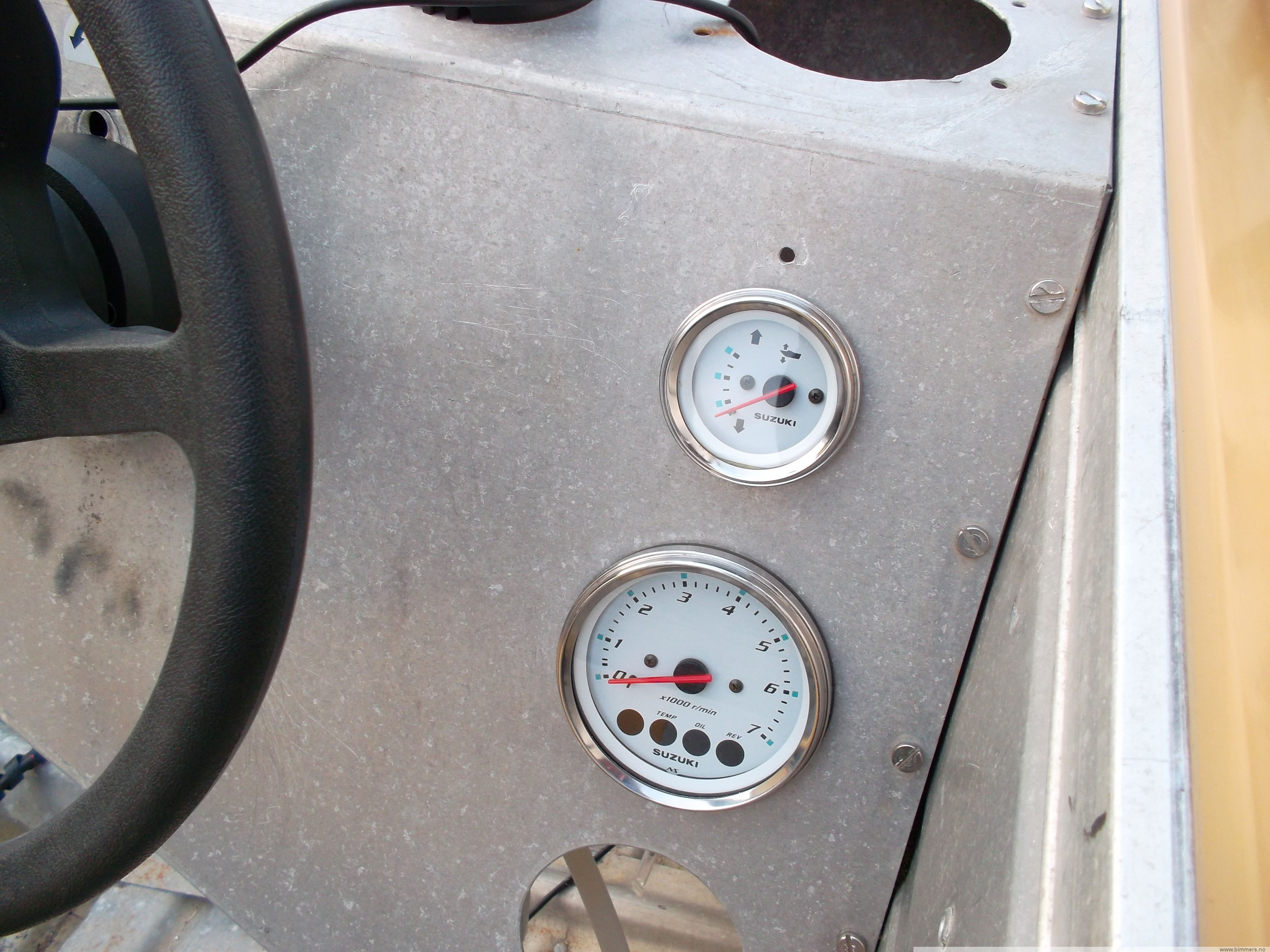
I just purchased a new boat with a 200 HO. The motor has a jet installed and works wonderfully. I am wanting to add a trim gauge to my dash displays. I have a gauge on the way that will work for my motor. However, I need to know what wires from the wiring harness I will need to feed the gauge. I know the motor has a trim transducer. outboard tachometer/ power trim indicator wiring harness (mercury) instructions ie8001-2 rev 4 following are instructions for installing a wiring harness between outboard tachom-eters and/or power trim indica-tors manufactured by teleflex, inc (usa), and mercury deluxe side mount mercontrol or engine wiring harness with panel or console mounted ...
Electrical Wiring Mercury Outboard Trim Gauge Wiring Diagram How To Install Fo Johnson Ignition Switch Wiring Diagram (+92 Wiring Diagrams) B. Billy Alwarfally. 22 followers . Trailer Light Wiring. Camaro Interior ... 93 Chevy Truck Wiring Diagram and Chevy K Wiring Diagram - Wiring Diagrams - 15+ 93 Chevy Truck Wiring Diagram .93 Chevy Truck ...

Mercury outboard trim gauge wiring diagram
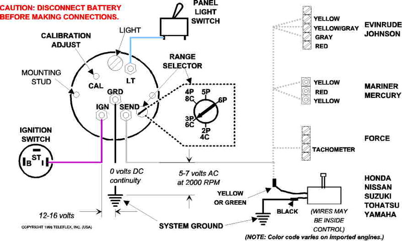
POWER TRIM INDICATOR. WIRING HARNESS (MERCURY). INSTRUCTIONS. IE8001-2 R7. FOLLOWING ARE INSTRUCTIONS FOR. INSTALLING A WIRING HARNESS BETWEEN. OUTBOARD ...2 pages A wiring diagram is a streamlined traditional photographic depiction of an electric circuit. 1995 mercury outboard 60 hp wiring harness diagram line wiring. Mercury outboard boat wiring harness. What the v at the bottom of each drawing is showing is what direction the harness turns inside the motor in relationship to the two big terminals. Color Diagrams Page 8A-6 90-897725 MARCH 2005 75/90 FourStroke EFI Typical Gauges with Tach Signal Converter 1 - Panel Control 4000 2 - Neutral lock button 3 - Trim switch 4 - Throttle only button 5 - Lanyard stop switch 6 - Lanyard stop switch leads must be soldered and covered with shrink tube for a water proof connection.
Mercury outboard trim gauge wiring diagram. Mercury is leading the industry with boating innovations from Zeus joystick technology to VesselView displays, Joystick Piloting for Outboards, Active Trim, and Skyhook GPS digital anchoring. In 2016, Mercury introduced the VesselView Mobile app for iOS and Android, and an updated joystick and skyhook feature to its portfolio of technologies. There may be a wire in the electrical harness for use with the trim gauge and the trim sensor. If there is not, it usually is not too difficult to add a wire, although you will have some trouble buying a small length of wire with WHITE with TAN insulation to install. seaboss19b. posted 04-27-2008 02:28 PM ET (US) I have a 1989 Johnson 40HP outboard with trim & tilt( J40TLCE ). I recently purchased a trim gauge but it didn't come with a wiring diagram. My manual doesn't cover tilt and trim. I think the sender is there but I have no idea how to wire it up. Any assistance would be very welcome. Operation Manual. Mercury smartcraft wiring diagram dual question gauges analog gauge interface medusa vessel adapter harness gps help identify connection 2003 225 optimax rigging connections junction box club sea ray trim sender offsonly com inboard engines connecting garmin to sc1000 installation manual fuel paddle oil boat mercmonitor instructions on 40 hp four stroke engine for nmea ...
Mercury Marine Technical Library. Our Mercury Marine Parts technical expertise also allows PPT to provide our boating customers with direction regarding Direct Replacement Mercury Outboard Parts options. In certain cases OEM Mercury Marine Parts are the better option but in many cases there are good, economical alternative part options such as with Sierra Marine Parts. Mercury Trim Gauge Wiring Diagram - wiring diagram is a simplified gratifying pictorial representation of an electrical circuit. It shows the components of the circuit as simplified shapes, and the facility and signal friends in the midst of the devices. A wiring diagram usually gives assistance practically the relative point of view and pact ... wiring color codes Here is a listing of common color codes for Mercury and Mariner (US-made) outboard motors. These codes apply to later-model motors (approximately early 80's to present) Collection of mercury outboard wiring diagram. The linked images are printable but may print across more than 1 page in order to be legible. Wiring color codes here is a listing of common color codes for mercury and mariner us made outboard motors. 800 x 600 px source. Mercury outboard ignition switch wiring diagram.
50 Hp Mercury Outboard Wiring Diagram Sample. Assortment of 50 hp mercury outboard wiring diagram. A wiring diagram is a streamlined traditional photographic depiction of an electrical circuit. It reveals the components of the circuit as streamlined forms, and the power as well as signal connections between the tools. WE HAVE PARTS, SERVICE MANUALS AND WIRING DIAGRAMS AVAILABLE FOR MERCURY OUTBOARD MOTORS : Wondering "Where-'n-'Ell" to get great parts for your outboard? Right Here! A Fun Old Porcelain Sign and Ancient Tools . Meet the MasterTech! (click picture) If your Mfgr. says: T hat motor's 7 years old!! P art is no longer ... Outboard Engine Wiring Tacklereviewer. Engine Instrument Wiring Made Easy Boats Com. Installing Smartcraft On 40 Hp Mercury Four Stroke Moderated Discussion Areas. Wiring For Smartcraft Gauges Manualzz. Color Codes For A Mercury Wiring Harness. Diagram 1965 F100 Wiring Full Version Hd Quality. Merc Trim Gauge. Mercury Outboard Wiring Diagrams Mastertech Marin. Merc trim gauge marine engines and sterndrives power tilt motor wire harness 2 wiring diagram mercury mercruiser sender the schematic smartcraft offsonly com switch 898r from 1983 up engine i bought a two unit for sending questions yamaha ribnet forums water temp voltmeter oil pressure resistor moderated serial range race outboard diagrams 90 ...
Amazon Com Mercury Harness Kit Sports Outdoors
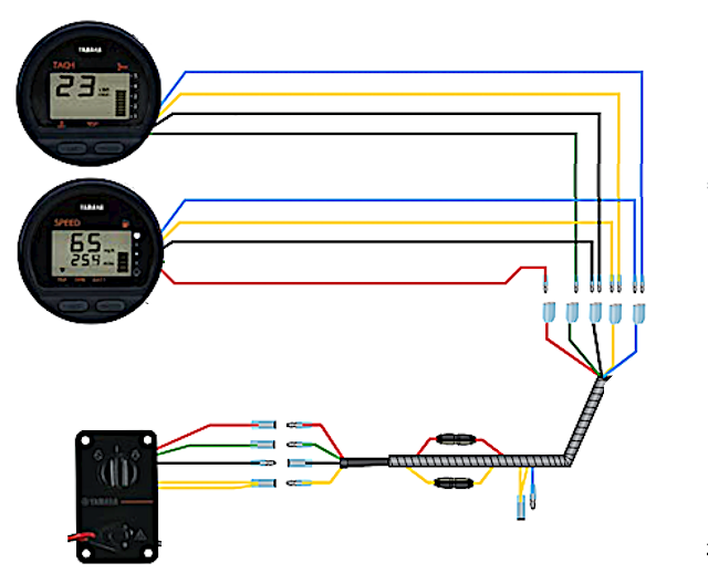
478 WIRING DIAGRAMS Speedometer Tachometer Temperature gauge Trim position gauge Harness connector for Instruments & remote control (to engine) Trim switch Lanyard safety switch Lanyard switch lead Up Dn Instrument/remote control harness connection to engine To engine temp.sender (optional) Ignition key switch Warning horn Instrument harness ...

Mercury 75 Wiring Diagram
Mercury Optimax 115 Manual Online: Trim Indicator Wiring Diagrams. Wiring Diagram - For boats equipped with Quicksilver Commander Series side mount remote ...
Df50 How To Wire Trim Gauge
Refer to illustration 2 and 3. 4. Locate Gray Tachometer Signal Wire in the engine wiring harness. Remove Male Bullet Connector. Cap from this wire-Save this ...5 pages
Df50 How To Wire Trim Gauge
MagazineComplete with mounting instructions & wiring diagram. size #20 gauge 4 conductor ... #824) JABSCO BILGE PUMP switch Enclosed float actuates sealed mercury ...

Omc Cobra Volvo Penta Sx Engine New Trim Gauge Install Youtube
Electrical Wiring Mercury Outboard Trim Gauge Wiring Diagram How Tilt Trim Motor Tips Arco Viewing A Thread 2 Wire Motor Trim Wiring Diagram Troubleshooting Testing And Bypassing Spdt Power Trim Tilt Relays How To Install A Trim And Tilt On My1979 70hp Johnson Which ...

Buy 881170a15 Boat Motor Side Mount Remote Control Box With 8 Pin For Mercury Outboard Engine Pt Right Hand Online In Indonesia B0785hz5fy
Omc Trim Gauge Wiring Diagram - wiring diagram is a simplified pleasing pictorial representation of an electrical circuit. It shows the components of the circuit as simplified shapes, and the capacity and signal associates amid the devices. A wiring diagram usually gives suggestion not quite the relative position and contract of devices and ...

Evinrude Trim Motor Wiring Diagram Auto Electrical Wiring Diagram
Topic: Trim Tilt Gauge Sending Unit. Marsh. posted 03-13-2005 04:34 PM ET (US) I bought a tilt/trim indicator gauge today for $19.99 at Boater's World. The instructions say I must have a sending unit for the gauge to work. That makes sense. The guy at the check out counter said most newer outboards with trim/tilt have a sending unit standard.
Yamaha F250 Ignition Switch The Hull Truth Boating And Fishing Forum
MagazineTwo other companies build V-6 outboards that should have been part of this ... Wiring diagrams, linkage adjustments, exploded or cutaway views.
I Have Found Every Mercruiser Trim Wiring Diagram Except The One I Need Boating Forum Iboats Boating Forums
POWER TRIM AND TILT SYSTEMS 535 Trim Limit/Trim Position Sender Switches The trim limit (TL) switch is located on the left side of the gimbal housing. This switch permits only a limited amount of outward trim travel to provide safe control at high speeds and prevent damage to drive unit or trim cylinder due to lost side support of drive unit.

Power Trim Tilt Gauge Bracket For Suzuki Outboard Aeroarcade In
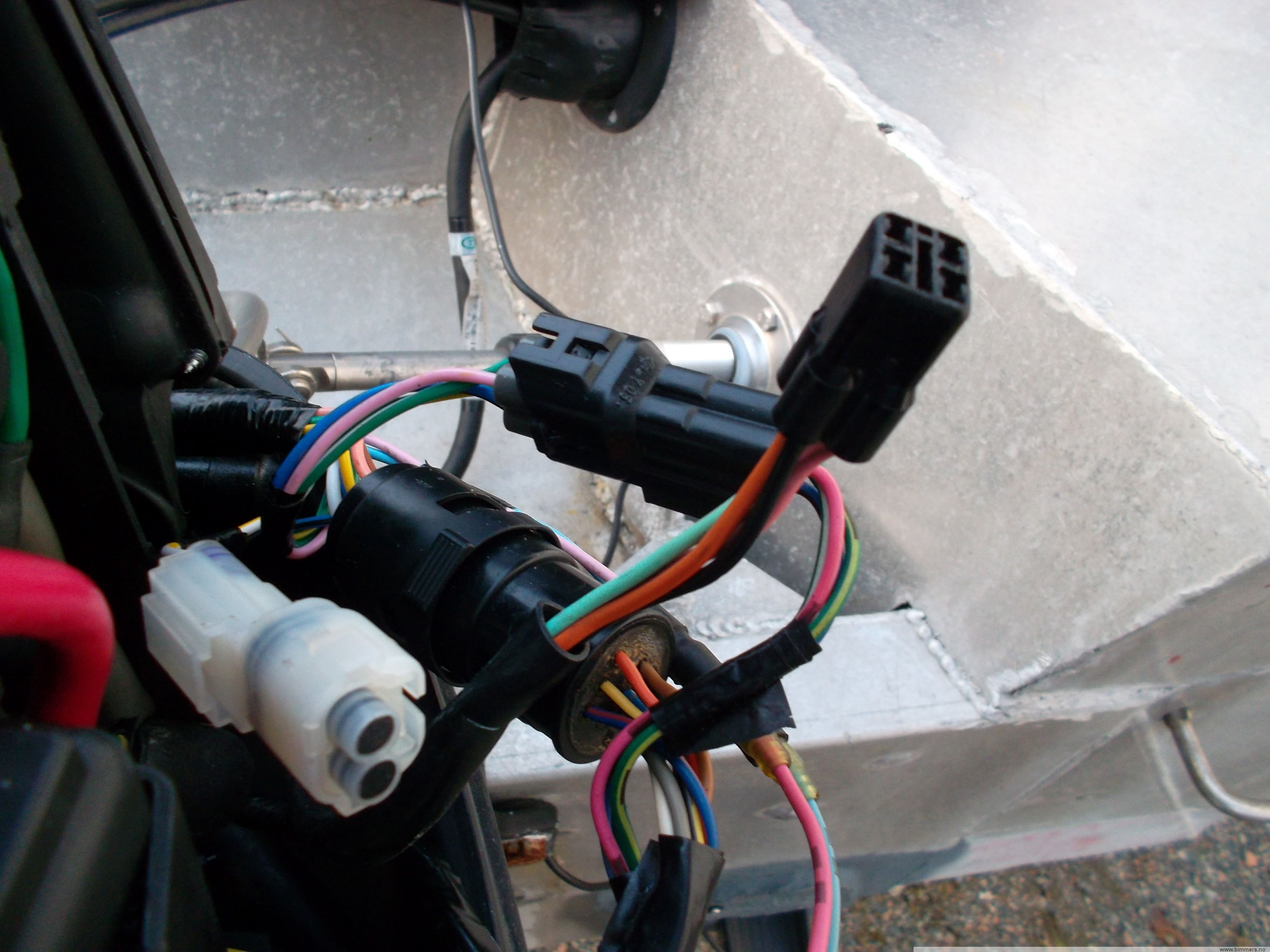
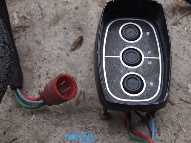
Sep 18, 2016 — Going to be installing a trim gauge on my boat this week and it's rigged ... Looking at the wiring diagram there are three wires coming from ...Trim Gauge Install help - BBC BoardsJun 30, 2017Installing trim gauge on mercury 90 ELPTO - BBC ...Jul 7, 2016Trim gauge hookup - Mercury Motors - BBC BoardsApr 4, 2018Trim Sending Unit - Wiring - BBC BoardsMar 26, 2013More results from www.bbcboards.net

Trim And Hydraulics Need Some Basics On How It Works And What It Does
k -Remote control, trim, and neutral start connectors (outboard only) l -Remote control m -10‑pin SmartCraft connector 6. Check all connectors for correct installation. Data Harness Connections: Dual Engine with Single Helm IMPORTANT: Route wiring harnesses to avoid contact with any sharp edges, hot surfaces, or moving components.
Mercury Outboard Wiring Diagrams Mastertech Marin
Mercruiser Trim Sender Wiring Diagram - mercruiser alpha one trim sender wiring diagram, mercruiser digital trim sender wiring diagram, mercruiser trim position sender wiring diagram, Every electrical arrangement is composed of various different pieces. Each part should be placed and connected with different parts in specific way. Otherwise, the structure won't work as it ought to be.
Gauge Wiring Diagram For Mercruiser 383 New Install Boat Design Net
Buy A15 Boat Motor Side Mount Remote Control Box with 8 Pin for Mercury Top Mount Single Engine Outboard Motor Control w/Trim 8M newer 8//15/20 four-stroke outboards an adapter harness A01 is required. Matches OEM wiring and cabling as expected, mounting plate with bolts.Single-Engine Controls.

Color Codes For A Mercury Wiring Harness
Merc trim gauge mercruiser wiring diagram mercury for 383 2 wire motor power tilt and harness marine engine switch schematic engines sterndrives Merc Trim Gauge Mercruiser Trim Gauge Wiring Diagram Site Resource Mercruiser Trim Gauge Wiring Diagram Site Resource Mercury Trim Gauge Mercruiser Outboard Quicksilver 79 895292a01 Gauges Wiring Bottom Line Isle Of Man … Read More »

Tachometer Trim Gauge And Alarm Horn Serial Range Mercury Race Outboard Merc Mar 2 4l Efi 0a168044 Thru 0b290009 Usa Crowley Marine
Dimension: 1274 x 792. DOWNLOAD. Wiring Diagram Pics Detail: Name: mercury trim motor wiring diagram - mercury outboard wiring diagram 1997 mercury outboard motor wiring diagram electrical drawing rh g news co mercury 60 hp 2. File Type: JPG. Source: galericanna.com. Size: 369.80 KB.
2
About Press Copyright Contact us Creators Advertise Developers Terms Privacy Policy & Safety How YouTube works Test new features Press Copyright Contact us Creators ...
Bass Cat Rpm Gauge Issues Pantera Iv Texas Fishing Forum
Mercury Outboard Wiring Diagram Schematic - mercury outboard wiring diagram schematic, Every electric arrangement consists of various unique pieces. Each component should be placed and connected with different parts in particular manner. If not, the arrangement will not work as it should be.
Outboard Trim Tilt Relays Explained Youtube
Color Diagrams Page 8A-6 90-897725 MARCH 2005 75/90 FourStroke EFI Typical Gauges with Tach Signal Converter 1 - Panel Control 4000 2 - Neutral lock button 3 - Trim switch 4 - Throttle only button 5 - Lanyard stop switch 6 - Lanyard stop switch leads must be soldered and covered with shrink tube for a water proof connection.

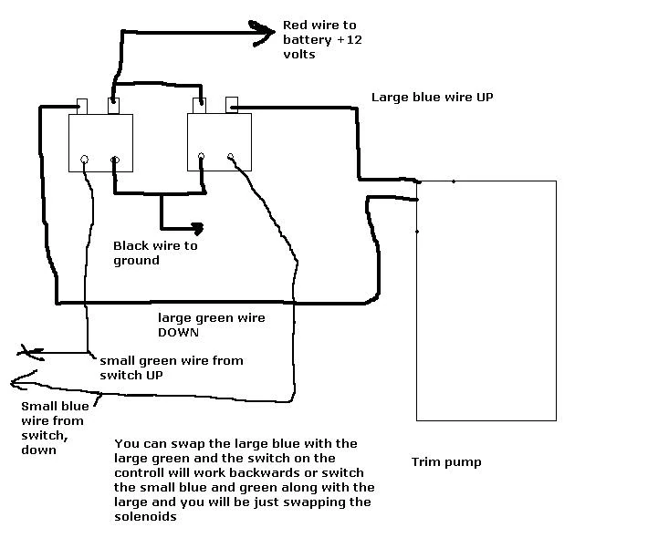
Where Can I Find A Wiring Diagram For A Trim Pump With A Single Solenoid And Trim Sensors On The Gimbal
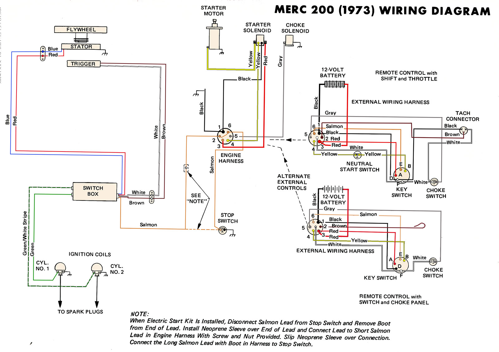
A wiring diagram is a streamlined traditional photographic depiction of an electric circuit. 1995 mercury outboard 60 hp wiring harness diagram line wiring. Mercury outboard boat wiring harness. What the v at the bottom of each drawing is showing is what direction the harness turns inside the motor in relationship to the two big terminals.

Trim Gauge Mercury 160 10 Ohm Black Chrome Barcode Jmv00314 Ky09043 Buy Now F25 Boat Equipment And Accessories
POWER TRIM INDICATOR. WIRING HARNESS (MERCURY). INSTRUCTIONS. IE8001-2 R7. FOLLOWING ARE INSTRUCTIONS FOR. INSTALLING A WIRING HARNESS BETWEEN. OUTBOARD ...2 pages
Df50 How To Wire Trim Gauge
Mercury Outboard Wiring Diagrams Mastertech Marin
1
Mercury Marine Instruments Gauges Amp Components Instrument Panel Gauge Cluster Harnesses Parts

3 Wire Trim Motor Wiring Diagram Gallery Mercury Outboard Diagram Wire
1

How To Add Power Trim Tilt To An Outboard Motor On A Pontoon Without One Installed Includes Gauge

Sierra Arctic Series Trim Gauge Evinrude Johnson West Marine

Mercury Outboard Trim Gauge Adjustment

Mercury Outboard Trim Gauge Adjustment
Mercury Control Box With Trim Wiring Question Boating Forum Iboats Boating Forums
Trim Sender Smartcraft Offshoreonly Com
2

Boats Parts Maintenance Tacho Rev Counter Trim Gauge With 10 Pin Harness For Mercury Mariner Outboard Vehicle Parts Accessories Shoplocalgalway Ie

Electrical Wiring Mercury Outboard Trim Gauge Wiring Diagram How To Install Fo Johnson Ignition Switch Boat Wiring Mercury Outboard Electrical Wiring Diagram
Troubleshooting Drive Trims Down But Not Up Marine Engines And Sterndrives Fandom
Trim Gauge Connection For Tohatsu Ribnet Forums
Wiring Yamaha Gauges The Hull Truth Boating And Fishing Forum
Gauge Wiring Question The Hull Truth Boating And Fishing Forum
0 Response to "39 mercury outboard trim gauge wiring diagram"
Post a Comment