38 pod brake controller wiring diagram
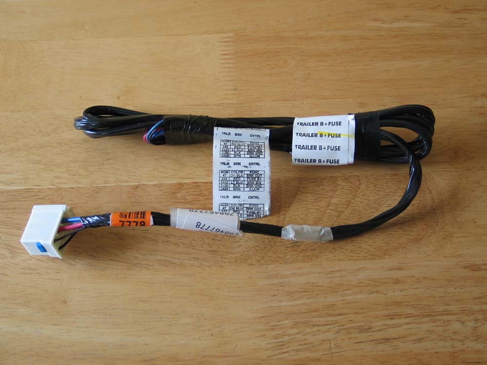
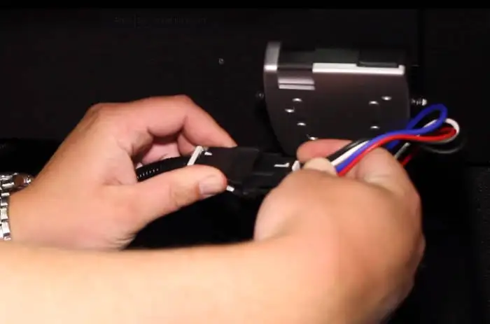
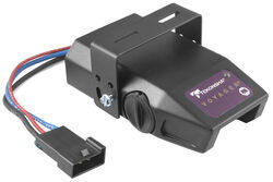
Step 1. Connect the supplied pigtail wiring harness into the electrical connection port on the rear of the pod brake controller. Purchase a wiring harness specific to your vehicle application from your vehicle's manufacturer, and plug that harness into the recommended connection portal. Place the pod controller inside the cab of the vehicle ... Place the pod controller inside the cab of the vehicle near its. Hayman reese electric brake controller wiring diagram wiring diagram is a simplified tolerable pictorial representation of an electrical circuit it shows the components of the circuit as simplified shapes and the capacity and signal contacts between the devices.
Brake Controller. We have a new 177--have taken two trips so far, both successful for most part. Love the R-Dome, though it did get 'airborne' first night when it was not staked well enough. We went through the mountains of Western North Carolina into South Carolina last week and the brakes on the trailer quit working about 150 miles from home.

Pod brake controller wiring diagram
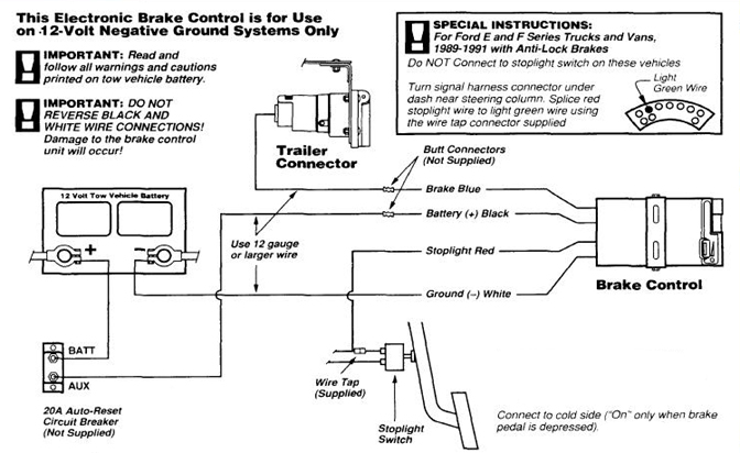
R Pod Trailer Wiring Diagram - People today comprehend that trailer is a vehicle comprised of very complicated mechanisms. This automobile is designed not just to travel 1 location to another but also to carry heavy loads. This guide will be talking r pod trailer wiring diagram.What are the benefits of understanding such understanding? Accu Power Pod Brake Control Pro Series 80550. Hayes brake controller wiring diagram trailer control troubleshooting 80500 accu power pod full reese towpower controllers 7437711 find electronic timed controls installation starting the best and pro series 16 f250 f350 f450 f550 new x4 lot reviews of 2021 14 18 silverado sierra 7 for rvs 550 oem page 3 towing 74 vw alternator 95 09 dodge 83501 ... The brake control must be installed with a 12 volt negative ground system. (To install with a positive ground system use Tekonsha ® P/N 3191.) 2. WARNING Reversing BLACK and WHITE wires or improper wiring will damage or destroy brake control. 3. WARNING Be sure to solidly connect all four wires or brake control will not function properly. 4.
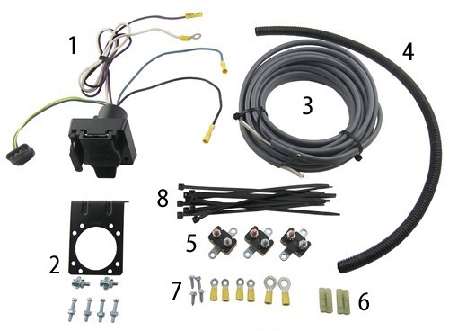
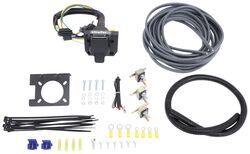
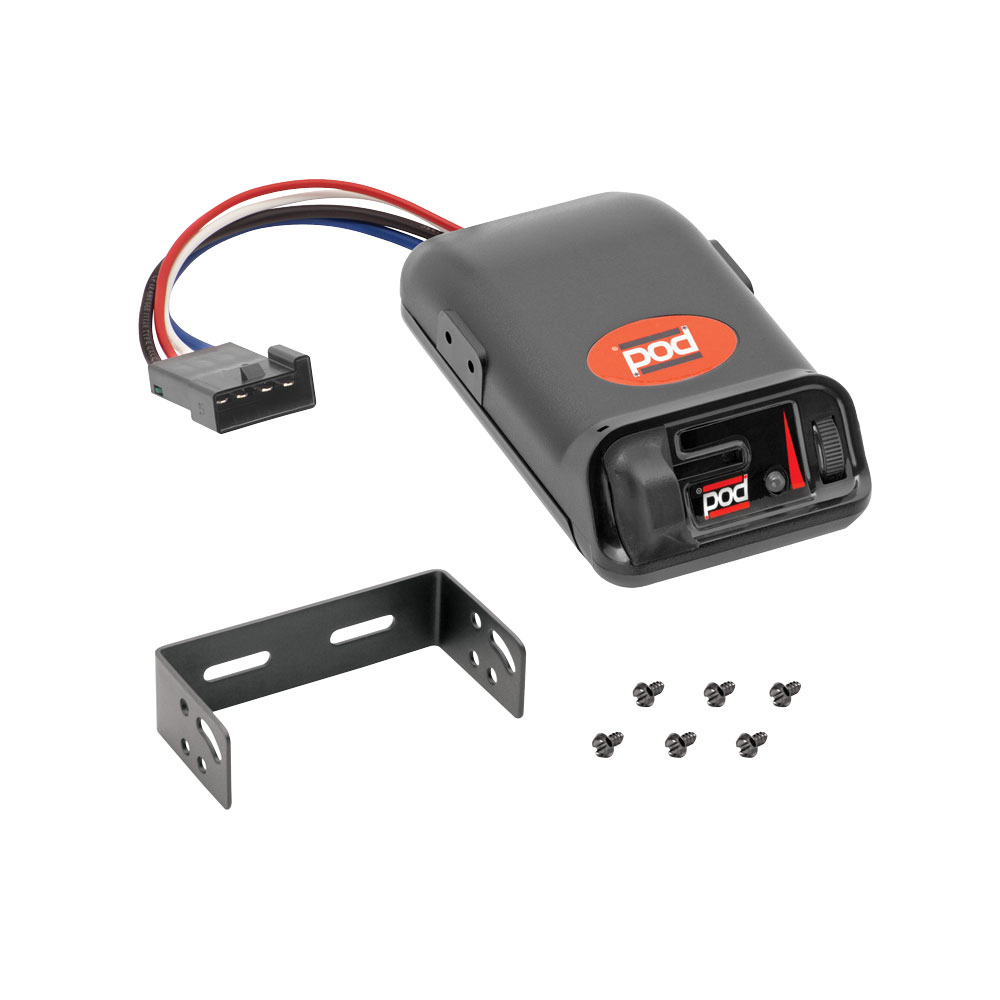
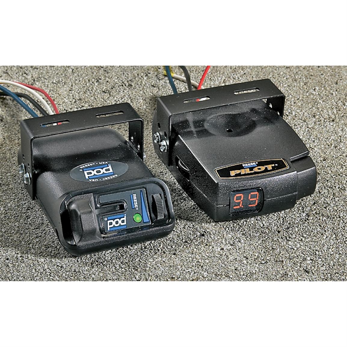
Pod brake controller wiring diagram. POD Brake Control for 1 & 2 Axle Trailers - #80500. Features Include: Solid State Electronics. Power-on LED Light for a positive tow vehicle to trailer connection. Has a manual over-ride control. Very rugged, and has a easy mount chassis. All Mounting Hardware is included. Connect the pigtail-style wiring harness included with the purchase of the Tekonsha brake controller to the back of the in-cab controller unit. Following the wiring diagram included with the controller, run the blue wire through the firewall and to the rear of the vehicle where it will connect to the trailer connector.Brake Controller Wiring ... Pod Point are UK leaders in electric vehicle charging with innovative solutions for homes workplaces and commercial organisations. Pod Brake Controller Wiring Diagram Point R 177 Challenger Radio. Guitar POD unit Amplifier CDMP3 input with 14 dummy plug in the instrument input 2 If your amplifier has an effects loop ie. Untitled. Trailer brake control wiring diagram controller wire functions by hayman reese compact iq how to install your installation controls accu power pod electric brakeman pro series 80550 pilot connection toyota tekonsha primus harness with 30amp starting untitled controllers instructions p3 cheap for 05 18 towpower towing hitch hidden 3016 p redarc tow kit ford guides 05550 page 2 ...
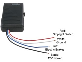
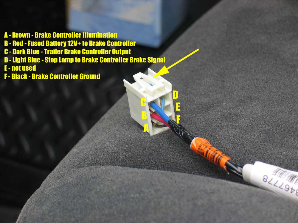
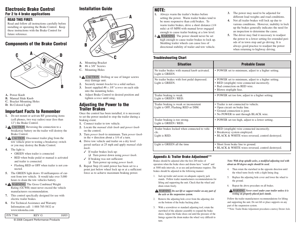
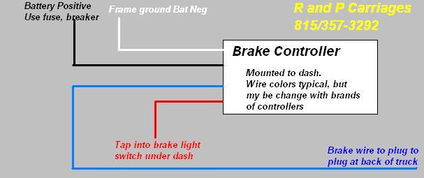
Instructions for Pod® Brake Control READ THIS FIRST: Read and follow all instructions carefully before installing or operating the Brake Control. Keep these instructions with the Brake Control for future reference. D B C A Installation Guide A. Mounting Bracket B. #6 x 3/8" Screws C. Mounting Holes A C B P/N 7760 REV G NOTE: 1. The Reese Pod brake controller should be connected as follows. White - Ground Black - 12 Volt Constant Power Red - Cold Side of the Brake Pedal Switch Blue - Trailer Brake feed to Trailer Brakes If you are correctly wired and you are still experiencing problems, I would start with the following test. Start by disconnecting the blue brake feed ... Pod Electronic Brake Control, for 1 to 2 Axle Trailers . $42.95. Break Away Kits | Brake Control Wiring Harnesses BRAKE CONTROLLER INSTALL KITS: Part # Description. Price . Buy Now: 20505: Wiring Kit for 2 to 4 Brake Control Systems, Includes 25 ft. 12-2 Duplex Wire, 20 Amp Circuit Breaker and Attaching Terminals ... Reese Pod Brake Controller Wiring Diagram. Effectively read a wiring diagram, one provides to find out how the particular components inside the program operate. For example , if a module will be powered up and it also sends out the signal of half the voltage and the technician will not know this, he would think he has a problem, as this ...
Presented by Hayman Reese technical towing expert Gary Gardiner, watch the typical installation process of Hayman Reese Brake Controllers, including end-to-e... Reese Pod Brake Controller Wiring Diagram from images-na.ssl-images-amazon.com Effectively read a wiring diagram, one provides to find out how the components inside the program operate. For example , when a module is usually powered up also it sends out a signal of 50 percent the voltage plus the technician would not know this, he'd think he ... The brake control must be installed with a 12 volt negative ground system. (To install with a positive ground system use Tekonsha ® P/N 3191.) 2. WARNING Reversing BLACK and WHITE wires or improper wiring will damage or destroy brake control. 3. WARNING Be sure to solidly connect all four wires or brake control will not function properly. 4. Travel Trailer wiring, lights and electronic brake control. I need a simple schematic to wire my truck to a travel trailer. I have a 2003 23' Frontier Travel Trailer that needs to be wired to a 1996 Chevy 1500 series extended cab. The electronic brake control is the problem (Reese Towpower Pod #74377), because if it is wired wrong and power is ...
Reese Towpower 7437711 Pod Brake Control Ebay
Electric Brake Controller Wiring Diagram. Wiring Diagram. Auxiliary connection is optional, it may be connected to any 12v to 24v constant power source or left unconnected. Break away systems may be added to the service brake circuit. Elecbrakes is designed to operate 1 to 2 braked axles. Get.

Reese Towpower 7437711 Pod Brake Control Vehicle End For Sale Online Ebay
Hayes brake controller wiring diagram trailer control troubleshooting 80500 accu power pod full reese towpower controllers 7437711 find electronic timed controls installation starting the best and pro series 16 f250 f350 f450 f550 new x4 lot reviews of 2021 14 18 silverado sierra 7 for rvs 550 oem page 3 towing 74 vw alternator 95 09 dodge.

Wire Up Your Tow Pro Elite Wiring Diagrams Redarc Electronics
Installing a brake controller involves disconnecting the vehicle battery, mounting the brake controller onto dash and plugging the unit in with a vehicle-specific wiring harness. If your vehicle is not equipped with a plug-and-play harness, you can also splice in wiring for connecting a brake controller. In this guide, we cover step-by-step how to install a brake controller.

14 20 Ram Pro Master 1500 2500 3500 7 Way Rv Trailer Wiring
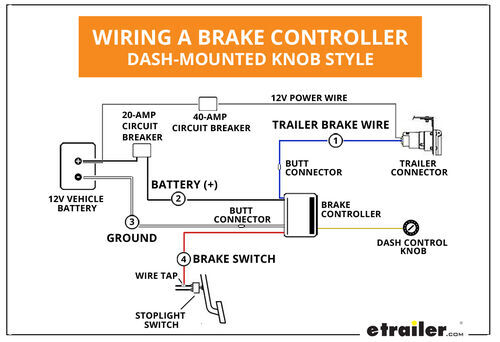
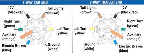
The wiring diagram to the right is a basic brake controller hook up. The wiring harness shown is typical of any electric brake control installation. Some newer vehicles provide their own brake control jumper harness which makes the install a plug and play affair. When you purchase a brake controller and install it on a vehicle without a factory ...
Brake Controller Installation Starting From Scratch Etrailer Com
Wiring diagram for reese brake controller. Quick splice connectors and circuit tester included. The 27l i4 standard in all regular and access cab trucks regardless of drive train not available in the x runner or double cab trucks. Additional wire leads for brake power and accessory are 12 long. Tow ready wiring 30717.

Brake Controller Harness Wiring Nissan Titan Forum
Carlisle Brake Controller Wiring Diagram. The locomotive magazine and railway carriage and wagon review volume 42 1936 key page. When you call please have the part number and a brief description of the. Trailer Wiring Diagram With Electric Brakes Admirable Wiring Diagram. Hydrastar Brake Actuator Electric Hydraulic Brake Actuator Hba16.
Tekonsha Brake Control Wiring Harness Jeep Gladiator Forum Jeepgladiatorforum Com
1. Connect the supplied pigtail wiring harness into the electrical connection port on the rear of the pod brake controller. Purchase a wiring harness specific to your vehicle application from your vehicle's manufacturer, and plug that harness into the recommended connection portal. Reese has always strived to provide the right trailer towing ...

Tekonsha Trailer Brake Controller Install Youtube
@JonG I have a 2020 Dodge durango. I have to hard wire my brake controller in. On my wiring harness for the brake it has 2 12 gauge wires black and blue and 16 gauge red and white. On your wiring diagram it says to use 12 gauge or higher. Should I match the wires according to my wiring harness or use 12 gauge on all?

Reese Towpower 7437711 Pod Trailer Brake Controller Timed 1 To 2 Axles
Reese Pod Brake Controller Wiring Diagram. schematron.org Today on this Chevrolet Silverado were going to install part number The Pod (Power on Demand) trailer brake control is your best choice, Accu- Power Pod Brake Controller, Tekonsha Installation Instructions, CLICK HERE. The REESE Towpower POD trailer brake control is designed for one to ...
How To Install The Tekonsha Powertrac Electronic Brake Controller Etrailer Com
Reese Trailer Brake Controller Wiring Diagram - People understand that trailer is a car comprised of very complicated mechanics. This vehicle is designed not only to travel one place to another but also to carry heavy loads. This guide will be discussing reese trailer brake controller wiring diagram.What are the advantages of knowing such understanding?
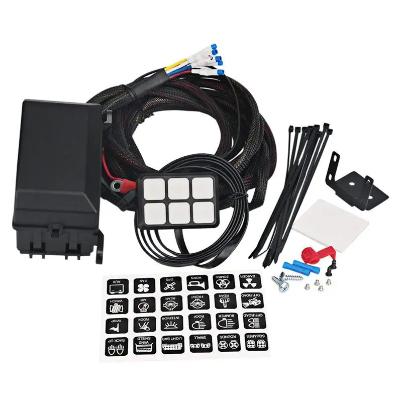
6 Gang Switch Panel Electronic Relay System Circuit Control Box Waterproof Fuse Relay Box Wiring Harness Assemblies For Car Auto Car Switches Relays Aliexpress
Draw-Tite Activator Electronic Brake Control 1-2 Axle Trailers (2-4 Brake Trailers) $85.00 Activator® IV Electronic Brake Control, for 1 to 4 Axle Trailers, Timed Actuated
Trailer Brake Control Wiring Diagram
The brake control must be installed with a 12 volt negative ground system. (To install with a positive ground system use Tekonsha ® P/N 3191.) 2. WARNING Reversing BLACK and WHITE wires or improper wiring will damage or destroy brake control. 3. WARNING Be sure to solidly connect all four wires or brake control will not function properly. 4.
Reese Towpower Trailer Brake Control Pod For 1 To 2 Axles 7437711 At Tractor Supply Co
Accu Power Pod Brake Control Pro Series 80550. Hayes brake controller wiring diagram trailer control troubleshooting 80500 accu power pod full reese towpower controllers 7437711 find electronic timed controls installation starting the best and pro series 16 f250 f350 f450 f550 new x4 lot reviews of 2021 14 18 silverado sierra 7 for rvs 550 oem page 3 towing 74 vw alternator 95 09 dodge 83501 ...
Pro Series Pod Brake Controller Control Module Trailer Brakes
R Pod Trailer Wiring Diagram - People today comprehend that trailer is a vehicle comprised of very complicated mechanisms. This automobile is designed not just to travel 1 location to another but also to carry heavy loads. This guide will be talking r pod trailer wiring diagram.What are the benefits of understanding such understanding?

Pod Brake Control For 1 2 Axle Trailers
Find Reese Pod Electronic Brake Controller 7746 Trailer Brake Tested See Pics In Redlands California United States For Us 27 00

Redarc Ford Ranger Everest Tow Pro Wiring Kit With Aeb
Troubleshooting Brake Controller Installations Etrailer Com
Billavista Com Trailer Brake Controller Tech Article By Billavista

Buy Suzco 6 Pack Trucks Led Rgb Neon Underglow Pod Rock Lights Kit Dual Zone 96leds 2 In 1 Line Sync Music Multicolor Under Lights Waterproof 12v With App Rf Ir For Jeep Offroad Atv Utv Suv Online In Turkey

Trailer Brake Controller Installation How To 5 Easy Steps
Billavista Com Trailer Brake Controller Tech Article By Billavista
Trailer Brake Controller Installation How To 5 Easy Steps
Pod Brake Control For 1 2 Axle Trailers
Towing A Trailer Let S Talk About Brake Controllers Etrailer Com
Reese Pod Electronic Brake Controller 92449 Towing At Sportsman S Guide

Amazon Com Reese Towpower 74377 Pod Brake Control Black Automotive

Trailer Wiring And Brake Control Wiring For Towing Trailers
Pro Series 80500 Pod For 1 And 2 Axle Trailers User Manual 4 Pages
Wiring Diagram Tekonsha Voyager Brake Controller 39510 Etrailer Com
Trailer Brake System Chevy And Gmc Duramax Diesel Forum
Prodigy Wireless Brake Controller Forest River Forums

Control Pod Design Of Ufsckite Research Group S First Prototype Download Scientific Diagram
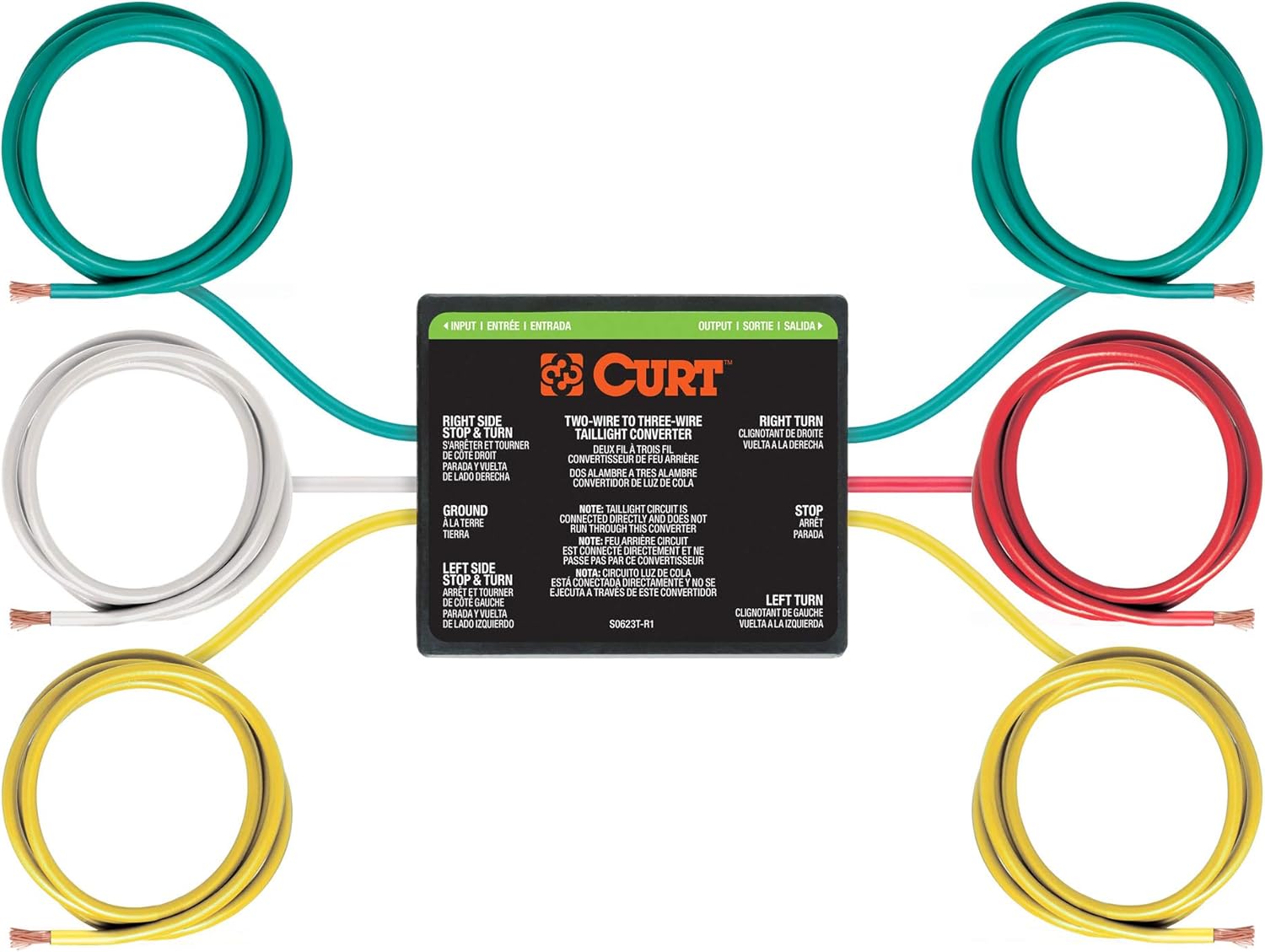
Buy Curt 56196 2 To 3 Wire Splice In Trailer Tail Light Converter For Rv Dinghy Towing Online In Hungary B0046ekphy
Oem Trailer Brake Controller Page 3 Chevy Colorado Gmc Canyon
Trailer Brake Controller Operation

Buy Voswitch Overhead 8 Switch Pod Panel With Control And Source Box Green Backlight Compatible With Jeep Wrangler Jk Jku 2007 2018 Online In Indonesia B079jdvv6g

Amazon Com Reese Towpower 7805011 Brake Control Wiring Harness Automotive
0 Response to "38 pod brake controller wiring diagram"
Post a Comment