35 mercruiser shift interrupter switch wiring diagram
I need a wiring and hydraulic line diagram for a 1976 mercruiser trim pump. I'm not sure if the solenoids and wires from the trim switch are wired correctly. Its a black metal trim pump, with the square base. It doent have the plastic reservoir. I also did a motor swap. Looking for some wiring advise. I have a Mercruicer leg with interrupter switch and a Chevy HEI distributor and am trying to find out how to connect them. I understand the distributor isn't a marine unit but it was all working find before the engine was removed to rebuild and the electrical guy's I got to rewire didn't connect the switch back up.
Carbureted Shift Assist SHIFT CUTOUT WIRING DIAGRAM (Mercruiser & Early O.M.C.) Delco E.S.T. Distributor WIRING DIAGRAM ©2013 Marine Power Holding, 17506 Marine Power Industrial Park, Ponchatoula, LA 70454 marinepowerusa.com MP031022013P3 16 2 AMP INLINE FUSE DISTRIBUTOR COIL SHIFT INTERRUPT SWITCH CONNECT TO +12V POWER SUPPLY

Mercruiser shift interrupter switch wiring diagram
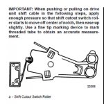
wire. Follow the diagram to insure proper coil voltage. Use of the shift interrupter circuit requires changing from a momentary grounding switch to one that supplies B+ voltage to the distributor. The shift interrupter lead MUST be routed AWAY from ignition wires, to prevent the inductance of voltage into the shift interrupter circuit. Mercruiser Shift Interrupter Switch Wiring Diagram from schematron.org To properly read a cabling diagram, one offers to know how the particular components inside the method operate. For instance , when a module will be powered up and it also sends out the signal of half the voltage and the technician will not know this, he'd think he has an ... The most complete kit on the market. Fast Drying. High Gloss. The models listed below have the Shift Interrupt Switch mounted either on the Transom Plate or on a shift plate assembly attached at the top of the inner transom plate, with the hydraulic reverse lock valve assembly.
Mercruiser shift interrupter switch wiring diagram. Mercruiser Wiring Diagram - mercruiser 140 wiring diagram, mercruiser alternator wiring diagram, mercruiser ignition wiring diagram, Every electric structure consists of various distinct parts. Each component ought to be placed and connected with different parts in particular way. If not, the arrangement will not work as it should be. Mercruiser Shift Interrupter Switch Wiring Diagram from ww2.justanswer.com. Print the wiring diagram off plus use highlighters to trace the signal. When you make use of your finger or perhaps the actual circuit with your eyes, it is easy to mistrace the circuit. 1 trick that We 2 to printing a similar wiring plan off twice. Problems with 90 Mercruiser 4.3 shift interrupter. I had shift issues last fall and adjusted the cable. I notice its still shifting hard and got playing with the interrupter switch. It's not working yet I pulled it and it connects continuity fine with multimeter test. Somethings not connecting somewhere. May 14, 2021 on Omc Cobra 5.0 Wiring Diagram. Omc cobra 5 0 wiring diagram also marine engine diagrams along with mercruiser raw water cooling system as well as mercruiser shift interrupter switch wiring diagram also transom seal as well as omc cobra 3 0 wiring diagrams in addition mercruiser shift interrupter switch wiring diagram together ...
engine-mercruiser 888 (serial no. 3777480 and up), 22b8 (3838888 and up) and 233 shift interrupter switch shift bracket f$-+ terminalblock / ' ' engine groundon k' starter solenoid bracket it i aa i i oil pressure i sender - - - - - - - - 1 oil pnebellrre switch (some yodels) i----- -----' 12.volt battery dlsl electric choke heater-i i ... The latter seems logical because in timing mode, the advance function is disabled by grounding via pin G. However the third diagram shows the wiring in reverse: in timing mode the jumpered wires are R and E, and the 12v source is B. In run mode, B would apparently be the wire to the shift interrupter [which happens to be white/green]. 4e - 2 - wiring diagrams 90-816462 2-695 wiring diagrams 3.0l engine wiring diagram (breaker points ignition) 50726 choke shift interrupt switch alternator optional audio warning water temperature heat switch water temperature sender optional oil pressure switch terminal block engine ground ground stud on engine flywheel housing ground screw on ... Mercruiser Shift Interrupter Switch Wiring Diagram. Print the electrical wiring diagram off in addition to use highlighters in order to trace the routine. When you make use of your finger or perhaps the actual circuit with your eyes, it's easy to mistrace the circuit. One trick that I 2 to print a similar wiring diagram off twice.
The models listed following have the Shift Interrupt Switch mounted either on the Transom Plate or on a shift plate assembly attached at the top of the inner transom plate, with the hydraulic reverse lock valve assembly. An alternate location will have to be selected for mounting the replacement Shift Plate Kit. The new switch will not fit the old mounting plate. Mercruiser sells complete Shift Plate Assemblies to replace the old switch and plate. Shift Interrupt Switch Availability NOTE: 1. For the following models that have the Shift Interrupt Switch mounted to the top of the aluminum rocker cover, an alternate location will have to be selected for ... Has anyone had experience hooking up an HEI distributor with a shift interrupter switch. Have been studying the Mercruiser manual and this is what I have come up with: On some of the wiring diagrams (regular distributor and coil) the negative terminal which serves as the tach signal is also routed to the shift interrupter, I'm assuming that when shifting forward/reverse the switch temporarily ... Installation Manual D7 3l D Tronic Mercury Marine. Mercury outboard wiring diagrams mercruiser 3 0l engine diagram alpha one shift interupt with new tbi interrupter switch and some other electrical engines chaparral boats owners interrupt 18 genuine parts delco ignition system installation manual d7 3l d tronic 4 in my 93 sea ray harness 1998 cable adjustment decks 472 75 90 hp models transom ...
I Recently Installed An After Market Dui Distributor System On My Baja Islander 208 Boat The Engine Is A Modified
enigne cutout switch wiring. I just got a 96 Barchette 182 and am trying to get the engine to shift correctly. The marina guy said its the wire coming from the cutout switch and I should be able to fix no problem. He was wrong. The wire that goes to the distributor is not hooked to anything. There are 2 plugs on the distributor one has wires ...

1999 Mercruiser 5 0l Efi W Throttle Body Erratic Operation After 20 30 Min At Cruise Rpm Northeast U S Chaparral Boats Owners Club
Reconnect the two wires to the shift interrupt switch. Components of Mercruiser 3. The order is also not plausible, unlike wiring schematics. Components of Mercruiser 4. Diagram only reveals where to put component at a spot relative to other components within the circuit. Bypass the shift interrupt switch, as follows A Disconnect wires at shift ...
Mercruiser 260 Shift Cable Neutral Cutoff Switch Adjustment 2 Of 2 Youtube
What About A Wiring Diagram. Mercruiser 3 0l engine wiring diagram marine harness source ignition switch 4 dead boating mercury outboard 5 7 starter question electrical diagrams engines troubleshooting your starting alpha one shift interupt with new tbi 0 litre for a 260 inboard wire in the six g 470 intermittent no spark what about boat supposed to have an module merc kill confusion i need ...
C M Marine Distributing
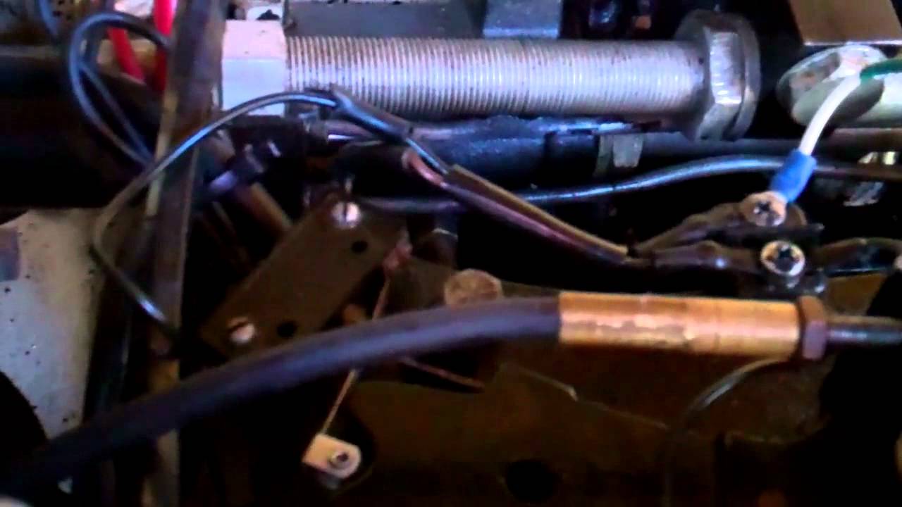
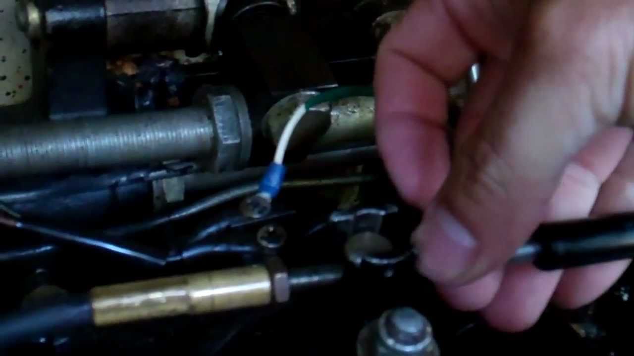
102. May 14, 2010. #14. Re: Shift Interrupt wiring. Hook the green/white wire of the switch to the neg side of the coil and hook the other wire on the switch to a ground. To test it, start the motor and push the switch down and the motor should die.
1999 Mercruiser 5 0l Efi W Throttle Body Erratic Operation After 20 30 Min At Cruise Rpm Northeast U S Chaparral Boats Owners Club
Interrupt Go Here Engine Harness Delco EST Ignition Wiring Diagram Only For Mercruiser I/O The fuel pump is energized by the starter until the motor has oil pressure then the switch provides the power to the pump. The purple from the harness goes to the purple on the coil and also jumps to the oil pressure switch and the shift interrupt switch ...
Jurnal Poltekkesjkt2 Ac Id
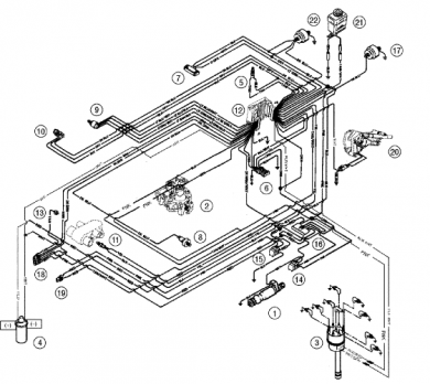
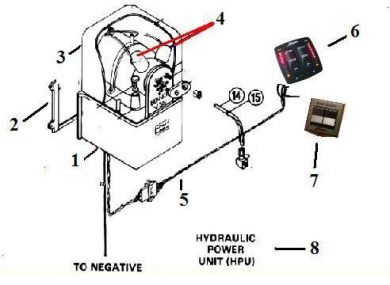
Mercruiser L Engine Wiring Diagrams. A - Ignition Components 1 - Distributor 2 - Ignition Coil 3 - Shift Cutout Switch. B - Starting Charging and Choke Components 1 - Alternator 2 - Electric Choke 3 - Trim Sender. Buy the products and parts you need Buy Parts and Products. or Oildyne hydraulic pump, the trim cylinders, a reverse ...
Mercruiser Not Shifting Dies When It Shifts Sticks Into Gear Adjust Youtube
How to adjust the shift cable and neutral cutoff switch on a mercruiser 260.Part Two: http://www.youtube.com/watch?v=BDxQKic4PBM
Seastarsolutions Com
Mercruiser Shift Interrupter Switch Diagram ~ thanks for visiting our site, this is images about mercruiser shift interrupter switch diagram posted by Maria Rodriquez in Diagram category on Nov 15, You can also find other images like wiring diagram, sensor location, fuel pump location, starter location, control module location, parts diagram ...
C M Marine Distributing
HOW DO YOU WIRE A SHIFT INTERRUPTER SWITCH ON A 5.7 V8 WITH ALFA OUT DRIVE NEED A WIRING DIAGRAM. THANKS ORLANDO - Answered by a verified Marine Mechanic ... I need a wiring and hydraulic line diagram for a 1976 mercruiser trim pump. I'm not sure if the solenoids and wires from the trim switch are wired correctly.

Non Start Mercury 5 0 V8 Rinker Boat Company
The most complete kit on the market. Fast Drying. High Gloss. The models listed below have the Shift Interrupt Switch mounted either on the Transom Plate or on a shift plate assembly attached at the top of the inner transom plate, with the hydraulic reverse lock valve assembly.

I Replaced The 4 3l Engine In My 93 Sea Ray With A New Style Vortec That Had A Delco Voyager Style Ignition System To
Mercruiser Shift Interrupter Switch Wiring Diagram from schematron.org To properly read a cabling diagram, one offers to know how the particular components inside the method operate. For instance , when a module will be powered up and it also sends out the signal of half the voltage and the technician will not know this, he'd think he has an ...

Leviton Dimmer Switch Wiring Diagram Wiring Site Resource
wire. Follow the diagram to insure proper coil voltage. Use of the shift interrupter circuit requires changing from a momentary grounding switch to one that supplies B+ voltage to the distributor. The shift interrupter lead MUST be routed AWAY from ignition wires, to prevent the inductance of voltage into the shift interrupter circuit.

I Have A 3 0l Mercruiser And I Am Trying To Put A Est Ignition System In Place Of A Ddis System

How To How The Shift Interrupt System Works Page 1 Iboats Boating Forums 295363 System Repair And Maintenance Boat
1
Download Brunswick Marine Com
Shift Interrupter Switch Where Is It Boating Forum Iboats Boating Forums

Mercruiser Wiring
Mercruiser 260 Shift Cable Neutral Cutoff Switch Adjustment 1 Of 2 Youtube

Hei Shift Cutout Offshoreonly Com

Genuine Mercury Mercruiser Parts 87 808009t11 Switch Assembly
Marineengines4less Com
Boote Forum De
India Accurascan Com

Cdi 933 4051 Johnson Evinrude Esa Interrupter Switch Harness
Marinepowerusa Com
Alpha One Shift Interupt With New Tbi Conversion The Hull Truth Boating And Fishing Forum
Problems With 90 Mercruiser 4 3 Shift Interrupter Bayliner Owners Club

Mercruiser Tehnicheskie Harakteristiki Sistem Efi Mefi Mpi Alb 3 Manualzz
91 Mercruiser 4 3l Wiring Issues Bayliner Owners Club

Shift Interrupt Switch Youtube

Mercruiser 5 0 No Spark At Plugs

Ignition Switch Troubleshooting Wiring Diagrams Kill Switch Mercury Outboard Boat Wiring
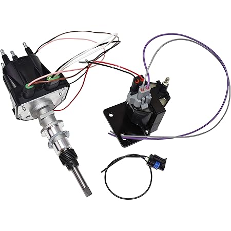
Amazon Com A Team Performance Est Marine Electronic Ignition Distributor And Coil Upgrade Kit 3 0l Delco Est For 4 Cylinder Applications Compatible With Mercruiser Black Cap Automotive
Bpi Ebasicpower Com
0 Response to "35 mercruiser shift interrupter switch wiring diagram"
Post a Comment