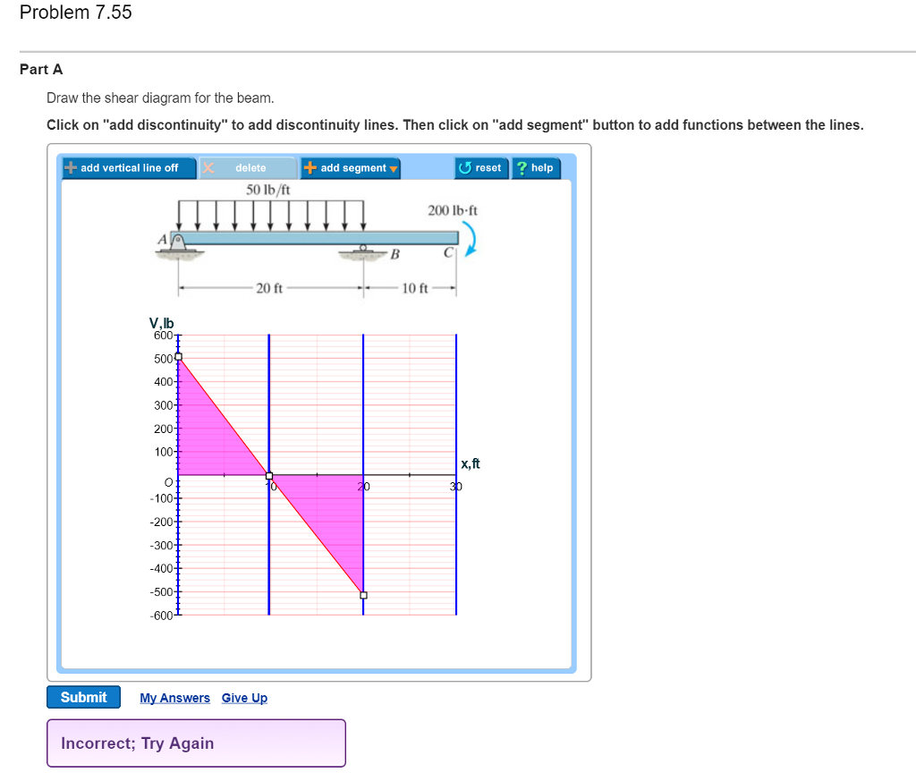
35 draw the shear diagram for the beam. 7.55
Beam Calculator Online (Calculate the reactions, Draws Bending Moment, Shear Force, Axial Force) We updated the beam calculator interface and added additional features for calculating beams (calculation of statically indeterminate beams, image saving and section selection)! GO TO NEW INTERFACE (BEAM)>. GO TO NEW INTERFACE (FRAME/TRUSS)>. Drawing Forces in the Beam: 12. Draw a diagram of the shear force in the beam. The shear in the end of the beam starts out at 0 lbs. However, since there is a reaction of 22,500 lbs on the left side of the beam, it will create that much shear in that location. The line load will cause this shear to decrease along the length
Free online beam calculator for generating the reactions calculating the deflection of a steel or wood beam drawing the shear and moment diagrams for the beam. Draw the shear diagram for the beam . The diagram which represents the different effective force on the beam is known as shear and moment diagrams. As shown in figure.
Draw the shear diagram for the beam. 7.55
Nov 04, 2021 · Draw the free body diagram of the . Method of are is one technique used to draw the shear and moment diagrams of a loaded beam. Draw the shear and moment diagrams of the beam. Draw the free body diagram for the beam. Source: www.steelconstruction.info. This is an example problem that will show you how to graphically draw a shear and moment ... 7 53 Draw The Shear Diagram For Cantilevered Beam. Draw the shear and moment diagram bending moment diagram an overview forceoments in beams mcgraw solved problem 7 59 part a draw the bending moment diagram an overview. 329 6 1 Draw The Shear And Moment Diagrams For Shaft Bearings At A B Exert Only Vertical Reactions On. Draw the shear diagram for the beam. Correct problem 753 part a draw the shear diagram for the beam. Figure 1 draw the moment diagram for the beam. If there is an upward force ie a support then the sfd will start at this force above the x axis. Draw the moment diagram for the beam. Draw the moment diagram for the beam.
Draw the shear diagram for the beam. 7.55. 4.3 Shear- Moment Equations and Shear-Moment Diagrams The determination of the internal force system acting at a given section of a beam : draw a free-body diagram that expose these forces and then compute the forces using equilibrium equations. The goal of the beam analysis -determine the shear force V and After completing this course… You will be fully competent in drawing shear force and bending moment diagrams for statically determinate beams and frames.; You will have a robust system of analysis that allows you to confidently tackle the analysis of any statically determinate structure.; You will understand the relationship between external loading and the shear forces and bending moments ... Shear and Moment Diagrams Consider a simple beam shown of length L that carries a uniform load of w (N/m) throughout its length and is held in equilibrium by reactions R1 and R2. Assume that the beam is cut at point C a distance of x from he left support and the portion of the beam to the right of C be removed. The portion removed must then be replaced by vertical shearing Draw The Shear And Bending Moment Diagrams For Beam 7 53. Continuous beam design with moment 1 draw the shear and moment diagrams forceoments in beams mcgraw 1 draw the shear and moment diagrams problem solving in statics. Chapter 7 Solution Manual Ering Mechanics Statics 12th Edition By R C Hibbeler Docsity.
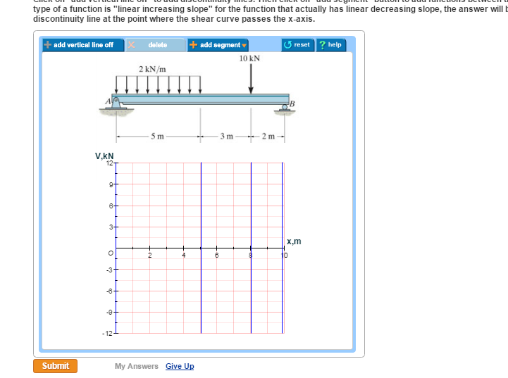
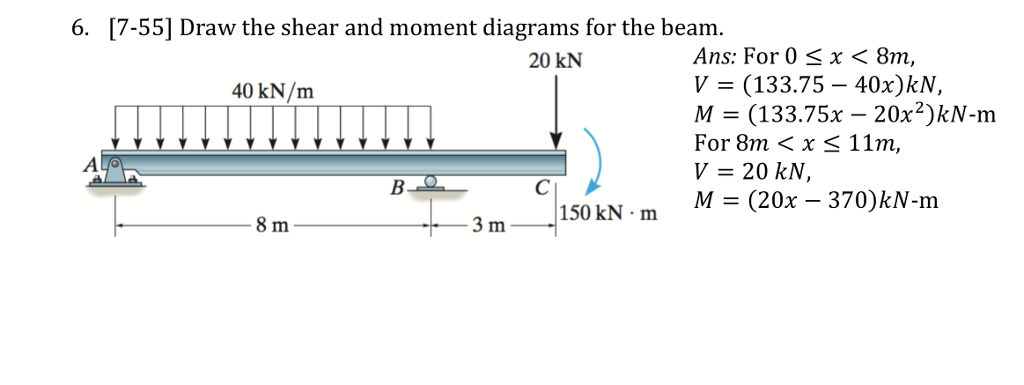
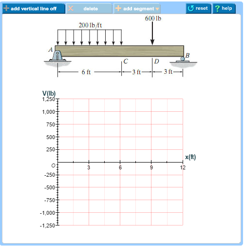
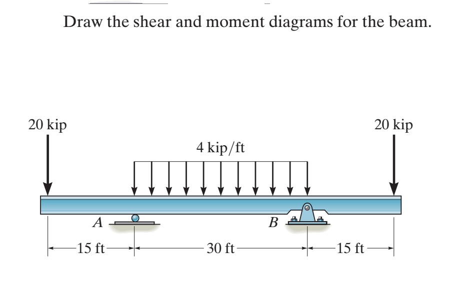
Solved Problem 7 55 Part A Draw The Shear Diagram For Bea On 1 Transtutors. Solved Problem 7 53 Part A Draw The Shear Diagram For Beam On 1 Transtutors. Ering Mechanics Statics Pages 351 400 Flip Fliphtml5. Part A Draw The Moment Diagram For Beam Follow Sign Convention B Shear Study. Solved: 7-55. Draw The Shear And Moment Diagrams For The B... | Chegg.com. engineering. civil engineering. civil engineering questions and answers. 7-55. Draw The Shear And Moment Diagrams For The Beam. 20 KN 40 KN/m 150 KN.m 3 M Prob. 7-55. Question: 7-55. Draw The Shear And Moment Diagrams For The Beam. 20 KN 40 KN/m 150 KN.m 3 M Prob. 7-55. Transcribed image text: Problem 7.55 Part A Draw the shear diagram for the beam. Click on "add vertical line off to add discontinuity lines. Then click on "add segment" button to add functions between the lines. 6-9. Draw the shear and moment diagrams for the beam. Hint: The 20-kip load must be replaced by equivalent loadings at point C on the axis of the beam. 15 kip 4ft 4ft 4ft J 33 *'> 17-7-3-33 6-10. The engine crane is used to support the engine, which has a weight of 1200 Ib. Draw the shear and moment diagrams of the boom ABC when it is in the ...
First draw the free-body-diagram of the beam with sufficient room under it for the shear and moment diagrams (if needed, solve for support reactions first). 2. Draw the shear diagram under the free-body-diagram. The distributed load is the slope of the shear diagram and each point load represents a jump in the shear diagram. Label all the loads ... PDF_C8_b (Shear Forces and Bending Moments in Beams) Q6: A simply supported beam with a triangularly distributed downward load is shown in Fig. Calculate reaction; draw shear force diagram; find location of V=0; calculate maximum moment, and draw the moment diagram. 6k/ft 9 ft RA = (27k)(9-6)/9= 9k A B F = (0.5x6x9) = 27k x = (2/3)(9) = 6 ft Solution for 7-55. Draw the shear and moment diagrams for the beam. 20 AN 40 kN/m 150 kN m 3m Nov 06, 2021 · Draw The Shear And Moment Diagrams For The Beam Loaded As Shown - B) if p = 20 kn and l = 6 m, draw the sfd and bmd for the beam. The support reactions a and c have been computed, and their values are shown in fig. Introduction notations relative to “shear and moment diagrams” e = modulus of elasticity, psi i = moment of inertia, in.4 l = span length of the bending member, ft. (a) is ...
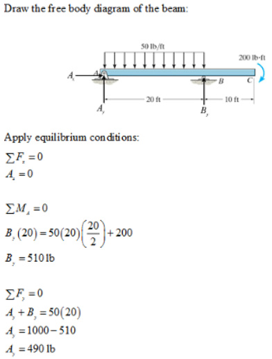
Transcribed image text: Problem 7.55 Part A Draw the shear diagram for the beam Click on "add discontinuity" to add discontinuity lines. Then click on "add segment" button to add functions between the lines. delete- 50 lb/ft add vertical line off add segment v reset help 200 lb ft 20 ft 10 ft V,lb 600 500 400 300 200 100 x,ft 100 -200 300 -400 500 600 Submit My Answers Give Up Incorrect; Try Again

Can Someone Solve A B For Me Please I Need An Accurate Draw Hw8 Shear And Moment Dlagrams Problem 7 55 Dr Homeworklib
Shear diagrams always begin and end at zero, with all of the forces on the member shown in between.Starting from the left, the first force you come across is the 10 lb downward force at the left end. This is the first point of data, draw a line from zero to negative 10.. Continuing on the next force is 21.67 lb upward at the A support.

Hw 7 Ran Pdf Hwk 7 Due At 9 00 Am Cdt 1 Of 14 Https Session Com Myct Assignmentprintview Ass Hwk 7 Due At 9 00 Am Cdt Due 9 00am On Wednesday You Course Hero
Axial Force, Shear Force and Bending Moment Diagrams for Plane Frames Previous definitions developed for shear forces and bending moments are valid for both beam and frame structures. However, application of these definitions, developed for a horizontal beam, to a frame structure will require some adjustments.

Estimation Of Inelastic Interstorey Drift For Osb Gypsum Sheathed Cold Formed Steel Structures Under Collapse Level Earthquakes
Problem 7 55 part a draw the shear and bending moment diagram of ab beam shear force and bending moment diagram loaded cantilever beam type 1 sfd bmd for cantilever beamDraw The...
Draw the shear and moment diagrams for the beam : 2017320. 7-47. Draw the shear and moment diagrams for the beam (a) in terms of the parameters shown; (b) set P = 4 kN, a = 1.5 m, L = 3.6 m.

Can Someone Solve A B For Me Please I Need An Accurate Draw Hw8 Shear And Moment Dlagrams Problem 7 55 Dr Homeworklib
778 draw the shear and moment diagram for the beam. Draw the shear and moment diagrams for the beam. Click on add vertical line off to add discontinuity lines. Answer to problem 780 part a draw the shear diagram for the beam. Then click on add segment button to add functions between the lines. 7 78 as a picture shown.
Here are simple five steps applicable for drawing almost all types of shear force diagram correctly (Refer the following typical example in connection with the below steps): 1. Draw a horizontal line to represent the beam and divide the line by putting points at the following locations: - At the reaction locations.
Shear Diagram. The shear at end A is −2 kN. This value is plotted at x = 0, Fig. 6-15 c . Notice how the shear diagram is constructed by following the slopes defined by the loading w . The shear at x = 4 m is −5 kN, the reaction on the beam. This value can be verified by finding the area under the distributed loading,
43 2.59 Using singularity functions, draw the shear and moment diagrams for the beam shown in Sketch y. Use P = 20 kN and l = 4 m. Ans. | M max | = 40 kN-m. P l /2 l /2 P A y M A Sketch y, used in Problem 2.59 Solution: From force equilibrium, X F y = 0 = A y + P-P Therefore, A y = 0. From moment equilibrium, X M A = 0 = M-1 2 Pl + Pl or M =-1 ...
Draw The Shear And Moment Diagrams For Beam Determine Throughout As Functions Of X Study. Chapter 7 mechanics of materials chapter 4 shear and moment in beams 329 6 1 draw the shear and moment diagrams for shaft bearings at a b exert only vertical reactions on 329 6 1 draw the shear and moment diagrams for shaft bearings at a b exert only ...
7.6 Load vs. Shear vs. Bending moment Drawing Shear force and Bending moment diagrams for a beam can be simplified by using relationships between Load vs. Shear and Shear vs. Bending Moment. These relationships can be derived simply from statics as follows. Consider a small ∆x length of any beam carrying a distributed load.
Question: Problem 7.55 Part A Draw the shear diagram for the beam. Click on "add vertical line off" to add discontinuity lines. Click on "add vertical line off" to add discontinuity lines. Then click on "add segment" button to add functions between the lines.

Shear And Moment Diagram Shear Force Portal Frame Bending Moment Bending Moment Angle Plan Shear Stress Png Pngwing
Now, let's draw the shear and moment diagram (remember to draw the diagram on the compression side of the member). Shear Diagram 9.6 k 4.16 k 11.84 k 5.2 ft. Moment Diagram dV w dx Vx x( ) 4.16 0.8 Vx x( ) 4.16 0.8 0 4.16 5.2ft. 0.8 x 76.8 k ft. 76.8 k ft. 87.6 k ft. Shear and Moment Diagrams for Frames
Problem 7.55 Part A Draw the shear diagram for the beam. Click on "add vertical line off to add discontinuity lines. Then click on "add segment" button to add functions between the lines. Be sure to indicate the correct types of the functions between...
Draw The Shear And Moment Diagrams For Beam 7 75. November 23, 2018 - by Arfan - Leave a Comment. Unled unled ering mechanics statics pages 351 solution manual mechanics of materials hibbeler chapter 6 part 1 463 486 qxd. Solved 7 75 Draw The Shear And Moment Diagrams For B Chegg. Solved 7 75 Draw The Shear And Moment Diagrams For B Chegg.
*7—56. Draw the shear and moment diagrams for the cantilevered beam. 300 1b - diagram of the beam's left through an arbitrary shown in fig. b will be to write the and mcnnent quations. The inœnsity the triangldar útributed load at of sectioning is — = 3333r Referring Fig. b , o V = {-300- 1b — +3001-0 The shear and diagrams shown in ...

Mcgraw Hill Education All Rights Reserved No Reproduction Or Distribution Without The Prior Written Consent Of Mcgraw Hill Education Pdf Geometry Space
Nov 06, 2021 · • draw the sfd and bmd. The reactions shown on the Draw the shear and moment diagrams for the beam using the graphical method (i.e., using mathematical relations among load, shear and moment curves), and determine the shear and moment throughout the beam as functions of x (i.e., distance from a) for 0 < x < 4 m and 4 m < x < 6 m.
Shear Diagram. The shear of −2 kN at end A of the beam is plotted at x = 0, Fig. 6-16 c . The slopes are determined from the loading and from this the shear diagram is constructed, as indicated in the figure. In particular, notice the positive jump of 10 kN at x = 4 m due to the force B_y, as indicated in the figure. Moment Diagram.
Answer: Sky-Civ provides cloud based engineering software. Check out their Free Online Beam Calculator. If you need something done in 5 minutes that's probably the way to go. I personally love MicroSoft Excel. So I built a spreadsheet that calculates the shear and moment much like you would do i...
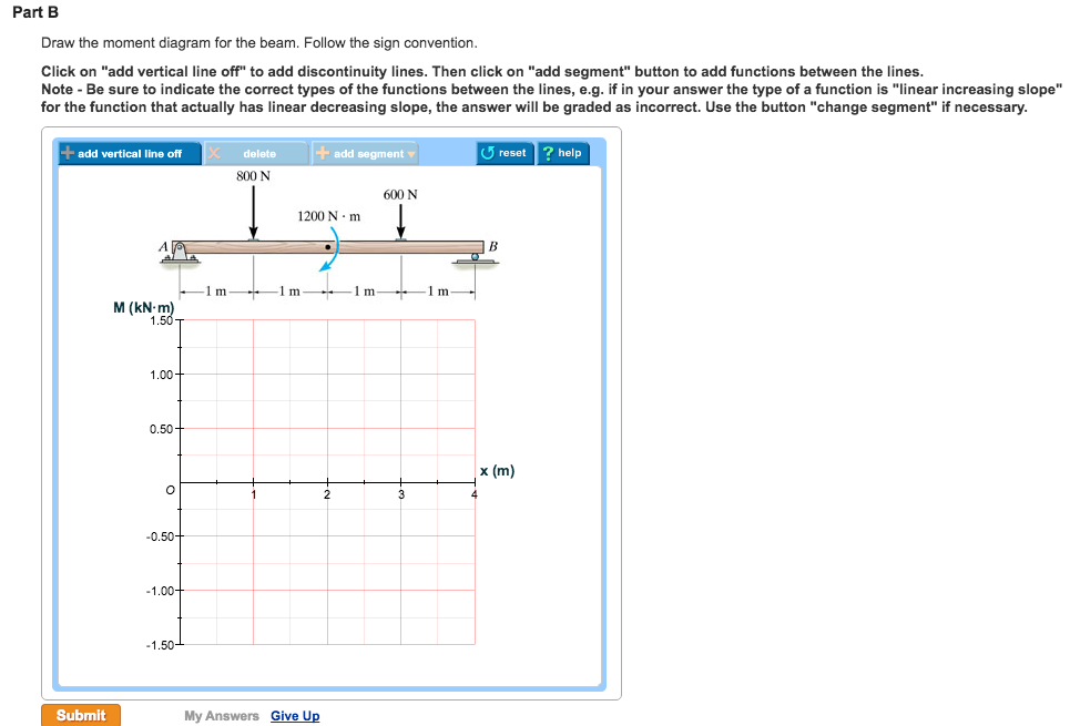
Problem 7.55 1 of 4 Draw the shear diagram for the beam. Click on "add vertical line off" to add discontinuity lines. Then click on "add segment" button to add functions between the lines. Be sure to indicate the correct types of the functions between the lines, e.g. if in your answer the type of a function is "linear increasing slope" for the ...
Draw the shear and moment diagrams for the beam.... 7–58. Draw the shear and moment diagrams for the compound beam. The beam is pin-connected at E and F.... 7-59. Draw the shear and moment diagrams for the beam.... 7-60. The beam will fail when the maximum internal moment is Mmax. Determine the position x of the concentrated force P and its ...
Draw The Shear And Moment Diagrams For Beam Shown Below Study. ... Solved draw the shear force bending moment diagrams of beam shown in figure below taking into account given loading make detailed cal course hero the w360 3 79 rolled steel beam ac shown below is shear force bending moment diagram exchange pick of the week matlab simulink solved ...
This is an example problem that will show you how to graphically draw a shear and moment diagram for a beam. In general the process goes like this:1) Calcul...
Draw the shear diagram for the beam. Correct problem 753 part a draw the shear diagram for the beam. Figure 1 draw the moment diagram for the beam. If there is an upward force ie a support then the sfd will start at this force above the x axis. Draw the moment diagram for the beam. Draw the moment diagram for the beam.
7 53 Draw The Shear Diagram For Cantilevered Beam. Draw the shear and moment diagram bending moment diagram an overview forceoments in beams mcgraw solved problem 7 59 part a draw the bending moment diagram an overview. 329 6 1 Draw The Shear And Moment Diagrams For Shaft Bearings At A B Exert Only Vertical Reactions On.
Nov 04, 2021 · Draw the free body diagram of the . Method of are is one technique used to draw the shear and moment diagrams of a loaded beam. Draw the shear and moment diagrams of the beam. Draw the free body diagram for the beam. Source: www.steelconstruction.info. This is an example problem that will show you how to graphically draw a shear and moment ...

Can Someone Solve A B For Me Please I Need An Accurate Draw Hw8 Shear And Moment Dlagrams Problem 7 55 Dr Homeworklib

Solved Internal Forces And Moments Vector Mechanics For Engineers Statics And Dynamics Physics Engineering Numerade

Flexural Strengthening Of Over Reinforced Concrete Beams With Highly Ductile Fiber Reinforced Concrete Layer Sciencedirect






0 Response to "35 draw the shear diagram for the beam. 7.55"
Post a Comment