34 what is a logic diagram
logic diagramnoun. A diagram in the field of logic. · logic diagramnoun. Any non-spatial, abstract diagram. · logic diagramnoun. Any schematic display of the ... Teach logic gates + digital circuits effectively — with Logicly. Design circuits quickly and easily with a modern and intuitive user interface with drag-and-drop, copy/paste, zoom & more. Take control of debugging by pausing the simulation and watching the signal propagate as you advance step-by-step. Don't worry about multiple platforms on student computers. Install on both Windows and ...
What is a logic diagram
Logic diagrams have several applications in investigations, and are most often developed in an iterative fashion. As shown in the event tree logic diagram in Figure 31.4, in the early stages of an investigation they can be used to illustrate credibly possible reasons, conditions, and events to assist in determining the cause scenario.As shown in Figure 31.5, they can point the investigators to ... Q-Logic Technical Manual www.prideservice.com 7 I. OVERVIEW Q-LOGIC MODULES The basic system is a power module and a hand control. For adjusting seat position, an AAM module is added. For users who require specialized input devices, several options are available. This is a true plug-and-play system, and modules are It uses logic symbols to show the main concept of the circuit. Detailed diagrams take the basic information and add specifics or non-logic data. This data may ...
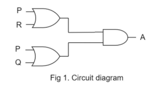
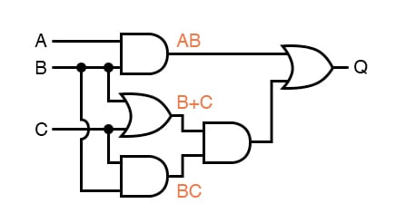
What is a logic diagram. The use of logic symbology results in a diagram that allows the user to determine the operation of a given component or system as the various input signals change. To read and interpret logic diagrams, the reader must understand what each of the specialized symbols represent. This article discusses the common symbols used on logic diagrams. Download the Notes TOPIC 1: Logic Representation There are three common ways in which to represent logic. 1. Truth Tables 2. Logic Circuit Diagram 3. Boolean Expression We will discuss each herein and demonstrate ways to convert between them. TOPIC 2: Truth Tables A truth table is a chart of 1s and 0s arranged to… A logic gate is an idealized model of computation or physical electronic device implementing a Boolean function, a logical operation performed on one or ...INPUT: OUTPUT The logic diagram consists of gates and symbols that can directly replace an expression in Boolean arithmetic. A logic gate is a device that can perform one or all of the Boolean logic operations AND, NAND, NOR, NOT, OR, XNOR, and XOR. All types of logic gate, except NOT, accept two binary digits as input, and produce one binary digit as output.
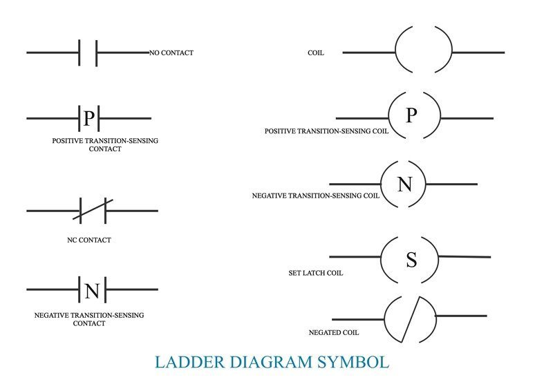
The logic diagram was introduc€ld in 17611 and was, from the time of Hamiiton to the publishing of thE~ Principia Mathematica, a center-of controversy among logicians. Some of the major logical problems of our time are crystallized and clarified, tho~gh not solved, in these diagrams. '2 ... 28.06.2015 · Since ladder logic is a graphical programming language, the PLC programs written in ladder logic are a combination of ladder logic symbols. All the symbols can be found in the standard defining ladder diagram programming: IEC 61131-3. But, those standards are quite expensive if you are just looking for the symbols used in ladder diagrams. 04.09.2017 · Ladder logic (also known as ladder diagram or LD) is a programming language used to program a PLC (Programmable Logic Controller). It is a graphical PLC programming language which expresses logic operations with symbolic notation. Ladder logic is made out of rungs of logic, forming what looks like a ladder – hence the name ‘Ladder Logic’. 13.07.2019 · Ladder Diagrams (LD) (i.e. Ladder Logic) Function Block Diagram (FBD) Sequential Function Chart (SFC) Although all of these PLC programming languages can be used to program a PLC, graphical languages (like ladder logic) are typically preferred to textual languages (like structured text programming). Ladder Logic. Ladder logic is the simplest form of PLC programming. It is also known …
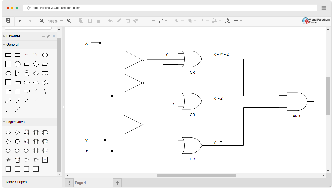
The logic gate software has all the logic symbols you need to design any kind of logic model. No matter you want a logic diagram tool for teaching, or a logic circuit software for engineering purposes, our online logic diagram creator just works perfectly. Besides the logic diagram tool, we've put together some logic diagram templates to help ... PLC logic is a digital computer used to automate electromechanical processes. The Star delta diagram is a diagram for a simple circuit that has the capabilities of starting a high horse power motor. 02.05.2020 · Description: Decoder-In this tutorial, you learn about the Decoder which is one of the most important topics in digital electronics.In this article we will talk about the Decoder itself, we will have a look at the 3 to 8 decoder, 3 to 8 line decoder designing steps, a technique to simplify the Boolean function, and in the end, we will draw a logic diagram of the 3 to 8 decoder. Ladder logic was originally a written method to document the design and construction of relay racks as used in manufacturing and process control. Each device in the relay rack would be represented by a symbol on the ladder diagram with connections between those devices shown. In addition, other items external to the relay rack such as pumps, heaters, and so forth would also be shown on the ...
What Is Logic Diagram And Truth Table
30.09.2020 · Hello guys, welcome back to my blog. In this article, I will discuss the different types of logic gates in digital electronics, IC numbers of logic gates, truth table, diagram, working of logic gates, etc.. If you need an article on some other topics then comment us below in the comment box.
Logic Diagram Software
NounEdit · A diagram in the field of logic. · Any non-spatial, abstract diagram. · Any schematic display of the logical relationships of project activities. · A ...

1 3 Application Logic Circuits Engineering Libretexts
1.5 Given a logic diagram and appropriate information, DETERMINE the output of each component and the logic circuit. Page 7. Engineering Symbology, Prints, & ...26 pages
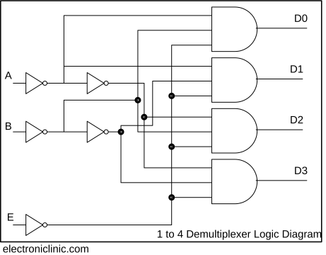
Demultiplexer In Digital Electronics Block Diagram Truth Table Logic Diagram
Logic Flowchart. Systems Flowchart. Product Flowchart. Process Flowchart. Additional flowchart types defined by others include: Swimlane Diagram, a.k.a Swimlane Flowchart: To delineate who does what in cross-team processes. Workflow Flowchart: To document workflows, often involving tasks, documents and information in offices.
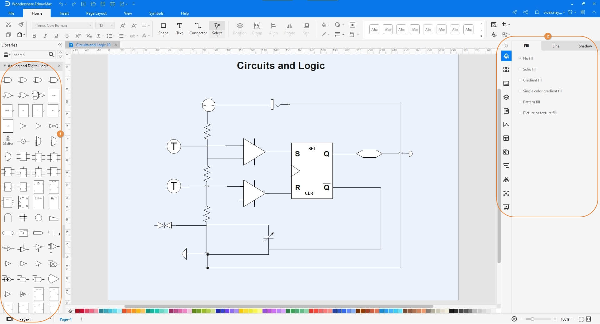
Circuit Diagram Symbols A Complete List Edrawmax
Besides the logic diagram tool, we've put together some logic diagram templates to help. The logic diagram consists of gates and symbols that can directly replace an expression in Boolean arithmetic. A logic gate is a device that can perform one or all of the Boolean logic operations AND, NAND, NOR, NOT, OR, XNOR, and XOR. Logic Flowchart.
The Diagram Of A Logic Circuit Is Given Below The Output Class 12 Physics Cbse
06.06.2018 · Logic gates using the programmable logic controller (PLC) is the basic thing you must learn if you want to enhance your Electrical and Electronics skills. In this post, you will be learned to write the programming in PLC using Logic Gates. For programmable logic controllers (PLCs) programming you need PLC software to build the logic module.
1
<link rel="stylesheet" href="static/css/noscript.css"/><h1>Logic.ly</h1><p>Please activate JavaScript to run Logic.ly in your web browser.</p>
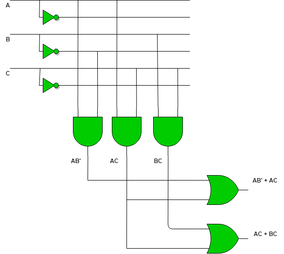
Programmable Logic Array Geeksforgeeks
In model theory, a branch of mathematical logic, the diagram of a structure is a simple but powerful concept for proving useful properties of a theory, for example the amalgamation property and the joint embedding property, among others.. Definition. Let be a first-order language and be a theory over .For a model of one expands to a new language

3 Logic Circuits Boolean Algebra And Truth Tables Dr Stienecker S Site
It uses logic symbols to show the main concept of the circuit. Detailed diagrams take the basic information and add specifics or non-logic data. This data may ...
Network And Logical Diagram Download Scientific Diagram
Q-Logic Technical Manual www.prideservice.com 7 I. OVERVIEW Q-LOGIC MODULES The basic system is a power module and a hand control. For adjusting seat position, an AAM module is added. For users who require specialized input devices, several options are available. This is a true plug-and-play system, and modules are
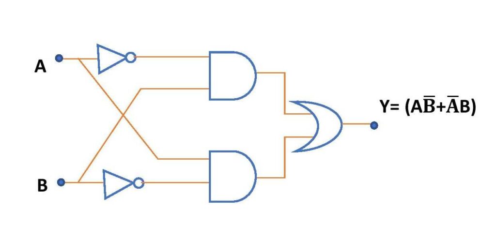
Xor Gate Circuit Diagram Using Only Nand Or Nor Gate Edumir Physics
Logic diagrams have several applications in investigations, and are most often developed in an iterative fashion. As shown in the event tree logic diagram in Figure 31.4, in the early stages of an investigation they can be used to illustrate credibly possible reasons, conditions, and events to assist in determining the cause scenario.As shown in Figure 31.5, they can point the investigators to ...

The Logic Circuit Corresponding To The Full Adder Of Fig 6 Three Not Download Scientific Diagram

Electric And Electronic Circuit Diagram Symbols Set Of Digital Electronics Logic Gate Stock Illustration Download Image Now Istock
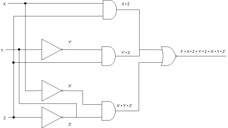
Example Logic Circuit 1
Logic Diagram Software
What Is Relay Logic Compare Ladder Logic And Relay Logic
What Is Ladder Diagram Edrawmax Online
Circuit Diagram A Circuit Diagram Maker
Circuit Simplification Examples Boolean Algebra Electronics Textbook
Logic Diagram Software
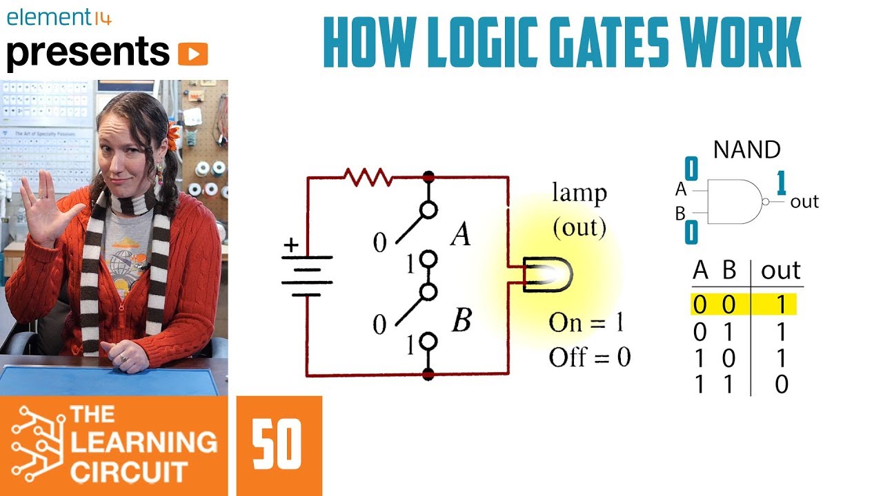
How Logic Gates Work The Learning Circuit Youtube
Circuit Diagram Edrawmax

An Example Of Business Logic Diagram Download Scientific Diagram
A Logic Diagram Of Arithmetic Circuit Download Scientific Diagram
Logic Diagrams And Prints

Whats The Difference Between Control Logic Diagram And Block Diagram

What Is Logic Diagram And Truth Table

What Are Digital Logic Circuits With Their Differences

Flow And Logic Diagrams

File Full Adder Logic Diagram Svg Wikimedia Commons
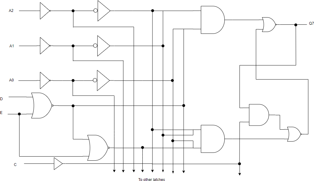
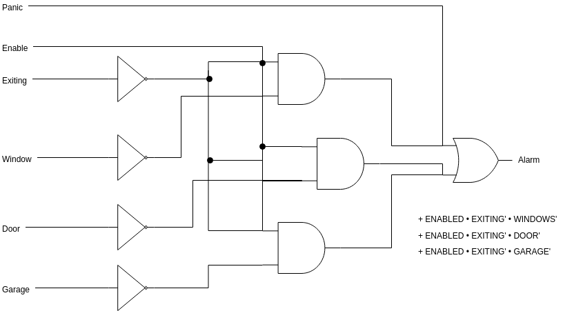
What Do Black Dots Represent On A Combination Logic Circuit Diagram Stack Overflow
Relay Logic Wikipedia

Pin On Electricity
Combinational Logic Circuits Definition Examples And Applications
0 Response to "34 what is a logic diagram"
Post a Comment