34 refrigeration cycle diagram pdf
Actual Vapor‐Compression Refrigeration Cycle Fig. 5-4: T-s diagram for actual vapor-compression cycle. Most of the differences between the ideal and the actual cycles are because of the irreversibilities in various components which are: 1-In practice, the refrigerant enters the compressor at state 1, slightly superheated vapor, ... refrigerators, and the cycles on which they operate ... Schmatic and T-s Diagram for Ideal Vapor- ... The Ideal Vapor-Compression Refrigeration Cycle.25 pages
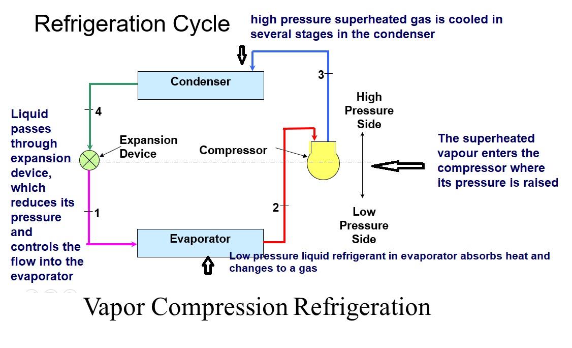
THE IDEAL VAPOR-COMPRESSION REFRIGERATION CYCLE The vapor-compression refrigeration cycle is the ideal model for refrigeration systems. Unlike the reversed Carnot cycle, the refrigerant is vaporized completely before it is compressed and the turbine is replaced with a throttling device. Schematic and T-s diagram for the ideal vapor-compression ...

Refrigeration cycle diagram pdf
producing cycle, as those reviewed under . Chapter 17: Power, would produce a refrigeration effect if run backwards in the T-s diagram. Most of the time, heat pumps (used for heating) are considered under the refrigeration heading, since the ... Q >0 in the refrigeration case (heat inputs), and Q Figure 10: Carnot refrigeration cycle ; (a) schematic diagram and (b) T – S Diagram for Carnot Cycle 25 Figure 11: Refrigerant Safety Group Classifications 30 Figure 12: p-h diagram for vapor compression cycle (ideal) 34 Figure 13: p-h Diagram for vapor compression cycle (actual) 36 Figure 14: Subcooling liquid from condenser 38 The vapor compression refrigeration cycle is a common method for ... constant temperature reservoirs and the T-s diagram for the working fluid.15 pages
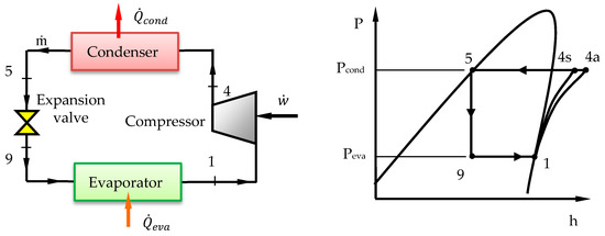
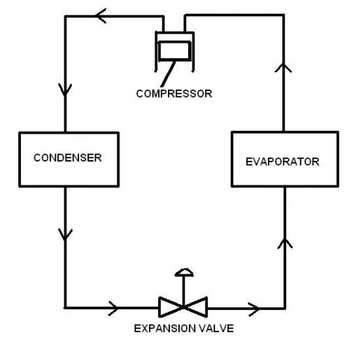
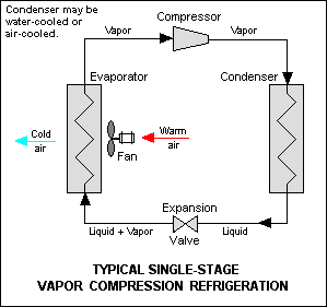
Refrigeration cycle diagram pdf. The refrigeration cycles can also be represented in a P-H diagram. Figure 5: P-H diagram representation of a dry refrigeration cycle. 4 key components needed in a basic refrigera=on cycle: 1. Compressor. 2. Condenser. 3. Evaporator ... Compresses low pressure refrigerant vapor from the.16 pages Refrigeration cycle is the basis of all refrigeration systems. So refrigeration cycle should be known to understand the refrigeration system. Some basic refrigeration cycles are discussed here through different diagrams. 2.2 VAPOUR COMPRESSION CYCLE Vapour compression cycle is an improved type of air refrigeration cycle in which a suitable ... by LOHW LIONG · 2012 — Reversed Carnot Cycle. 8. 2.2. Ideal vapor compression refrigeration cycle (a) T-s diagram, (b) P-h diagram. 10. 2.3. Schematic diagram of the vapor ...24 pages
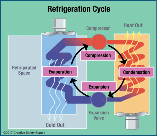
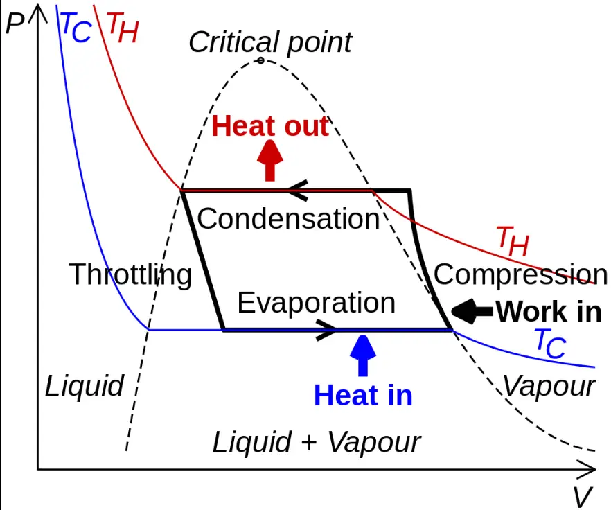
This is how the refrigeration cycle diagram looks: Yeah, it seems complicated at first, but it will be easier to understand once I have explained the refrigeration cycle diagram section by section. It important to understand the basic refrigeration cycle, to comprehend what is going on within the air conditioner units, we cannot see it. The log p-h diagram shows the thermodynamic state vari- ables in the respective phase. • pressure p. • specific enthalpy h. • temperature T. • specific volume v. Refrigeration Cycle Evaporator Condenser / Receiver Expansion Device. Vapor Compression Cycle. Th MOVEMENT Cooling by the removal of heat The MOVEMENT of HEAT from a place where it is notot a ted to a wanted to a place where it is unobjectionable. How Heat is Removed. What is heat? A form of energy What is cold? Carnot cycle, here the enclosed area is a rectangle. This cycle is often used as a comparison cycle to describe the quality of the cyclic process. The direction of the cyclic process in theT-s diagram determines w hether this is a heat pump cycle (refrigeration cycle) or a work machine cycle (steam power cycle). Refrigeration cycles are anti-
Figure 4: Wet refrigeration Cycle - The expander has been substituted by a throttling valve. If an expander had been used the line from d to a would be a vertical line. This is also done for mechanical reasons. The refrigeration cycles can also be represented in a P-H diagram. Figure 5: P-H diagram representation of a dry refrigeration cycle REFRIGERATION CYCLE The vapor-compression refrigeration cycle is the ideal model for refrigeration systems. Unlike the reversed Carnot cycle, the refrigerant is vaporized completely before it is compressed and the turbine is replaced with a throttling device. 5 Schematic and T-s diagram for the ideal vapor-compression refrigeration cycle. Pressure-enthalpy diagram for refrigerants ... Alternatives to vapor compression refrigeration system ... Compression Refrigeration Cycle. Component.50 pages The vapor compression refrigeration cycle is a common method for ... constant temperature reservoirs and the T-s diagram for the working fluid.15 pages
Auto Cascade Refrigeration System Hermawan S Blog Refrigeration And Air Conditioning Systems
Figure 10: Carnot refrigeration cycle ; (a) schematic diagram and (b) T – S Diagram for Carnot Cycle 25 Figure 11: Refrigerant Safety Group Classifications 30 Figure 12: p-h diagram for vapor compression cycle (ideal) 34 Figure 13: p-h Diagram for vapor compression cycle (actual) 36 Figure 14: Subcooling liquid from condenser 38
Marine Refrigeration Plants Refrigeration Of Cargo Spaces And Storerooms
producing cycle, as those reviewed under . Chapter 17: Power, would produce a refrigeration effect if run backwards in the T-s diagram. Most of the time, heat pumps (used for heating) are considered under the refrigeration heading, since the ... Q >0 in the refrigeration case (heat inputs), and Q
1
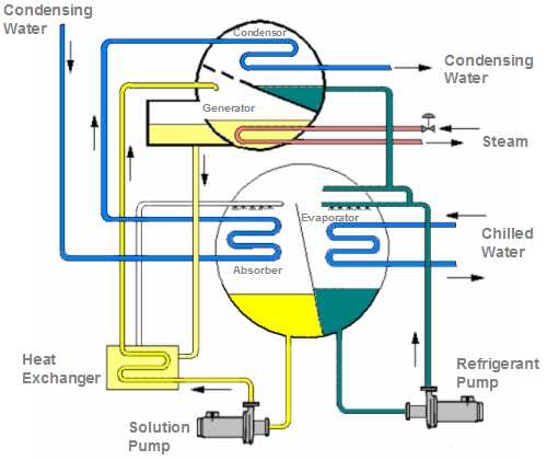
Absorption Chiller Pump

Types Of Refrigeration System Classification Of Refrigeration
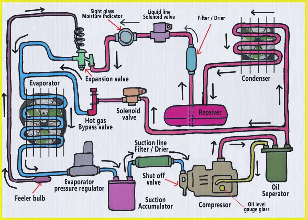
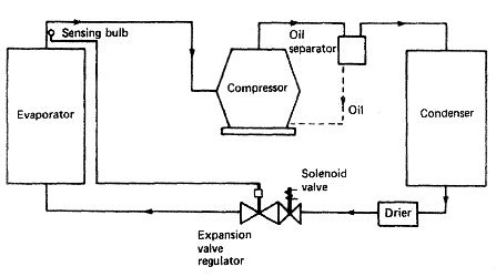
15 Major Components And Controls Of Refrigeration System Refconhvac Com

Conception Of An Absorption Refrigerating System Operating At Low Enthalpy Sources Intechopen
Ammonia Refrigeration Creative Safety Supply

Products

Refrigeration Cycle An Overview Sciencedirect Topics
Processes Free Full Text Performance Analysis And Working Fluid Selection For Single And Two Stages Vapor Compression Refrigeration Cycles Html
Vapour Compression Refrigeration Cycle Components Working Process Applications Pdf

Simple Refrigeration Cycle Hindi Urdu Youtube Refrigerator Refrigeration And Air Conditioning Electrical Circuit Diagram

Analysis Of A Refrigeration Cycle With Coolprop Pdf Pdf Refrigeration Energy Technology

Typical Refrigeration Cycle Diagram Royalty Free Cliparts Vectors And Stock Illustration Image 21930696
2
Refrigeration Onboard Ships
1
Refrigeration Systems
1

The Basic Refrigeration Cycle 2003 06 25 Achrnews Achr News

Thermal Efficiency Of Refrigeration System
2

Performance Analysis And Development Of A Refrigeration Cycle Through Various Environmentally Friendly Refrigerants Springerlink

Draw A Neat Sketch Of Vapour Compression Refrigeration Cycle Describe Its Working Mechanical Engg Diploma Simple Notes Solved Papers And Videos
Bum Email Mirare Vapor Compression Refrigeration System Classification Pdf Mysouthamptonshores Com
A Ton Of Refrigeration Effect Is Defined As The

Pdf Vapour Compression Cycle
2

Actual Vapour Compression Cycle And The Effect Of Suction And Discharge Pressure

Refrigeration Cycles Mech Engineering Thermodynamics Ucl Wiki

Cascade Refrigeration Wikipedia
2
2
0 Response to "34 refrigeration cycle diagram pdf"
Post a Comment