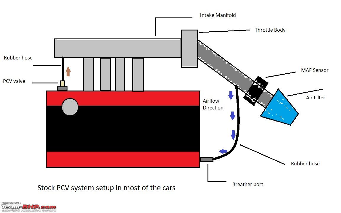
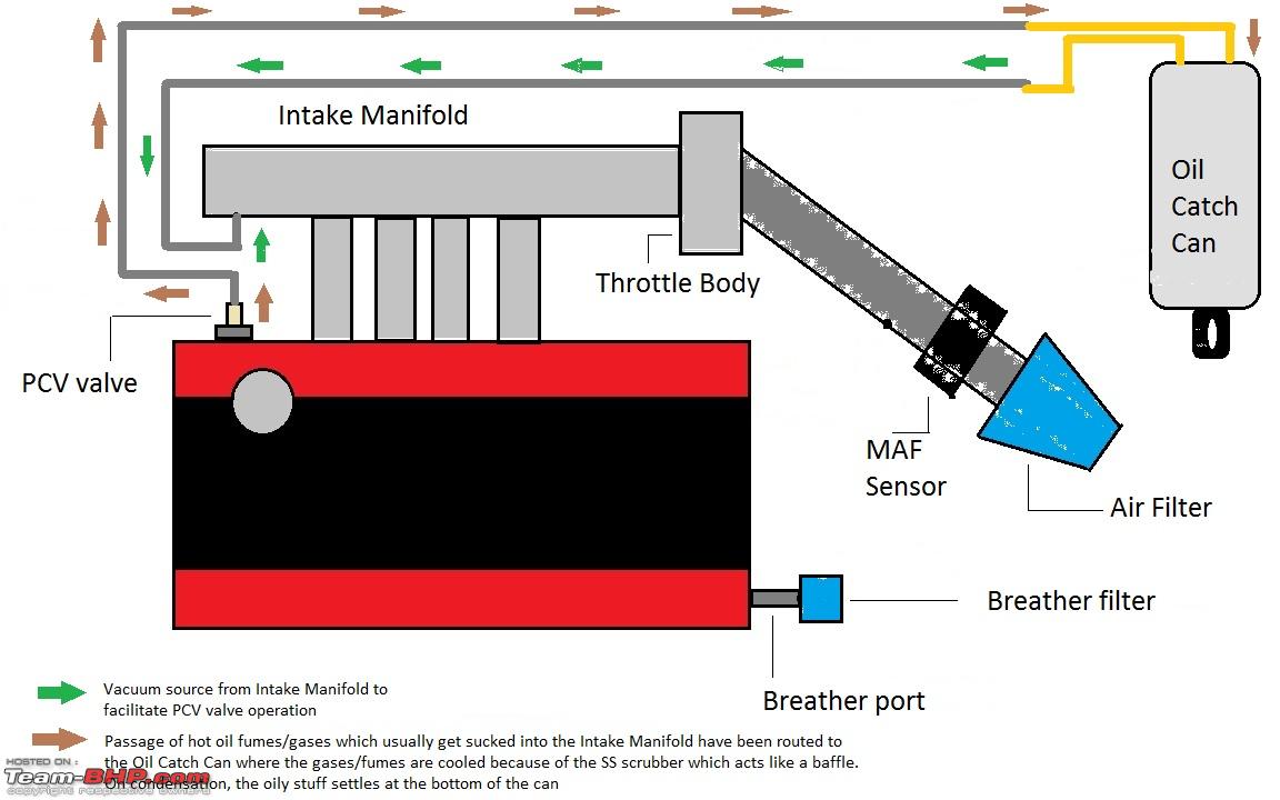
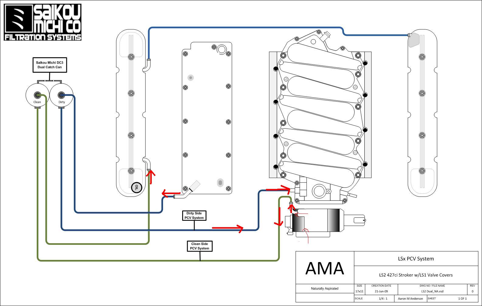
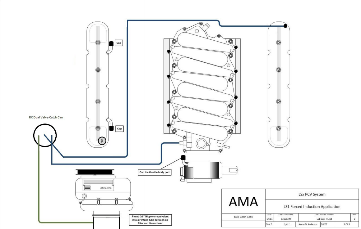
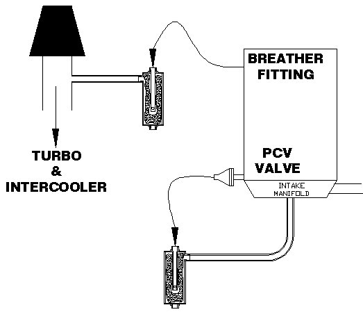
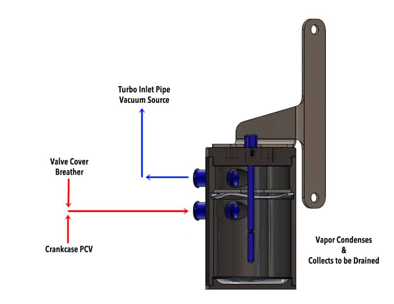
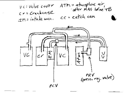
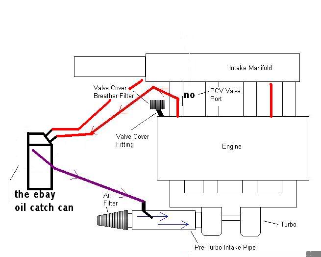
38 oil catch can installation diagram
How To Install An Oil Catch Can - PowerNation Apr 10, 2019 · It has a mesh screen and filter material that traps the oil and vapor. It also has an easily accessible drain. To get started installing, run lines from each vent on the LS valve covers which will route up to the catch can that has fittings on either side. The catch can will be mounted somewhere in the engine bay. Oil Catch Can - DIY : 3 Steps - Instructables The catch can described in this article will sort of mimic the same principle, although the catch can will vent to open atmosphere. The reason for this is particular, my car no longer is fuel injected, and instead uses carburetors, so the valve cover was disconnected - and in being so, oil would soil the engine bay.
Setting up and Installing the best Catch Can - Car Engine ... Start with a large catch can that has several inlets into baffled areas with filtering elements. Those areas should then drain to an area below while air can ...
Oil catch can installation diagram
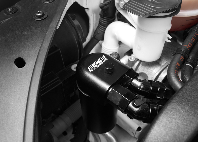
Catch Can Installation Diagrams - McNally Electronics Inc. Gen 2 Oil Catch Can by McNally Gen 2 CC written installation instructions Gen 2 CC written installation diagram Gen 2 CC written installation diagram for FORD 1.6L - 2.0L -2.3L PFDI Engines Gen 2 CC written installation diagram for FORD 3.5L - 2.7L GTDI Engines Gen 2 CC written installation diagram for FORD 5.0L - 7.3L PFDI Engines Performance Baffled Oil Catch Can & Oil Drain System ... CATCH CAN INSTALLATION GUIDELINES System Diagram: Catch can Catch can Intake pipe Intake pipe Standard Flow Shown Below: Reverse Flow Shown Below: Reverse Flow Shown Below: PCV assembly PCV assembly Standard Flow Shown Below: FEED RETURN RETURN FEED Select one of the following: • Click HERE for catch can flow reversal. • Click HERE for catch Baffled Oil Catch Can System Installation Guide - Rackcdn.com PERFORMANCE BAFFLED OIL CATCH CAN INSTALLATION GUIDE. 2. . © 2019 ECS TUNING ... look at the catch can drain system, the diagram on the.
Oil catch can installation diagram. Catch Cans: Keeping the Oil Out - AmericanMuscle.com The diagram below illustrates the basics of how a catch can works. The purple arrow represents the air/oil blow-by mixture coming in from the crankcase. It enters the catch can where the oil is collected at the bottom. The air is forced through a media, which filters out additional contaminants, before exiting the catch can as cleaned air (green arrow) to be re-circulated back into the intake manifold. Baffled Oil Catch Can System Installation Guide - Rackcdn.com PERFORMANCE BAFFLED OIL CATCH CAN INSTALLATION GUIDE. 2. . © 2019 ECS TUNING ... look at the catch can drain system, the diagram on the. Performance Baffled Oil Catch Can & Oil Drain System ... CATCH CAN INSTALLATION GUIDELINES System Diagram: Catch can Catch can Intake pipe Intake pipe Standard Flow Shown Below: Reverse Flow Shown Below: Reverse Flow Shown Below: PCV assembly PCV assembly Standard Flow Shown Below: FEED RETURN RETURN FEED Select one of the following: • Click HERE for catch can flow reversal. • Click HERE for catch Catch Can Installation Diagrams - McNally Electronics Inc. Gen 2 Oil Catch Can by McNally Gen 2 CC written installation instructions Gen 2 CC written installation diagram Gen 2 CC written installation diagram for FORD 1.6L - 2.0L -2.3L PFDI Engines Gen 2 CC written installation diagram for FORD 3.5L - 2.7L GTDI Engines Gen 2 CC written installation diagram for FORD 5.0L - 7.3L PFDI Engines






![Schematic diagram of the oil catch can [7]. | Download ...](https://www.researchgate.net/profile/Luis-Rojas-Solorzano/publication/283300310/figure/fig2/AS:668643729891331@1536428496073/Schematic-diagram-of-the-oil-catch-can-7_Q640.jpg)






0 Response to "38 oil catch can installation diagram"
Post a Comment