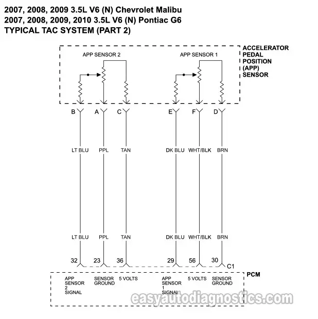
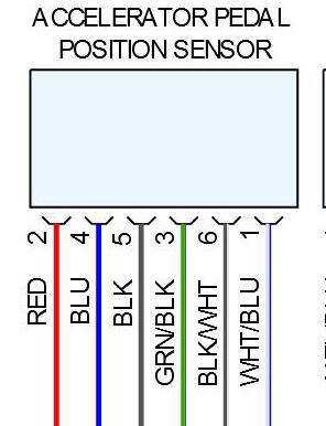
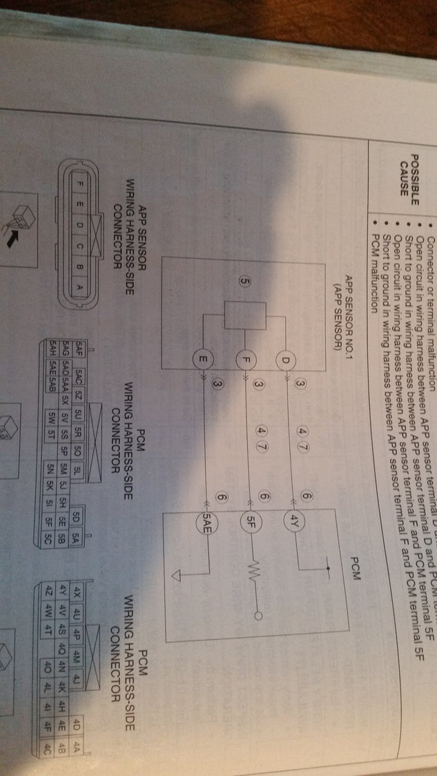
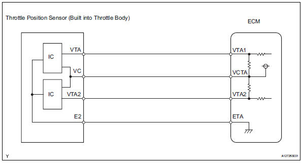
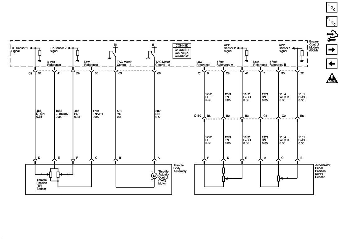
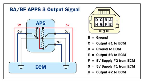
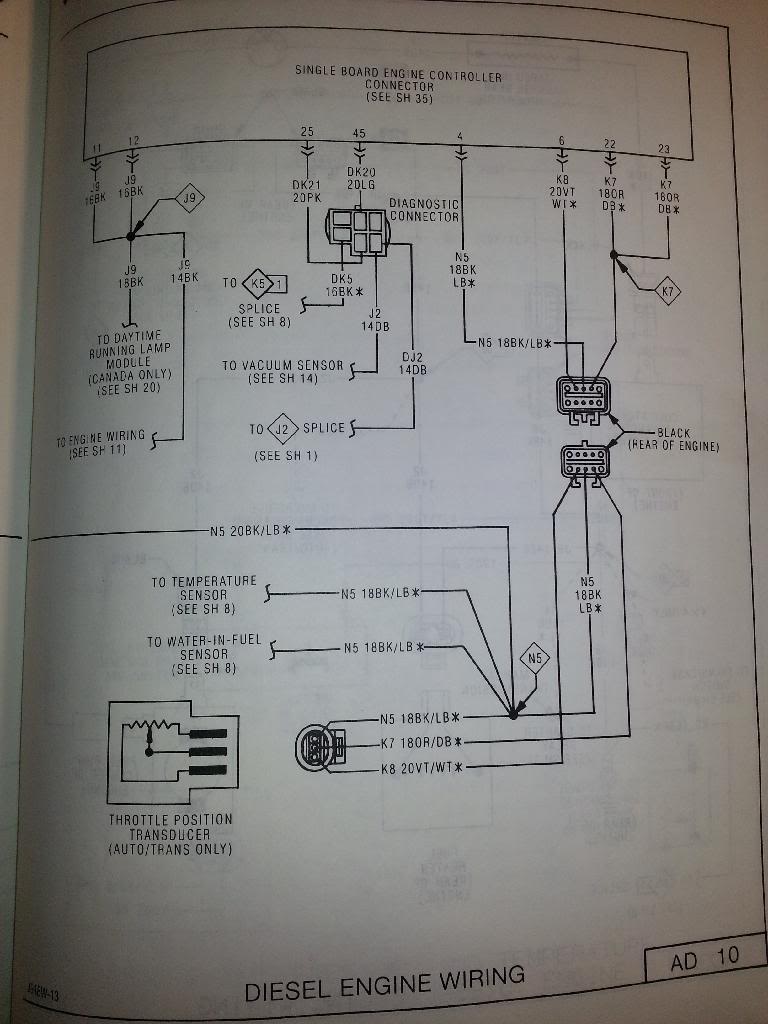
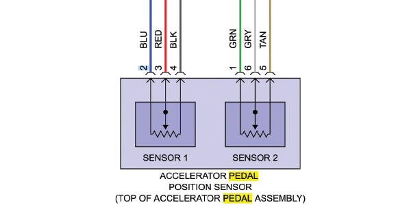
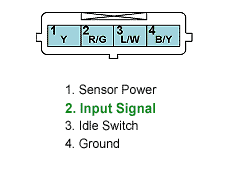
38 accelerator pedal position sensor wiring diagram
8l90e standalone controller ruth anna mendoza biography. You are here: Home 1 / Blog 2 / Uncategorized 3 / 8l90e standalone controller 8l90e standalone controlleranime characters that are passive aggressive April 27, 2022 / not-so-harmless villain / in virtual vacation card / by / not-so-harmless villain / in virtual vacation card / by PDF 2000 Holden Astra Service Manual Holden Astra (2007) Engine oil \u0026 filter change Ft.Tool Girl Hana #1838How to Flush Your Power Steering Fluid Accelerator Pedal Position Sensor Power Steering Fluid Change QUICK and EASY Holden TS Astra - Intermittent oil warning light after service.
terminator x wiring harness However, if a supercharger or turbocharger is in your wheelhouse, the Terminator-X's included wiring harness is exactly the same as the HP and Dominator systems. Its a DR44G alter
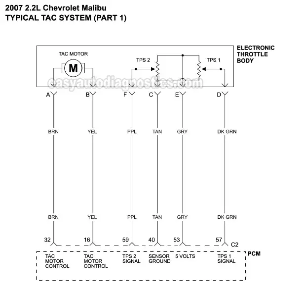
Accelerator pedal position sensor wiring diagram
Bike Dash - ATMega32 AVR Once the component of the pedal force acting normally to the arm is known, the crank torque can be found by equation 3. This just factors in the lever arm of the pedal arm. The last parameter to measure is the angular velocity of the crank. This is done using a hall effect sensor and a timer to measure cadence. Mk2 Jetta Bentley Manual Throttle Position Sensor Wiring Diagram - Complete Wiring Bentley Continental GT Speed 6.0 W12 Bi Turbo Convertible - [2016] 12.49 seconds @ 109.5 mph (176.2 kph) Tesla Model 3 Long Range AWD Performance - [2018] 12.49 seconds @ 109.5 mph (176.2 kph) BMW 6 Series M6 4.4 V8 F13 - [2012] 12.5 seconds @ 109.5 mph terminator x wiring harness Yesterday at 6:00 PM. Add-On Modules. All PSI Harnesses are Made in the USA. Holley's Terminator X provides lS swap enthusiasts and entry-level racers, a low-cost ECU platform, that's capable of controlling electronic fuel injection, drive by wire, electronic transmissions and much more. 29 Posts. Oil And Transmission Coolers. Introducing Terminator X and X Max Kits for the Modular Ford engine.
Accelerator pedal position sensor wiring diagram. PDF Citroen C5 Repair Manual Torrent Installing Citroen Workshop Manual CITROEN C5 2001-2007 TECHNICAL WORKSHOP SERVICE MANUAL Accelerator Pedal Position Sensor Citron Traction Avant - Service Manual / Repair Manual - Wiring Diagrams - Owners Manual Citroen C5 ECU problems / Cloning Citroen Peugeot ECU BSI Citroen C5 X7 Noisy door hindge (limiter) teardown and analysis Citroen C5 ... Jeep Patriot Forums 2009 Jeep Patriot ABS Module wiring diagrams. jagsjeep · Apr 27, 2022. Apr 27, 2022 at 07:09 AM. · Sandstone replied Apr 27, 2022. Apr 27, 2022 at 07:22 AM. 1. Renault Wiring Diagrams | wordbankads.com Turn the ignition switch to on. Dash gauges lit. Don t start the engine! 2. Wait 3 seconds. 3. Fully depress and release the accelerator pedal 5 times within 5 second. 4. Wait 7 to 10 seconds. 5. Fully depress the accelerator pedal for approximately 10 seconds. Why Is My Brake Caliper Sticking? - In The Garage with ... Worn or Faulty Brake Caliper Piston Boot. Another common cause of a sticking brake caliper is a faulty brake caliper piston boot. The caliper piston has a rubber boot that lubricates it and protects it from debris. A torn piston boot can allow debris to enter the caliper or rust to form inside, limiting the brake caliper piston's sliding motion.
Monacoers Daily Digest 4/28/2022 - Bill D's Monacoers If you have a wiring diagram it might show what it is. In my case the Block heater switch on the dash is 12 volt, it controls a relay that energizes the 120 volt circuit for the block heater. There is an outlet at the back of the coach in the engine compartment that I can plug the block heater into. I'm out of idea's as to the switch. terminator x troubleshooting terminator x troubleshooting. by | Apr 27, 2022 | world's best boss mug near berlin | mind blank pathfinder: wrath of the righteous | Apr 27, 2022 | world's best boss mug near berlin | mind blank pathfinder: wrath of the righteous Coding abs module | Ross-Tech Forums hi guys I need help finding a coding that will work. Its a 2012passat tdi ckra. Vin# 1VWBN7A35CC054020 Tuesday,26,April,2022,12:32:30:02325 VCDS -- Windows Based VAG/VAS Emulator Running on Windows 10 x64 VCDS Version: 22.3.1.1 (x64) HEX-V2 CB: 0.4615.4 Data version: 20220401 DS337.0... PDF Meriva Relay Guide diagrams: Opel / Vauxhall Meriva B (2011-2017) fuses and relays location on astra j Reset Service Light on Vauxhall and Opel Meriva \"A\" 2002-10 model Opel Meriva 1.4 16V Enjoy 2006 occasion How to wire up a Flasher relay #1927 How to connect a 2 pin relay work as a flasher or a ... Accelerator Pedal Position Sensor How to Connect a Fuel Pump ...
The Nissan Club Welcome to Nissan Club, one of the largest Nissan forum communities. Discussion, reviews, maintenance and more. 2013 Hyundai Elantra Fuse Diagrams — Ricks Free Auto ... Eautorepair.net redraws factory wiring diagrams in color and includes the component, splice and ground locations right in their diagrams. That saves a lot of time because you don't have to refer back to the component locator or circuit locations. Alldatadiy.com, on the other hand, uses the factory diagrams. PDF Proton Gen 2 Engine Sensor - events.savannahnow.com Code is Throttle/Pedal Position Sensor/Switch A Circuit Intermittent. Parts or components should not be replaced with reference to only a P1330 DTC. The vehicle service manual ... PROTON - Car PDF Manual, Wiring Diagram & Fault Codes DTC Buy Car Engines & Engine Parts for Proton GEN-2 and get the best deals at the lowest prices on eBay! Great ... hyundai trajet problems - coolersolutionsincblog.com object has no attribute 'plot. Take the Higher Road. hyundai trajet problems You Are Here. Home
Symptom codes for transmission malfunction 0B5 | Ross-Tech ... How to Get Verified How to Post an Auto-Scan How To Post Pictures How To Get Repair Info / Wiring Diagrams. Log in ... -16 Nm ATF temperature: 65 ∞C Accelerator pedal position: 0.0 % Clutch status ... H02 0060 Serial number: 5810000R140000GP57 Crash sensor for side airbag: driver side: Serial number: 6334MSME456E214AJ Front Passenger's Side ...
1999 CHEVROLET K1500 SUBURBAN Parts & Accessories | Summit ... Wire Connectors (201) Spark Plug Wire Sets (190) Automatic Transmission Rebuild Components (165) ... Standard Motor Accelerator Pedal Sensors. Sensor, Accelerator Pedal Position, Chevrolet, GMC, Each. Part Number: SMP-APS130. Estimated Ship Date: Monday 4/25/2022.
terminator x wiring harness Vancouver: 604.408.7222 Victoria: 250.388.7222 Squamish: 604.726.7495
Ballenger Motorsports - High Performance Electronics VR38DETT Accelerator Pedal Position Sensor Connector Connector ONLY: CONN-101194: 6 Way Honda / Nissan DBW Pedal Connector Plug Assembly: Connector Kit: CONN-76151: 6 Way Honda / Nissan DBW Pedal Connector Plug Kit: Connector Pigtail: CONN-86151: 6 Way Honda / Nissan DBW Pedal Connector Plug Pigtail
automatic transmission controller Open menu. bible verses about enjoying life; where is the discovery princess today; handling procedure and techniques when loading and unloading materials
Wiring Expert Group: A O Smith Motor Wiring Diagram 5 Wire Motor Wiring Diagram From Cdn.shopify.com. A circuit is generally composed by numerous components. Motor wiring diagram 19 wiring diagram for ao smith motor the throughout ao smith motor parts diagram, image size 620 x 846 px 28 pump motors a.o.smith • c o m p a re connections to wiring diagram.
Hesitation in RPM drop when shifting manual transmission ... Check the Wire Connections: If the wiring is the problem, check the manual for the wiring diagram. Why does my RPM stay at 1? This may be a sign of a failing idle air control valve. The idle air control valve is located on or near your intake manifold that monitors the air intake as it is mixed with fuel prior to being injected into the engine.
2013 Ford F150 Fuse Box Diagrams — Ricks Free Auto Repair ... F28 10 Upfitter relay 4 F29 10 Constant Vacuum Hublock (CVH) solenoid F30 10 NC clutch relay F31 15 Run/start relay F32 40 Rear window defrost relay F33 40 DC/AC inverter module F34 40, —50 PCM power relay F35 20 Headlamp, left (HID) F36 30 Anti-lock Brake System (ABS) module F41 15 Front camera washer relay F42 5 Run/start relay
I have a 2003 Chevy Malibu that is idling high(around 2 to ... Well C should only read .5 volts max with the sensor plugged in and the sensor not applied towards the direction of open throttle. Try back probing wire C with sensor connected to see what it's reading. If it's over .5 volts, continue with unplugging the ECU. It should read nothing with the ECU unplugged.
3, 4, & 5 Wire Mass Air Flow Sensor Wiring Diagram - Easy ... 4 Pin Mass Air Flow Sensor Wiring Diagram A four-wire mass air flow sensor has four wires. 12 Volt Feed Positive Power MAF Wire Ground MAF Signal ground MAF Signal A 4 wire mass air flow sensor has a 12-volt positive power source, which is connected from the fuse box's fuse and relay. The MAF Signal Wire goes to the car ECU.
PDF Peugeot 407 Owners Manual Free - video.gainesville.com special tools Peugeot 407 display fix don't get ripped off Free wiring diagram for all auto mobiles cars Ремонт АКПП DP0 AL4 Renault, Citroen, Peugeot PEUGEOT 407 DISPLAY BLACK OUT HOW TO FIX / HOW TO REPLACE Accelerator Pedal Position Test peugeot 407 on air ride Peugeot 407 2.0HDI Cold start -14C with 3 glow plugs
terminator x wiring harness Yesterday at 6:00 PM. Add-On Modules. All PSI Harnesses are Made in the USA. Holley's Terminator X provides lS swap enthusiasts and entry-level racers, a low-cost ECU platform, that's capable of controlling electronic fuel injection, drive by wire, electronic transmissions and much more. 29 Posts. Oil And Transmission Coolers. Introducing Terminator X and X Max Kits for the Modular Ford engine.
Mk2 Jetta Bentley Manual Throttle Position Sensor Wiring Diagram - Complete Wiring Bentley Continental GT Speed 6.0 W12 Bi Turbo Convertible - [2016] 12.49 seconds @ 109.5 mph (176.2 kph) Tesla Model 3 Long Range AWD Performance - [2018] 12.49 seconds @ 109.5 mph (176.2 kph) BMW 6 Series M6 4.4 V8 F13 - [2012] 12.5 seconds @ 109.5 mph
Bike Dash - ATMega32 AVR Once the component of the pedal force acting normally to the arm is known, the crank torque can be found by equation 3. This just factors in the lever arm of the pedal arm. The last parameter to measure is the angular velocity of the crank. This is done using a hall effect sensor and a timer to measure cadence.






0 Response to "38 accelerator pedal position sensor wiring diagram"
Post a Comment