37 mallory unilite wiring diagram
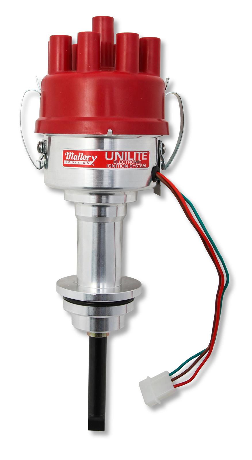
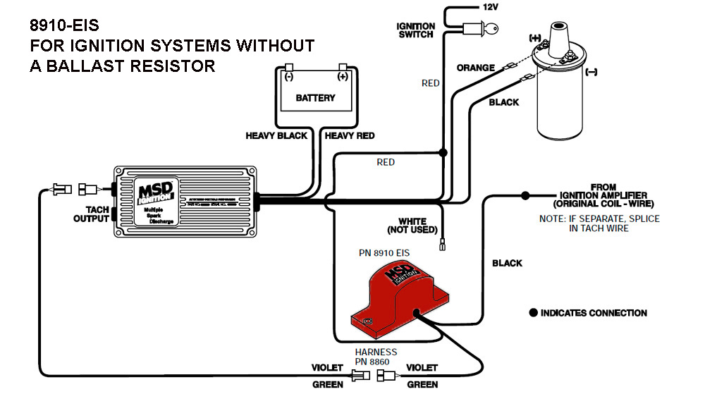
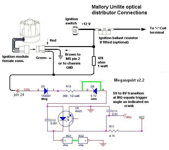
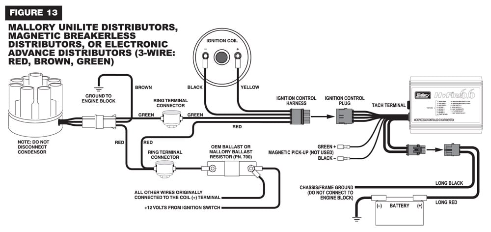
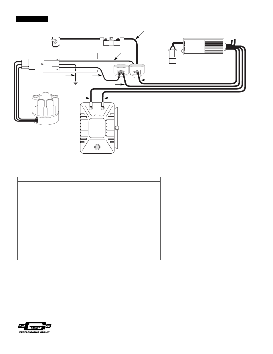
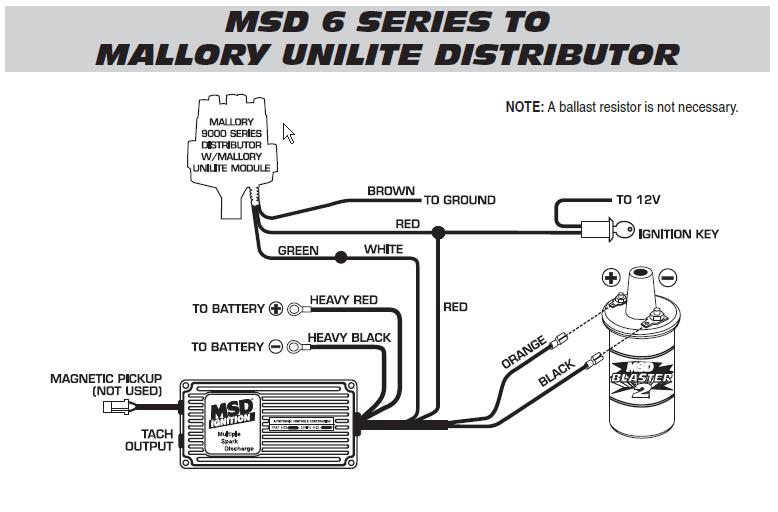
MSD 6AL to Mallory Unilite - Holley -the unilite has 3 wires---brown, green and red. -the brown goes to ground. -the green connects to the MSD white. -the red connects to the small red of the MSD and both of these get power from the key switch----and no resistor is needed between the key and these two reds. --------------------------------------------- How to Troubleshoot a Mallory Unilite Distributor With No ... Step 2 Check the positive side of the coil for the proper voltage, be it 12 or 6 volts. Repair the wiring if the voltage is not correct. Move the red probe to the negative terminal of the coil. The voltage should be the same. If not replace the coil. Step 3 Remove the distributor cap and pull off the rotor.
msd 6al and unilite question - NastyZ28.com Lifetime Gold Member. Jul 8, 2001. 23,694. Gallatin Tennessee. i'm running a msd 6A and mallory unilite and the tach is hooked up to the port of the msd box. Apr 17, 2008. #8.
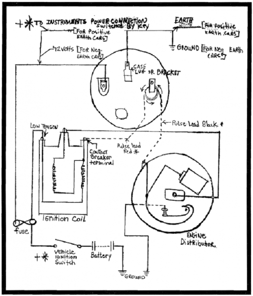
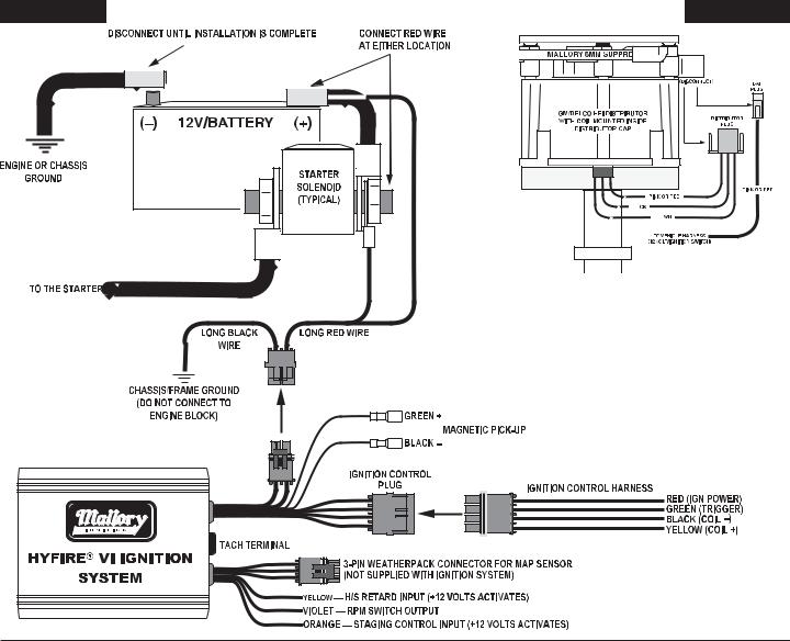
Mallory unilite wiring diagram
Mallory Comp 9000 Distributor Wiring Diagram Mallory 9000 Wiring Diagram Unilite, Distributor, Installation instructions • Read online or download PDF • Mallory Ignition Mallory UNILITE DISTRIBUTOR User Manual. spark plug wires from the original distributor cap to the UNILITE. ®. Distributor cap in the same. ground, 12 volt electrical system with a distributor. Mallory Electronic Distributor Wiring Diagram - schematron.org UNILITE® Distributor vacuum chamber and the carburetor. 2 schematron.org MALLORY IGNITION-+ COIL FIGURE 1 UNILITE® WIRING DIAGRAM USING BALLAST RESISTOR NOTE: The purpose of an ignition ballast resistor between the ignition switch (12V) and the ignition coil positive terminal is to restrict current flow through the ignition coil. Mallory Tachometer Wiring Diagram - schematron.org Mallory PRO TACH® I, IV and IV. NOTE: Mount the Mallory Fuel Injection/Tach Adapter away from hot Wiring diagrams for this unit are shown on the back of this instructions sheet. RED.ignition wire, such as Mallory PRO SIDEWINDER by the actual tachometer manufacturer.
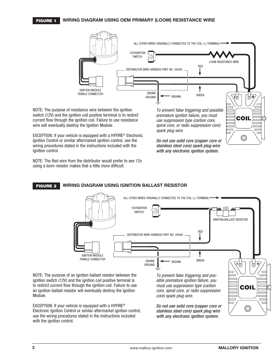
Mallory unilite wiring diagram. PDF Mallory Unilite Distributor Installation Instructions UNILITE® Distributor vacuum chamber and the carburetor. 2 MALLORY IGNITION-+ COIL FIGURE 1 UNILITE® WIRING DIAGRAM USING BALLAST RESISTOR NOTE: The purpose of an ignition ballast resistor between the ignition switch (12V) and the ignition coil positive terminal is to restrict current flow through the ignition coil. Mallory Ignition Mallory UNILITE DISTRIBUTOR User Manual UNILITE ® DISTRIBUTOR INSTALLATION Step 1 Remove the distributor cap from the UNILITE ® Distributor. Step 2 Place the UNILITE ® Distributor in the engine. Rotate the UNILITE ® Distributor housing in the opposite direction of rotor rotation until the nearest slot on the rotor's shutter wheel is aligned with the optical eye of the UNILITE ® Module. Mallory Unilite Ignition Wiring Diagram wiringall.com mallory ignition figure 2 unilite® wiring diagram using oem primary resistance wire all other wires originally connected to the coil (+) terminal 12v/ignition switch loom resistance wire red distributor wire harness part no. ignition module female connector + - green brown engine ground. Mallory Unilite Distributor Wiring Diagram - Wiring Schemas Mallory unilite distributor wiring diagram. 37, 38, 45 and 46 series distributorsuse mallory's unilite® module and can trigger either a hyfire capacitive discharge ignition or be run with just a coil. 29349 ignition ballast resistor brown green red Msd crank trigger to mallory ignition the 1947 present.
mallory unilite hookup - Hot Rod Forum according to mallory unilite installation diagram, i must use a ballast resister so as not to burn up the moduale in the distributor.. the instructions tell me to hook the red wire (from distributor) to the 12v side of the ballast, green wire to (-) side of coil, and brown wire to engine ground.... seems to me that the ballast resistor is not … PDF Mallory 501 Ignition Conversion Kit Installation Instructions pan no. sos — unilite. module assembly for future reference mallory inc. -delco - products 550 ual lory way, carson nevada page. 71 . rig green ... electronic distributor wiring diagram this is for mallory co!l 29217 and oem style cols only mallory 000 // 0 00 swttch promaster' wiring sass How do I wire my Mallory Distributor? - V8Wizard Just simply click an image below for the correct instructions pack that would be supplied with your Mallory distributor or for just a simple wiring diagram click the image that matches your setup. Mallory Unalite Instructions Mallory Dual Point Instructions wiring diagram for mallory ing.system - Hot Rod Forum Oh my gosh. You may have the worst electronic distributor ever designed. The Mallory Unilite deserves every bad thing said about it. You can blow a module in a heartbeat and be dead in the water without a replacement. The added insult is the cost of the module. Try about $90.00. That's almost half the price of the whole distributor.
PDF v8wizard.com WIRING DIAGRAM USING BALLAST RESISTOR ALL OTHER MRES CONNECTED TO THE TERMINAL SWITCH IGNITION BALLAST RESISTOR HARNESS PART NO. 29349 O GREEN BROWN IGNITION MODULE FEMALE CONNECTOR ENGINE GROUND - NOTE: The purpose of an ignition ballast resistor between the ignition switch (12V) and the ignition coil PDF UNILITE DISTRIBUTOR - Holley unilite® distributor vacuum chamber and the carburetor. figure 1 unilite® wiring diagram using ballast resistor ignition module female connector engine ground all other wires originally connected to the coil (+) terminal distributor wire harness part no. 29349 ignition ballast resistor pn 8214 brown green red Ignition Technical Support - Holley Next attach your Black voltmeter wire to an engine ground on a good ground source. We suggest a manifold, or header bolt. Most anywhere on the engine is good. Now the voltage should read about 11 to 12 volts at this point. Remember to turn the key on for this reading! 12 volts must be present on your voltmeter. mallory ignition wiring diagram unilite | Wirings Diagram Mallory Ignition Wiring Diagram - mallory comp 9000 unilite breakerless ignition wiring diagram, mallory electronic ignition wiring diagram, mallory hei ignition wiring diagram, Every electrical structure consists of various distinct components. Each part ought to be set and linked to other parts in particular way….
Mallory Unilite wiring | The H.A.M.B. - Jalopy Journal I ended up wiring the module to the coil side of the resistor, no problems since. I have no idea why they were blowing, or what I changed by moving the power wire to the coil side of the resistor, but it works. Mallory now makes the e-spark module which costs about half of what the Unilite modules do, and works fine.
mallory ignition wiring diagram | Wirings Diagram Mallory Ignition Wiring Diagram - mallory comp 9000 unilite breakerless ignition wiring diagram, mallory electronic ignition wiring diagram, mallory hei ignition wiring diagram, Every electrical structure consists of various distinct components. Each part ought to be set and linked to other parts in particular way….
Mallory Marine Distributor Wiring Diagram 2 wiringall.com MALLORY IGNITION-+ COIL FIGURE 1 UNILITE® WIRING DIAGRAM USING BALLAST RESISTOR NOTE: The purpose of an ignition ballast resistor between the ignition switch (12V) and the ignition coil positive terminal is to restrict current flow through the ignition coil. Failure to use an ignition ballast resistor will.
PDF UNILITE DISTRIBUTOR - Summit Racing Equipment The 3 wires coming from the UNILITE ® Distributor must be connected using the distributor wire harness furnished (see Figures 1 and 2). RED WIRE: If you use loom resistance wire, connect to the coil (+) terminal. If you use a ballast resistor, connect to 12 volt side of ballast resistor. GREEN WIRE: Connect to the coil (-) terminal.
PDF UNILITE DISTRIBUTOR - Summit Racing Equipment use a Mallory PROMASTER® Coil Part No 29440 or 29625, or Mallory Chrome Electronic Ignition Coil Part No. 29216. Spark Plug Wires: To prevent false triggering and premature ignition failures, use suppres-sion type spark plug wire.We recommend spiral core ignition wire, such as Mallory PRO SIDEWINDER® Ignition Wire. Spark Plug Gaps:
Mallory Unilite Wiring Diagram For Motorcycle 32+ Images ... A staple back in the 70's, the tried and true mallory unilite was the original performance distributor. The mallory unilite distributor is back! C72d mallory unilite wiring diagram for motorcycle. Mallory unilite wiring diagram : A single wire alternator with a poor diode will cause a voltage dump when the key is turned off.
Mallory Unlite Distributor wiring | British Car Forum Can anyone tell me if this is the correct wiring diagram to use for a Mallory Unilite distributor on a TR4? My coil which is a Mallory Electronic Distributor was bought specifically for my distributor .
Mallory Tachometer Wiring Diagram - schematron.org Mallory PRO TACH® I, IV and IV. NOTE: Mount the Mallory Fuel Injection/Tach Adapter away from hot Wiring diagrams for this unit are shown on the back of this instructions sheet. RED.ignition wire, such as Mallory PRO SIDEWINDER by the actual tachometer manufacturer.
Mallory Electronic Distributor Wiring Diagram - schematron.org UNILITE® Distributor vacuum chamber and the carburetor. 2 schematron.org MALLORY IGNITION-+ COIL FIGURE 1 UNILITE® WIRING DIAGRAM USING BALLAST RESISTOR NOTE: The purpose of an ignition ballast resistor between the ignition switch (12V) and the ignition coil positive terminal is to restrict current flow through the ignition coil.
Mallory Comp 9000 Distributor Wiring Diagram Mallory 9000 Wiring Diagram Unilite, Distributor, Installation instructions • Read online or download PDF • Mallory Ignition Mallory UNILITE DISTRIBUTOR User Manual. spark plug wires from the original distributor cap to the UNILITE. ®. Distributor cap in the same. ground, 12 volt electrical system with a distributor.




0 Response to "37 mallory unilite wiring diagram"
Post a Comment