39 4 way valve diagram
5/2 & 4/2-Way Pneumatic Valve - How They Work - Tameson The difference between the two valve types is the number of exhaust ports: A 5/2-way pneumatic valve has two independent exhaust ports. A 4/2-way valve has only one common exhaust port. Valve symbol of a mono-stable 4/2-way valve with ISO and alternative port designation. This means that both port (A,2) and (B,4) connect to exhaust port (R,3). Four-Way Solenoid Valves | McMaster-Carr Matching Flow Diagrams to Replace an Air Directional Control Valve. More. Choosing an Air Directional Control Valve. More. ... Also known as 4-way valves, these valves create two actions, such as extending and then retracting a double-acting cylinder. Apply voltage to the electrical connection to actuate.
part 5: four-way reversing valves - Danfoss Components for heat pumps - part 5: four-way reversing valves. Sunday, July 1, 2012. Four-way reversing valves are used to completely reverse the cycle of one-to-one heat pump systems. Such valves may be used to facilitate using the system for both heating and cooling, or to provide an effective and energetically optimized defrosting method.
4 way valve diagram
4-Way Directional Valve - MathWorks The 4-Way Directional Valve block represents a directional control valve with four ports and three positions, or flow paths. The ports connect to what in a typical model are a hydraulic pump (port P ), a storage tank (port T ), and a double-acting actuator (ports A and B ). Fluid can flow from the pump to the actuator via path P-A or P-B and ... GENERAL FOUR-WAY DIVERTER VALVE - Schlumberger The GENERAL Valve 4-Way Operator is a screw jack device designed to provide the necessary mechanical advantage and the “unseat, lift, turn and reseat” motion and seating force required by the GENERAL 4-Way Diverter Valve. Turning the handwheel clockwise causes the plug to lift and retract the seating slips. Four-Way Hydraulic Directional Control Valves | McMaster-Carr Place four-way valves between the pressure source and a double-acting cylinder. In NFPA diagrams, P represents the pressure source, T represents the tank, and A and B represent work ports. For technical drawings and 3-D models, click on a part number. Single-Solenoid Four-Way Valves—2 Flow Positions (4/2 Valves) Single-Solenoid Four-Way Valve 2 3 4
4 way valve diagram. PDF Air Control Valves 3-Way, 3-Port, 2-Position 4-Way, 4-Port ... "C/CW/CC" Series Air Control Valves 3-Way, 3-Port, 2-Position 4-Way, 4-Port, 2-Position Catalog 0640-E/USA April 2004 What is a 4-way Solenoid Valve? - Instrumentation Tools 4-way Solenoid Valve. The following diagram shows a 4-way solenoid valve connected to the piston actuator of a larger (process) ball valve: The same diagram could be drawn using the “triangle” solenoid valve symbols rather than the “block” symbols more common to fluid power diagrams: 4-Way Valve Flow Diagram - Heartland Owners Forum CHECK VALVE TO 4 FUNCTION FILL VALVE FROM CHECK VALVE TANK TO COLD FIXTURES AIR VENT FOR TANK 0 Anderson @Anderson Brass Company . TO TANK 0 Anderson O L—T0COLDFlXWRES o . Author: Bryan Created Date: Four Way Solenoid Valve Working Principle ... Three-Way Solenoid Valve. The only difference between a four-way and three-way pilot-actuated valve is the porting for the spool. One of the outputs is simply removed, and the air travels nowhere. While the spool lies closed (idle), air pressure will enter the solenoid spool but not exit. The air that is trapped in the outlet port is always ...
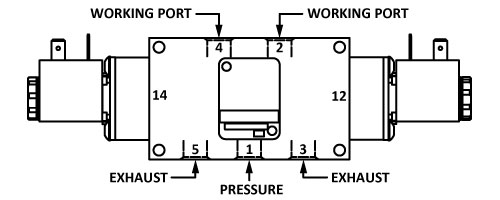
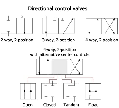
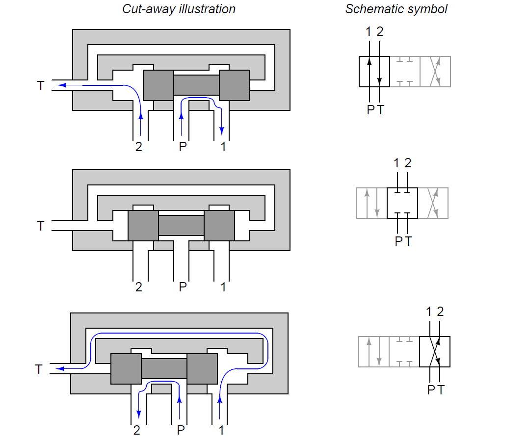
BOOK 2, CHAPTER 8: Directional Control Valves ... Sep 22, 2008 — A 4-way valve pressurizes and exhausts two ports interdependently. A 3-position, 4-way valve stops an actuator or allows it to float. The 4-way ... Solenoid Valve Symbols 4/2 way valve. 4 ports 2 positions. 4/3 way valve. 4 ports 3 positions. 5/2 way valve. 5 ports 2 positions. 5/3 way valve. 5 ports 3 positions. Mechanical valve symbols. ... An engineering line diagram of P and ID will show more detailed and precise information. Get In Touch. Address: Yate, Bristol, UK . Phone:+44 (0)1454 334 990. E-mail ... 4-way Hydrant Valve - Akron Brass Step 1 Attach the 4-Way Hydrant Valve to the hydrant and forward lay to the engine at fire scene. Step 2 Attach a hose from the 4-Way Hydrant Valve to the intake on the engine at the hydrant. Step 3 Attach a hose from the discharge on the engine at hydrant to the 4-Way Hydrant Valve inlet. Establish re-circulating flow at hydrant pressure. PDF Simplified Valve Circuit Guide - Omega Spool Valves, 4-Way, 5-Port The 4-way spool valve can be controlled by using two operators, one on each end or by a spring return and a single operator. The flow path when actuated at the 14 end of the valve is from port 1 to port 4 and from port 2 to port 3. Port 5 is blocked. When the valve is actuated from the 1 2 end, the flow path
Hydraulic Four-Way Valves Oct 27, 2012 — Four-way, directional-control valves are used to control the direction of fluid flow in a hydraulic circuit, which controls the direction of ... a guide to understanding pneumatic directional control valves Circuit consists of a Norgren 4-way valve with a -23 time delay and a shuttle valve. Time Delay on Extension of Cylinder. (Poppet and Spool Valves Shown). The ... Heartland Owners Manuals Anderson 4 way valve Flow Diagram.pdf. 17 May 2018 10:19. 485.7 Kb. Anderson 4 way valve Kantleak RV200 cartridge instructions.pdf. 17 May 2018 10:19. 285.9 Kb. Anderson 4way valve contact and video link.pdf. 17 May 2018 10:19. 10.2 Kb. 4 4-Way/2 and 3 Position Valves 4 and 5-Ported Valves Flow Diagrams De-Energized Press. Cyl. A Cyl. B Exh. Energized Press. Cyl. A Cyl. B Exh. Series General Description Pipe Size (NPT) Page 8340 Air Only 1/4" 83 8342 General Service 1/4" and 3/8" 87 8344 Piston/Poppet 1/4" - 1" 89 8345 General Service 1/4" 93 8401/8402 Slide Valve 1/4" 95 8551/8553 Inline Spool Valve 1/4 ...
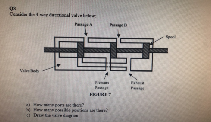
Solved Q8 Consider the 4-way directional valve below Passage ...
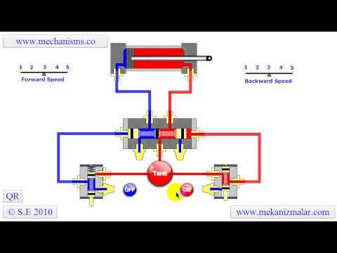
4 WAY 3 POSITION HYDRAULIC CONTROL VALVE WORKING - YouTube In this video we explain 4 way 3 position hydraulic valve working practicallyIn this valve we have four way and 3 position to valve operate We explain all th...

Five-port four-way valve diagram | Download Scientific Diagram
PDF ENGINEERING SYMBOLOGY, PRINTS, AND DRAWINGS Module 2 ... c. Throttled valve d. Combination valves (3- or 4-way valve) e. Locked-closed valve f. Locked-open valve g. Fail-open valve h. Fail-closed valve i. Fail-as-is valve 1.10 Given an engineering P&ID, IDENTIFY components and DETERMINE the flowpath(s) for a given valve lineup. 1.11 IDENTIFY the symbols used on engineering fluid power drawings for the
General Valve Information - AAA Products International
PDF Parker FCD General Purpose 4-Way Valves 4-Way 4/2, 4-Way 2 Position Single Solenoid - Brass* Port Size NPT Orifice Size in. Flow Factor Cv** Operating Pressure Differential (MOPD) PSI Watt Max. Media Temp. °F Seal Pressure Vessel Number Pressure Vessel Number with Metering Pressure Vessel Number with Manual Operator Reference Min. Air, Inert Gas, Water & light oil Coil Valve
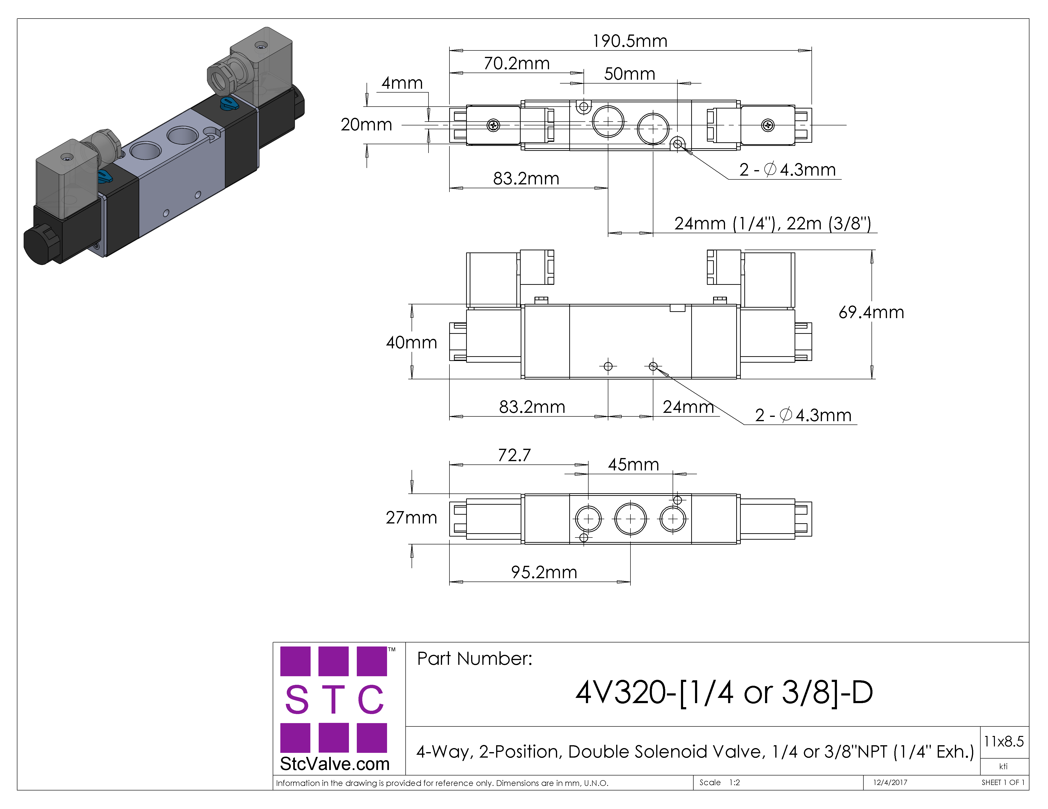
4V320: 4-Way, 2-Position Directional Solenoid Valve
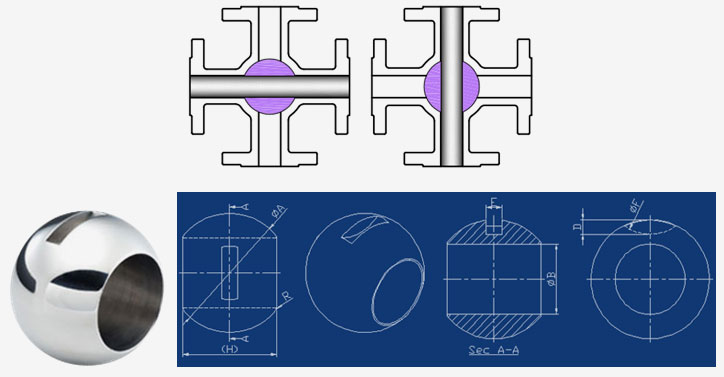
PDF 3 & 4 Way Multiport Ball Valves Standard & Full Port ... 4-WAY: 90ϒ 1 2 P 4-WAY: 270ϒ 1 23 4 Off Position Features Stem Seals Multiport Series 1/ 4"-4" valves all feature a live-loaded stem packing assembly for positive sealing. Utilizing belleville washers, the stem seal automatically adjusts to compensate for changes in temperature and normal wear. The 6"- 12" valves utilize an ...
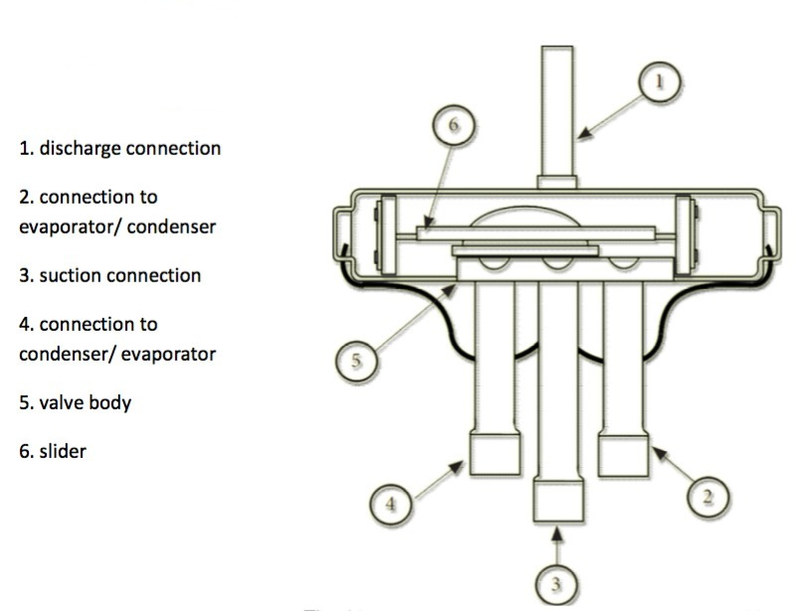
Thermo Fluid Dynamic Design of a 4-Way Reversing Valve
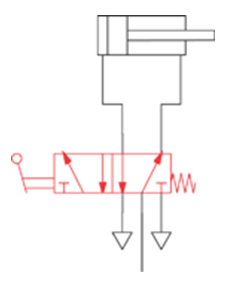
Pneumatic Circuit Symbols Explained - Library ... It has five ports, but it is considered a 4-way valve because two of the ports share the same exhaust function. This is a holdover from hydraulics - where the two exhaust paths are joined (internally to the valve), so that only one return port is required, and only one return line is required to get the hydraulic oil back to the storage tank ...

5/2 & 4/2-Way Pneumatic Valve - How They Work | Tameson.com
4 Way 3 position Control Valve Working ... - YouTube In this lecture you will learn about 1. Spool Type Direction Control Valve.2. Comparison Between Actual Valve & Circuit Symbols.3. Actual Working & Cross sec...

Mac, Val 811CPM-224CA152 4-Way C24VAC | Valves | Parts ...
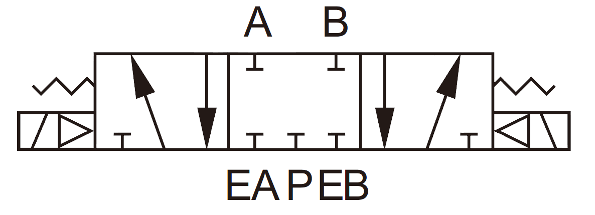
PDF Chapter 5 - Schemes of directional control valves - ISO ... 4/2-way and 5/2-way valves 4/2-way and 5/2-way, as well as 4/3-way and 5/3-way valves are usually used to control double acting actuators. In the example below a manually actuated valve (S1 or S2) controls a double acting cylinder (C1 or C2). Additionally, in order to control the speed of th e cylinder, flow control silencers are in use.
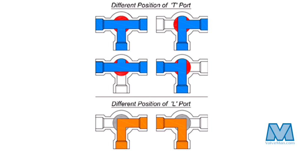
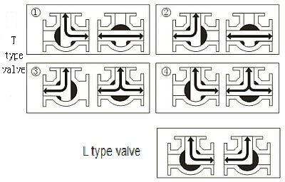
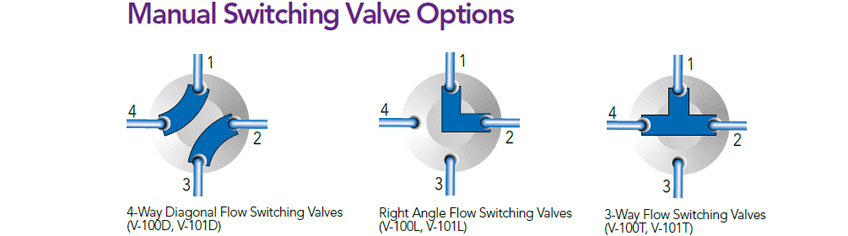
Understanding T-Port vs L-Port Directional Flows - ValveMan.com
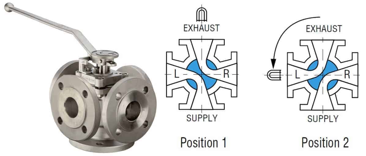
Three-way Ball Valve Flow Patterns | ISM - Industrial Spec An L-pattern flow three-way horizontal version ball valve has two potential shut-off positions. With a four-position valve, these two valve shutoff positions are only 90 degrees or a quarter turn apart. Most horizontal type L pattern flow valves will have handles that are limited to 180 degrees of turn.

4-Way Valve Operation in Blow Out Preventer Accumulator ...
Five-port four-way valve diagram - ResearchGate Download scientific diagram | Five-port four-way valve diagram from publication: Semiempirical model for a hydraulic servo-solenoid valve | High-performance ...

Simulink model of 4-way directional valve. Port S retrieves ...
Working principle diagram of three-way valve - tanghaivalve Three-way valve structure: Three-way valves are generally divided into L-type and T-type. The T-shape can connect three orthogonal pipelines with each other and cut off the third channel, which can split and merge. The L shape can only connect two orthogonal pipes, and cannot maintain the third pipe to communicate with each other at the same time.
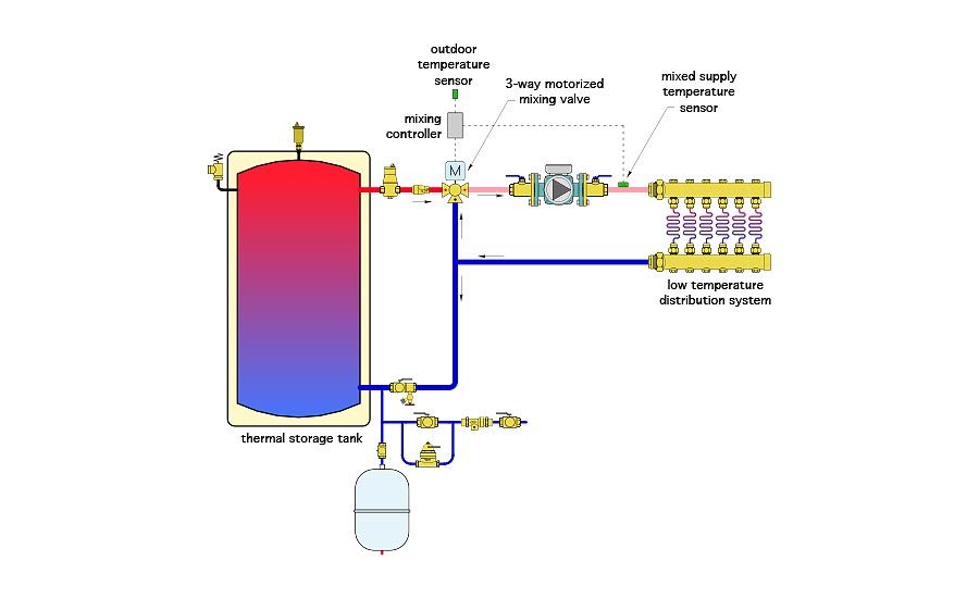
John Siegenthaler: 4-way versus 3-way motorized mixing valves ...
4-Way Reversing Valve Pump diagram and Heat pump schematic ... Sep 28, 2018 · 4-Way Reversing Valve Pump diagram and Heat pump schematic. 4-Way Reversing Valve with operating control used for heat pumps. This is called the 4-Way Reversing Valve, because it has four connections refrigerant pipes. Because the heat pump uses of reversible mechanical refrigeration cycle, such device is not required.

Four Way Directional Control Valves or "Which Way Will the ...
GENERAL VALVE Four-Way Diverter Valve - Schlumberger GENERAL VALVE Four-Way. The GENERAL VALVE Four-Way diverter valve does not rely on line pressure or external hydraulic pressure for positive sealing. The seating elements, or slips, move perpendicularly against the face of the ports. The seals themselves are highly resilient elastomers that are either bonded or mechanically retained in the slips.

4 Way Design Ball Valve Stainless Steel/Brass Manufacturer in ...
Hydraulic Spool Valve Diagram - Valves Spool Diagram Hydraulic Spool Valve Diagram Introduction: E -Type Features: In the neutral position , all oil ports closed, not flow . Functional characteristics: 1. The inlet and outlet ports of device are closed, hydraulic actuator can be fixed in any its' working mechanism position, and no movement or rotary further even if there is external force on it ...

Allen Air | 4 Way 1 4 3 8 1 2 NPT Valves Long Island
PDF Installation, Operation & Maintenance Manual 4-Way ... The M&J 4-Way Diverter Valve is a wide-angle, tapered, lift plug type 4-way valve with raised face flange ends. It is designed to operate with a lift/turn operator mechanism which may consist of a manual handwheel, electric motor, hydraulic motor, or electro-hydraulic (EH) with separate seat/unseat and rotary operators 3. Characteristics
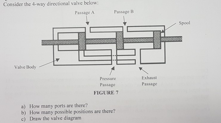
Solved Consider the 4-way directional valve below: Passage A ...
Three Way Valve Diagram - Diagram Sketch Honeywell 3 Port Valve Wiring Diagram Heating Systems Thermostat Wiring Heating Thermostat. Globe Valve Body Design Valve Mechanical Design Design. Calculate Control Valve Position Control Valves Valve Positivity. Flow Tek Multiport 3 Way 4 Way Ball Valve Valve Ball Flow. 1 J 3 H Polosnyj Krossover S Ispolzovaniem Besplatnogo Onlajn Instrumenta ...

Four-way valve - Wikipedia
Four-Way Hydraulic Directional Control Valves | McMaster-Carr Place four-way valves between the pressure source and a double-acting cylinder. In NFPA diagrams, P represents the pressure source, T represents the tank, and A and B represent work ports. For technical drawings and 3-D models, click on a part number. Single-Solenoid Four-Way Valves—2 Flow Positions (4/2 Valves) Single-Solenoid Four-Way Valve 2 3 4

Plug Valves - EnggCyclopedia
GENERAL FOUR-WAY DIVERTER VALVE - Schlumberger The GENERAL Valve 4-Way Operator is a screw jack device designed to provide the necessary mechanical advantage and the “unseat, lift, turn and reseat” motion and seating force required by the GENERAL 4-Way Diverter Valve. Turning the handwheel clockwise causes the plug to lift and retract the seating slips.
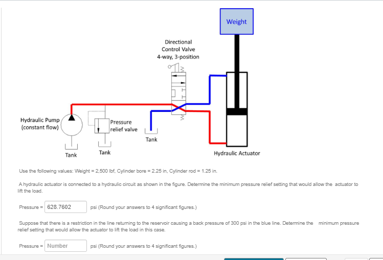
Solved Weight Directional Control Valve 4-way, 3-position ...
4-Way Directional Valve - MathWorks The 4-Way Directional Valve block represents a directional control valve with four ports and three positions, or flow paths. The ports connect to what in a typical model are a hydraulic pump (port P ), a storage tank (port T ), and a double-acting actuator (ports A and B ). Fluid can flow from the pump to the actuator via path P-A or P-B and ...
Grouping and construction of control valves
Working principle diagram of three-way valve - tanghaivalve

Four way valve function in AC

Reversing Valve - Miracle
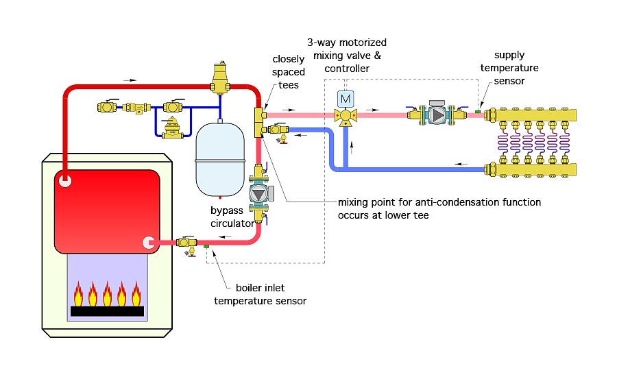
John Siegenthaler: 4-way versus 3-way motorized mixing valves ...
What is Plug Valve? - A Complete Guide for Engineer
Reading fluids circuit diagrams - hydraulic & pneumatic symbols

5/2 & 4/2-Way Pneumatic Valve - How They Work | Tameson.com
503F: Multi-Port 3-Way Ball Valve: 1/4" - 2"
Manual 4-Way PEEK Valves
How five port four way valve works air - air
What is a 4-way Solenoid Valve? - Instrumentation Tools
Solenoid Valve - STC Valve
Four-Way Diverter Valve

Two kinds of four-way valve: (a) traditional three-position ...
Hydrotools, Hydrotools, 4-Way, 3-Position (Tandem Ctr) Valve ...

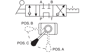
Applications for Cam-Actuated Valves - Womack Machine Supply ...

Four-way Open-center Hydraulic Valve – Hydraulic Schematic ...
Four Way Ball Valve Manufacturer, 4 Way Ball Valve Exporter ...

4/3 way sectional valves type 4/3UREM6 - PONAR S.A. - PDF ...

Heat Pump Reversing Valve
0 Response to "39 4 way valve diagram"
Post a Comment