38 led load resistor wiring diagram
Led Load Resistor Wiring Diagram - Studying Diagrams Led Load Resistor Wiring Diagram 40 A wiring diagram usually gives information not quite the relative point and bargain of devices and terminals upon the devices to incite in building or servicing the device. Led load resistors wiring diagram matstrad for use with led indicator turn signal lights to make them flash at the correct speed can also ... › the-step-down-12-volts-to-68 How to convert 12V to 6V step down circuit diagram Jul 16, 2021 · 1. Limiting current resistor. If you use a load that uses constant current. For example, LED, Light bulbs, relay coil, and more. You can use a resistor in series with these loads. This way is cheapest and so easy. Suppose you have 6V 3W light bulbs. You can use a resistor. How to find resistor level. First, find the current of the light bulbs ...
DIY LED load resistors for trailer with LED lights | Club ... The idea is to make an "extension lead" with this box in the middle, containing the load resistors which are wired in parallel with all of the lighting circuits on the trailer. The service brake wire bypasses the box entirely.

Led load resistor wiring diagram
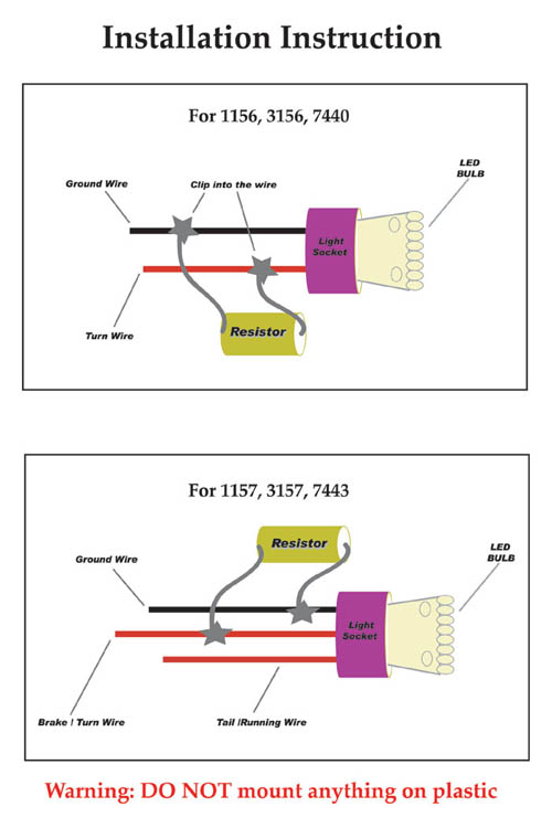
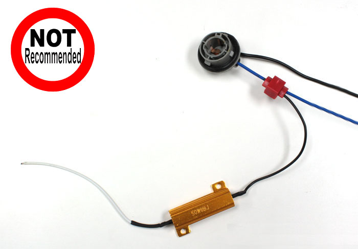
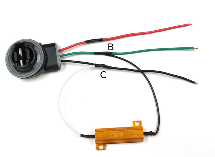
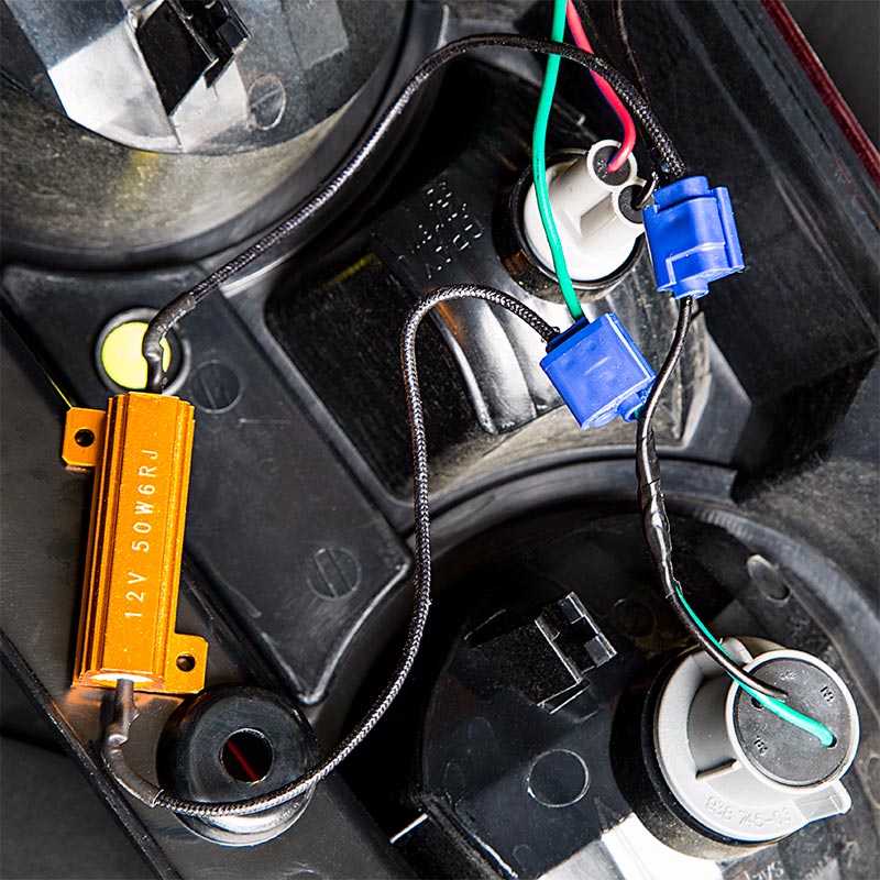
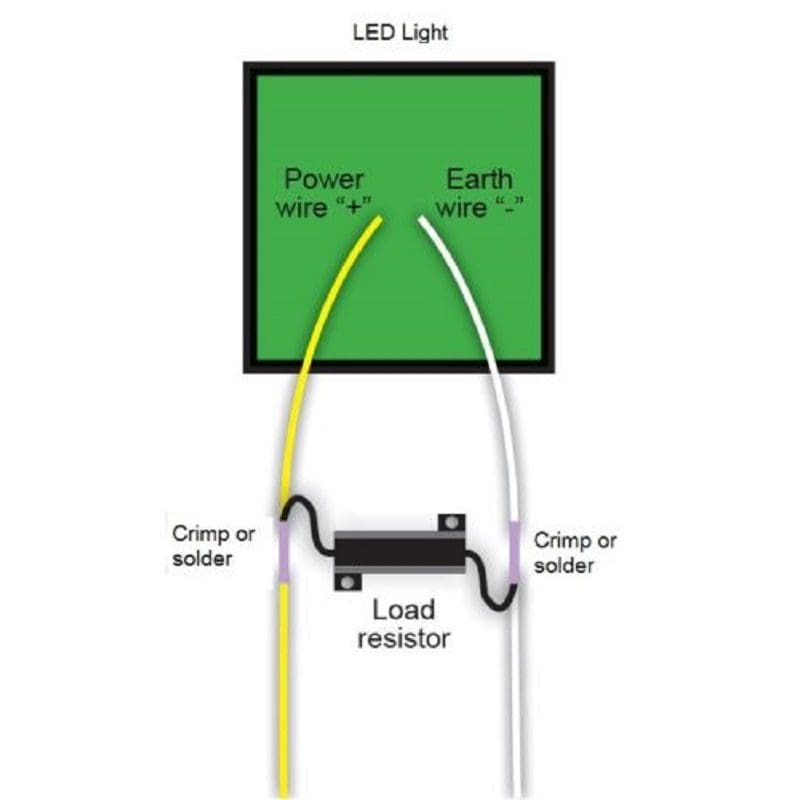
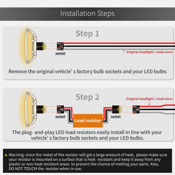
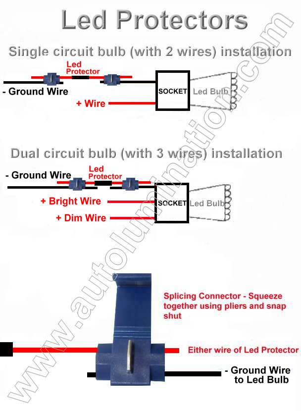
PDF LED Load Resistors INSTALLATION INSTRUCTIONS and the other end of the resistor to the ground wire. See diagram The resistor can be installed in either direction. There is no concern about which end of the resistor is connected to power, and which to ground. Slip the quick connect onto the vehicle's wire first. Next, insert the end of the resistor wire into the quick connect. NOTE! There is no need to strip insulation from the wires. Using pliers, push the quick connect blade down until it is flush with the surface. Turn Signal Light 50W 6-Ohm LED Load Resistor Installation ... Load resistors have no positive or negative sides, so you won't have to worry about which wire goes which side. For single filament applications like the 1156, 3156, 7440, there are only two wires (one positive and one negative). It's pretty straightforward; simply tap the load resistor wires in between these two wires. › 2020 › 06How to Wire a Pilot Light Switch? 2 and 3 Way Wiring The basic type of pilot neon light switch can be wires same as combo of switch and outlet device as shown in fig below. Keep in mind that there is a break a way fin tab (same as in switch/outlet combo) which intact to the line (hot) terminal side i.e. the hot wire can be connected to the single brass (or gold) terminal instead of both terminals.
Led load resistor wiring diagram. Led Load Resistor Wiring Diagram - Wirings Diagram Creative Led Load Resistor Wiring Diagram Details About 4Pcs 50W 6Rj - Led Load Resistor Wiring Diagram. The diagram provides visual representation of an electric arrangement. However, this diagram is a simplified version of the structure. This makes the process of assembling circuit simpler. Led Load Resistor Wiring Diagram - Wiring Diagram Creative Led Load Resistor Wiring Diagram Details About 4Pcs 50W 6Rj - Led Load Resistor Wiring Diagram. Wiring Diagram arrives with numerous easy to adhere to Wiring Diagram Directions. It is meant to help each of the common consumer in developing a suitable method. These instructions will likely be easy to comprehend and apply. › how-to-setup-an-led-matrixHow to Setup an LED Matrix on the Arduino - Circuit Basics Dec 22, 2021 · Follow this wiring diagram to connect a breakout board display to the Arduino: How to Program an LED Matrix on the Arduino Luckily, the programming is the same for LED matrixes wired to the MAX7219 directly and for LED matrix breakout boards. Led Indicator Resistor Wiring Diagram - Wiring Diagram The load resistor has to be connected to the two wires that go to the indicator or tail light bulb holder one end to the postive live wire the other to the negative earth wire. 120 and 240vac led voltage indicator circuit diagram circuit and wiring diagram download for automotive car motorcycle truck audio radio electronic devices home and house appliances published on 13 jul 2014.
› make-interesting555 LED Flasher Circuits (Blinking, Flashing, Fading Effect) Dec 21, 2011 · A very interesting light fading effect can be achieved by wiring up the IC 555 circuit as per the diagram shown below. The circuit switches ON the LED very gradually and does the same while switching it OFF, that is instead of shutting it off abruptly, does it very slowly. Load resistor wiring help for turn signals | Impala Forums But I just looked over diagrams for 13-15 and can't seem to find anything for 12's.. They are Yellow and Red for turn and stop. A wire diagram is good for having a good idea of where to work. Always double check your wire colors with test light. The Load Resistor would go between the Turn Power wire and the Turns ground. It don't go inline James › 2014/12/555-timer555 Timer IC - Types, Construction, Working & Applications In addition, there are three 5kΩ resistors are connected in series with 5kΩ resistor which first end is connected with V CC (Pin 8 = Supply voltage) and the other end is connected with ground (GND = Pin 1). In above fig 1 and (as well as below fig 2 & 3), As given in the block diagram, heart of the IC lies in the two comparator circuits. › article › 78LED Driver Basics and Its Circuit Design Apr 09, 2018 · I LED Driver Basics 1. 1 What is a LED Driver. Led driver changes the power supply to a specific voltage current to drive the LED voltage converter. In general, the input of the LED driver includes the high voltage power frequency AC (i.e., the city electricity), the low voltage DC, the high voltage DC, the low voltage and high-frequency AC (such as the output of the electronic transformer).
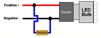
Load Resistors - LED Autolamps - (Pair) - LED AUTOLAMPS LR24/2 Twin blister, 50 Watt 24Ω Ohms. Our LED Autolamp Load Resistors must be mounted on a metal surface, the resistor can reach temperatures of up to 170 Celsius. You may require up to 1 resistor per function on each side. The Load Resistor should always be wired between the input wires of the lamp, not the chassis of the vehicle or trailer! PDF Load Resistor Instructions - PlasmaGlow LOAD RESISTOR INSTALLATION INSTRUCTIONS WARNING: Load Resistors are designed to get HOT! DO NOT Install on/near painted surfaces or plastic! LED Bulb Bulb Socket SPLICE HERE SPLICE HERE GROUND Wire (-) POWER Wire (+) Load Resistor Using the diagram below, splice the Load Resistor's wires in so that it connects ACROSS the positive and Led Resistor Wiring Diagram - Wiring Diagram Practical led indicator and flasher circuits from led load resistor wiring diagram source. Led bulb bulb socket splice here splice here ground wire power wire load resistor using the diagram below splice the load resistors wires in so that it connects across the positive and negative wires of the vehicles turn signal bulb wiring. led load resistor wiring diagram - MaeviRaghad For the LED rocker switch. Each color is wired to its own channel. Sometimes resistor symbols are used in schematic diagrams to designate a non-specific load rather than an actual resistor. The leds are not pulling the same power so the cars smart junction box thinks both bulbs are out and keeps giving me a check left headlamp and.
HELP! LED Load Resistor Install...... | Chevy and GMC Duramax ...
How to Install a Load Resistor for LED Tail Lights - YouTube This video shows which wires you need to connect your load resistor to in order to restore cruise control to your vehicle. This also corrects hyper flash tha...
Резистор для устранения ошибки бортового компьютера при ...
Led Load Resistor Wiring Diagram - Cadician's Blog Creative Led Load Resistor Wiring Diagram Details About 4Pcs 50W 6Rj - Led Load Resistor Wiring Diagram. Wiring Diagram arrives with numerous easy to adhere to Wiring Diagram Directions. It is meant to help each of the common consumer in developing a suitable method. These instructions will likely be easy to comprehend and apply.
Solved!!! Resistors w/ LED installs - Jaguar Forums - Jaguar ...
Simple LED Circuits: Single LED, Series LEDs and Parallel LEDs But as the complexity of the circuit increases, choosing the right resistor with right wattage is important. So, in this project, which is more of a tutorial, we will build some simple LED circuits like a simple single LED Circuit, LEDs in series, LEDs in parallel and high power LEDs.
CAN-BUS или "обманка" — FIAT Linea, 1.3 л., 2007 года на DRIVE2
› 555-time555 Timer Basics - Astable Mode - Circuit Basics Nov 14, 2021 · Larger values will make the LED blink slower, while smaller values will make the LED blink faster. Resistor R3 is just there to limit the current to the LED so it doesn’t burn out. If you want to set the blinking to a certain speed, you can use the formula at the beginning of this article to calculate the resistance or capacitance you need.

Help on Exterior LED Conversion and Load Resistors | Toyota ...
Load Resistor - LED Autolamps You may require up to 1 resistor per function on each side. The resistor should always be wired between the input wires of the lamp, Not the chassis of the vehicle or trailer! If fitted to the chassis, a bad earth connection is possible and can result in problems with the lighting system of the vehicle. Technical Drawings

Flashing Hyper Fix Adapter Resistor Load Light LED 9012 HB4 ...
Adding LED 3157 bulbs + Load Resistors | DODGE RAM FORUM ... Adding LED 3157 bulbs + Load Resistors - Need Help I've looked for wiring diagram on here and im sure someone has said it before but i couldnt find anything with the search feature... Vehicle Information: 2012 Dodge Ram Ext Cab Express 5.7 Hemi Morimoto 50w 6k HIDs Recon Third Brake Light PlasmaGlow led lightbar for under tailgate - Bout to be uninstalled - Worthless *****
daha fazla Işık adlı Paralyze led and resistor connection ...
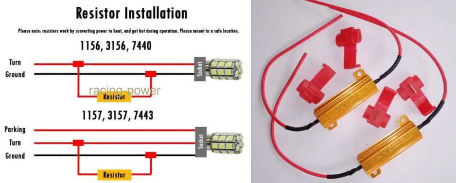
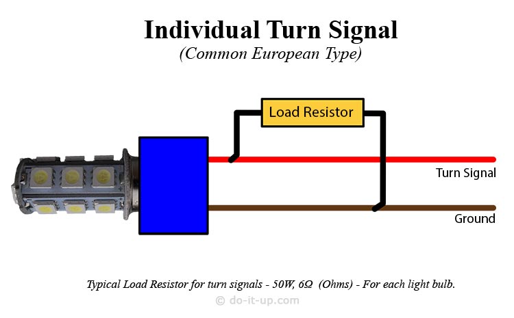
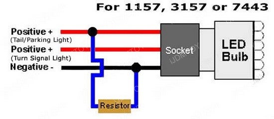
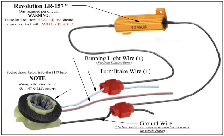
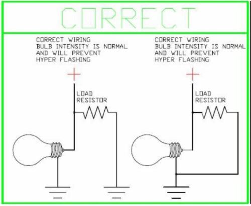
do-it-up.com | » How to Install Load Resistors for LED ... LED Turn Signal Load Resistor Wiring Diagram (Turn Signal Only) LED Turn Signal Load Resistor Wiring Diagram (Stop/Turn Signal) A typical load resistor for a 21 watt turn signal light bulb would have a rating of 50 watts, 6 ohms. Note: This is only an example. So, please check with your supplier, to ensure the correct size is obtained.

Buy KATUR 4pcs 50W 8ohm LED Load Resistors for LED Turn ...
Led Load Resistor Wiring Diagram - Wiring World Creative Led Load Resistor Wiring Diagram Details About 4Pcs 50W 6Rj Led Load Resistor Wiring Diagram. The diagram provides visual representation of an electric. Pin On Elektronika Pin On Avtomobil Connecting Led Strip To 12 Volt Car Battery Power Supply Wiring Diagram Google Search Car Battery Battery Maintenance Led Strip Pin On Schemas Electroniques Simple […]

Qi 4PCS 50W 12ohm 12RJ LED Load Resistor Decoder Fix Hyper ...
Circuit Diagram With Resistor - U Wiring Redraw the circuit diagram with the selected load resistor and be sure to include all voltage polarities and current directions. Any general purpose low power transistor can be. The diagrams below show how to connect an LDR light sensor to a transistor to make a light-sensitive circuit switch on an LED.

Electronic 4Pcs 50W 6ohm Load Resistors Fix LED Bulb Fast Hyper Flash Turn Signal Blink Error Code
Motorcycle Led Indicator Resistor Wiring Diagram Motorcycle Led Indicator Resistor Wiring Diagram- One of the most hard automotive repair tasks that a mechanic or repair shop can endure is the wiring, or rewiring of a car's electrical system. The misfortune in reality is that every car is different. subsequent to exasperating to remove, replace or fix the wiring in an automobile, having an accurate and detailed motorcycle led indicator resistor wiring diagram is valuable to the finishing of the fix job.
Turn Signal Light 50W 6-Ohm LED Load Resistor Installation ...
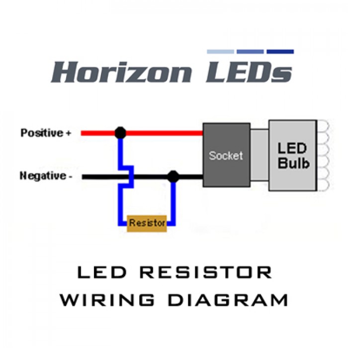
LED Wiring Diagram and Neon Wiring Diagram | Top Forum ... LED Wiring Diagram Notice the load resistor that IS needed. Also notice that the Anode on the LED is connected to positive. The Anode is the LONGER lead. NOTE: If using a light up switch connect the 3rd connection on the switch to ground Similar LED Wiring Diagram Here's a similar LED wiring diagram showing 4 seperate LED's (NOT connected).

2шт H7 LED DRL противотуманные фары Шина CAN 50w 6ohm сопротивление нагрузки проводки компенсатор декодер
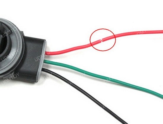
How to Install Load Resistors for LED Turn Signal Lights ... Step 1: 1156, 3156, 7440 are single filament applications so there are only two wires (one positive, one negative). This is very straightforward as you need to simply tap the load resistor wires between the two wires. Ask Question.

Amazon.com: iJDMTOY 50W 6-Ohm Load Resistors LED Turn Signal ...
How to Install a Load Resistor for LED Lights (The Theory ... How to Install a Load Resistor for LED Lights (The Theory, Wiring Diagrams, etc) - YouTube.
randevu Vasıf kapasite led ballast resistor ...
Led Load Resistor Wiring Diagram - easywiring Led load resistor wiring diagram load resistor instructions plasmaglow led productsled bulb bulb socket splice here splice here ground wire power wire load resistor using the diagram below splice the load resistors wires in so that it connects across the positive and negative wires of. Led turn signal load resistor wiring diagram stop turn signal a typical load resistor for a 21 watt turn signal light bulb would have a rating of 50 watts 6 ohms.
How to Install Load Resistors for LED Turn Signal Lights : 6 ...
Led Load Resistor Wiring Diagram - Wiring Diagram led load resistor wiring diagram - You will want an extensive, skilled, and easy to comprehend Wiring Diagram. With this kind of an illustrative guide, you are going to be capable of troubleshoot, stop, and total your tasks without difficulty.

4PCS ARTR 50W 6ohm Load Resistors - Fix LED Bulb Fast Hyper ...
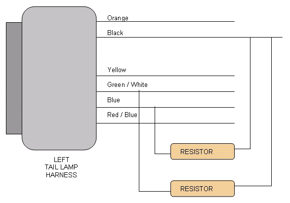
Tail light wiring and LED resistors | Chevy and GMC ... Tail light wiring and LED resistors. Jump to Latest Follow ... Can anyone offer any insight as to which wire or wires need to be connected to the load resistors, or provide a tail light wiring diagram ? Thanks . 2007.5 GMC Sierra 2500HD SLT LMM MBRP Exhaust, Edge Evolution CTS, Beltronics 966ST, AFE Rear Differential Cover, Bilsteins, Hawk pads ...
LED Light Load Resistor Kit - LED Turn Signal Hyper Flash ...
Creative Led Load Resistor Wiring Diagram Details About ... led load resistor wiring diagram - You'll need an extensive, skilled, and easy to know Wiring Diagram. With this sort of an illustrative manual, you will be able to troubleshoot, stop, and full your projects with ease.

Pair T20 W21W 7440 LED Load Resistor Canbus Error Free Wiring ...
› 2020 › 06How to Wire a Pilot Light Switch? 2 and 3 Way Wiring The basic type of pilot neon light switch can be wires same as combo of switch and outlet device as shown in fig below. Keep in mind that there is a break a way fin tab (same as in switch/outlet combo) which intact to the line (hot) terminal side i.e. the hot wire can be connected to the single brass (or gold) terminal instead of both terminals.

Amazon.com: TUINCYN 4pcs 50W 8 ohm LED Load Resistors(DIY ...
Turn Signal Light 50W 6-Ohm LED Load Resistor Installation ... Load resistors have no positive or negative sides, so you won't have to worry about which wire goes which side. For single filament applications like the 1156, 3156, 7440, there are only two wires (one positive and one negative). It's pretty straightforward; simply tap the load resistor wires in between these two wires.

Amazon.com: Zone Tech 50W 6 Ohm LED Load Resistors - 8-Pieces ...
PDF LED Load Resistors INSTALLATION INSTRUCTIONS and the other end of the resistor to the ground wire. See diagram The resistor can be installed in either direction. There is no concern about which end of the resistor is connected to power, and which to ground. Slip the quick connect onto the vehicle's wire first. Next, insert the end of the resistor wire into the quick connect. NOTE! There is no need to strip insulation from the wires. Using pliers, push the quick connect blade down until it is flush with the surface.

randevu Vasıf kapasite led ballast resistor ...

How to Install a Load Resistor for LED Tail Lights - YouTube

Buy KATUR 4pcs 50W 8ohm LED Load Resistors for LED Turn ...

Do I have this correct - Dodge Ram xBA Turn Signals ...
Load Resistors

Buy Malayas 4Pcs/Pack Car 50W 6OHM Load Resistors - Fix LED ...
12v LED lights load resistor
How to Install Load Resistors for LED Turn Signal Lights : 6 ...
Load Resistor - Decoder for LED Headlight Bulbs - 9007 HB5

how to wire in load resistor? | Page 2 | Yamaha Starbike Forum

RESISTOR INSTALL GUIDE
Help installing LED turnsignal bulbs - Ford F150 Forum ...
Help with LED load resistors / protectors - RX8Club.com
50W LED CANBUS FREE - LOAD RESISTOR KIT

How To Install LED Resistors - Everything You Need To Know | Headlight Revolution
Load Resistor Kit for LED Turn Signals - 50 Watts - 6 Ohm ...

Amazon.com: TUINCYN 4pcs 50W 8 ohm LED Load Resistors(DIY ...
Do LED Turn Signals Need Load Resistors When Installed on a ...
0 Response to "38 led load resistor wiring diagram"
Post a Comment