39 pto switch wiring diagram
John Deere Stx38 Pto Switch Wiring Diagram. I turned the engine off and on and repeated with the PTO switch .. not give any information about tractor wiring or tractor wiring diagrams. Looking at the diagram from John Deere, It looks like the wiring plugs in with three (3) connectors. The PTO Switch is #17 and the Plugs are #2. I did one mod using a 3DPDT mini-switch from [guitarelectronics.com](https://guitarelectronics.com) and it went fine, but it was only because I literally found a diagram on their site that told me EXACTLY what to wire to what lug. I've got an idea for another mod and I'm trying to figure out what type of switch I need and what to wire to what. For example, this diagram for a single pole on/on switch I believe makes sense to me: ​ https://preview.redd.it/rl6c19tcppf81.png?width=1280&...
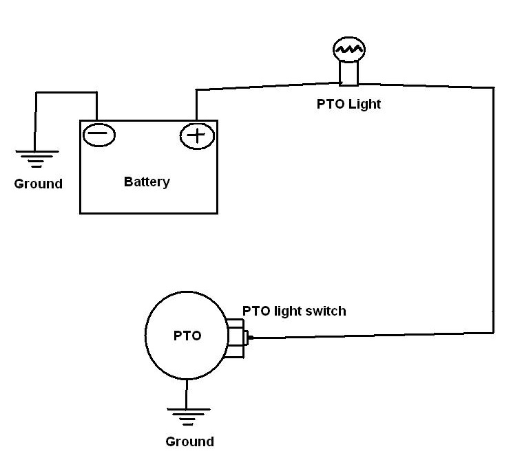
A wiring diagram is a streamlined conventional photographic representation of an electric circuit. The pto is the mechanism that turns on the blades located under the mower deck. When the lawn mower is running and the switch on the dashboard is engaged to the on position the blades will start to turn. The electric clutch is operated by a switch ...

Pto switch wiring diagram
Muncie Pto Pressure Switch Wiring Diagram Release PTO Switch. .. Wiring Diagram: Standard "H" Shift Option Model Years Standard.Muncie Power Products is a leading manufacturer of power take-offs (PTO), hydraulic components such as pumps, motors, cylinders, valves and reservoirs, and snow & ice removal products. A wiring diagram is a simplified conventional pictorial representation of an electrical circuit. 1000 cub cadet pto wiring diagram wiring diagram cub cadet pto switch wiring diagram. Three wire cable runs between the switches and the outlet. John deere gator 4×2 wiring diagram best. Be sure to route away from moving. 6205-131C. Universal. 1.4" Diameter. Yellow. Yes. Basic PTO. Delta's standard unsealed PTO switches control switching for two independent circuits. This rugged and ergonomic design is a simple and cost-effective snap-in installation. They are fully customizable by knob/knob colors and graphics offerings.
Pto switch wiring diagram. Pto Switch Wiring Diagram - chelsea pto switch wiring diagram, craftsman pto switch wiring diagram, electric pto switch wiring diagram, Every electrical arrangement is composed of various different parts. Each component ought to be set and connected with different parts in particular manner. Otherwise, the arrangement won't function as it ought to be. Wiring Diagrams See figure 8 for PTO 15/12 See figure 9 for PTO 30/25 See figures 10 and 10A for all other PTOs Typical Installation See figures 5, 6 and 7 for all models. Shaft Installation See figure 11 for all models. It is strongly recommended to keep the angle of the shaft within 10 degrees from the tractor PTO and generator gear box. The PTO is the mechanism that turns on the blades located under the mower deck. The PTO works off of a 12-volt system. The electric clutch is operated by a switch located on the dashboard of the lawn mower. When the lawn mower is running and the switch on the dashboard is engaged to the "on" position, the blades will start to turn. to insure the correct wiring harness and these instructions. (For models prior to 2013 follow the instructions for the "B" shift code found in kit 48TK5082.) The 2013 and later chassis are provided with a PTO switch on the dash panel located with the other auxiliary switches.
I’d like to wire one of my guitars with 2 humbuckers with a volume and tone for each, a 3 way pickup selector switch, a 2 way switch to go out of phase, and a 2 way switch to split the coils. Like the wiring on the frank zappa Roxy SG. I'm replacing a standard light switch with a smart one. The wiring diagram confuses me. Neutral goes to N, and to the plant which is presumably earth, and to L1? I'm completely flummoxed. I'd have thought Neutral to N, permanent live L, switched live L1, earth to? Anywhere? Anywhere here's the diagram, appreciate any help. [https://imgur.com/a/bsSvfpb](https://imgur.com/a/bsSvfpb) FWIW, the earth(s) are not currently fixed to the back of the metal junction box. Dimension: 214 x 300. DOWNLOAD. Wiring Diagram Images Detail: Name: craftsman pto switch wiring diagram - Craftsman Riding Mower Electrical Diagram Wiring Within Lawn Ignition Switch. File Type: JPG. Source: originalstylophone.com. Size: 237.52 KB. must be out, and the PTO switch must be off. 2. With the engine running and the opera-tor off the seat, the engine will die if either steering lever is brought in or the PTO switch is turned on. 3. The engine will also die if the operator gets off the seat with either steering lever in or the PTO switch turned on. 4.
See my other video on this as well. As before, do this at your own risk to your machine and yourself. These instructions are intended to be used as a tempora... In this video you'll learn how an electric pto switch works and how to test them. These switches come on your riding mowers with electric clutches, as well a... on John Deere L130 Pto Wiring Diagram. I have a john deere L and the mower deck will not engage. I If there is no power here then check the two yellow wires at the pto switch Looking at the schematic there are two splices that the yellow wire runs through. John Deere Lawn Tractor Wiring Diagram Fresh John Deere L Pto Wiring Diagram Download ... DOWNLOAD. Wiring Diagram Sheets Detail: Name: pto switch wiring diagram - 3 Speed Switch Wiring Diagram Unique Pto Switch Wiring Diagram 45 Impressive 3 Speed Switch. File Type: JPG. Source: bestcartierlovebracelet.com. Size: 64.26 KB. Dimension: 1004 x 698. DOWNLOAD. Wiring Diagram Images Detail:
PTO OEM Freightliner M2 - Verizonconnect-installer
1000 Cub Cadet Pto Wiring Diagram | Wiring Diagram - Cub Cadet Pto Switch Wiring Diagram. Wiring Diagram consists of numerous detailed illustrations that display the link of assorted items. It consists of instructions and diagrams for different kinds of wiring methods and other products like lights, windows, and so forth.
318 pto switch | Weekend Freedom Machines
This switch controls one single outlet (which shows 20V when the switch is off - phantom voltage? safe for a power strip + computer to be plugged into?). The (plastic) box has FOUR different NM cables (I think I'm using the right terminology) - 3 are white/black/bare and one is white/black/red/bare. The switch was mounted upside-down, which I understood once I saw the sheer amount of wires shoved behind it. Pics below but I think the lovely MSPaint wiring diagram makes it easier to see what's...

Rotary Pto Switch For Scag 13248 | Griggs Mower Parts
I have some ditch lights that I installed that I'd like to come on with the high beams as well as a switch that I installed. I know how to do the wiring on that side, but what I'm not sure is which wire I need to tap into (I'll try to connect the wire into the harness, rather than literally tapping the wire) for the high beam signal. ​ I am thinking that my easiest option to accomplish this is from the wires that come from the multifunction switch. I have searched for any indicatio...

New Holland TT60 TT75A Repair Manual Tractors – eRepairInfo.com
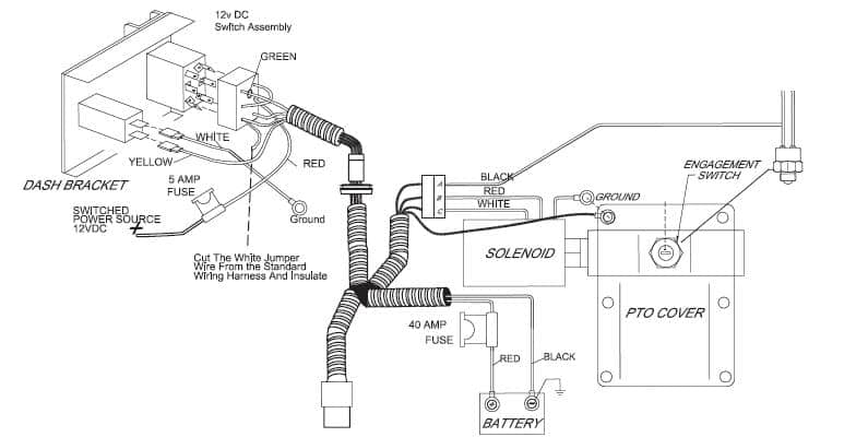
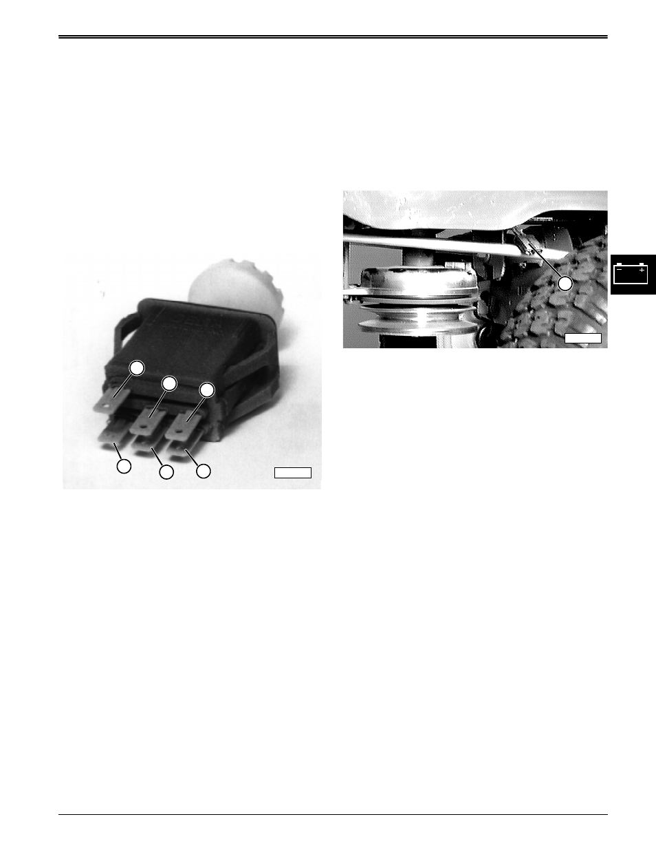
wiring diagram. The green wire in back of connector is up. Connect the power wire to a 12V keyed accessory power source. Modification of wire harness is NOT recommended. Notify Customer Service if modifications are required. 7. Route the 3-wire plug down to the PTO and connect to the solenoid 3-wire plug. Be sure to route away from moving ...
GT5000 PTO conked out after brain fart | Garden Tractor Forums
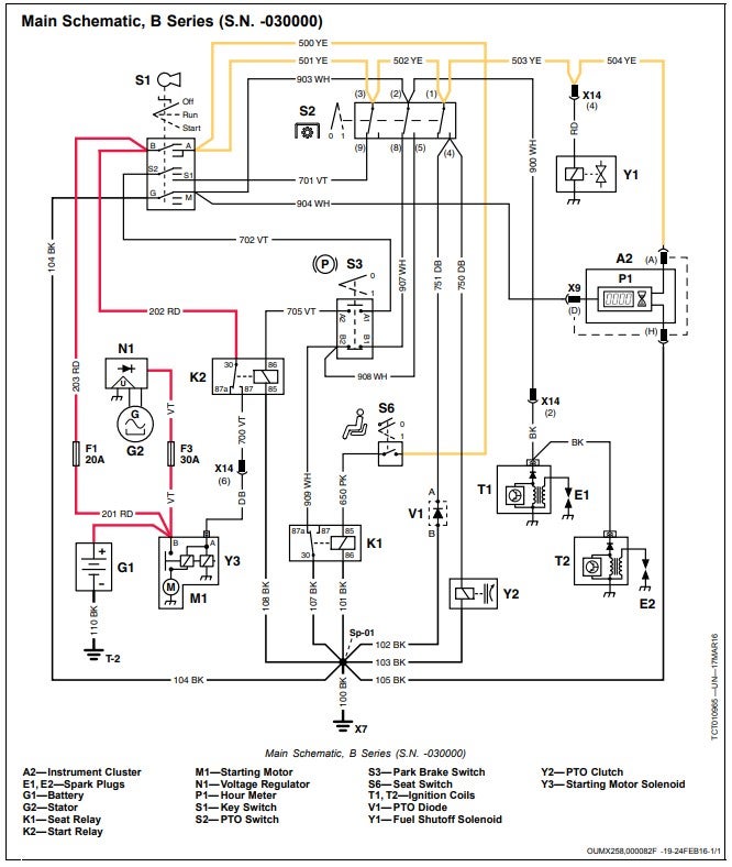
•1993—1995 with S.N.'s 120001—150000 have a park lock switch added. •1995—1996 with S.N.'s 150001—150081 have a wiring harness with integrated diodes and a new PTO actuation system. •1995—1996 with S.N.'s starting at 150082— have a wiring harness with a diode pack and a new PTO actuation system. F915
Troubleshooting PTO Installation: Working Through the Bugs ...
https://imgur.com/a/SjptUCx I currently have a single router blasting wifi to the whole house, but since its all wired, I'd like to upgrade to wired backhaul mesh points. I know that if I simply plug the mesh points into the outlets then I'll run into a "downstream" problem, where the mesh points aren't downstream from the router. What I don't understand is where the switch needs to go in this diagram so that I won't have that downstream problem.

John Deere Push Pull PTO Switch Kit - AM118804
The briggs was manual PTO and the Walk behind was electric, so I just switch the pulleys from 1 to the other, Anyways there are 2 wires coming out of the PTO and the PTO switch has 5 wires coming out of it. Im assuming 2 going to the stator, 2 to the PTO and a ground.
How to Install HINO PTO Interface for HINO with Allison ...
pto switch wiring diagram - You will need an extensive, skilled, and easy to understand Wiring Diagram. With this sort of an illustrative manual, you are going to be capable of troubleshoot, prevent, and complete your projects without difficulty.

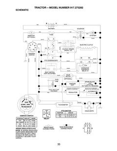
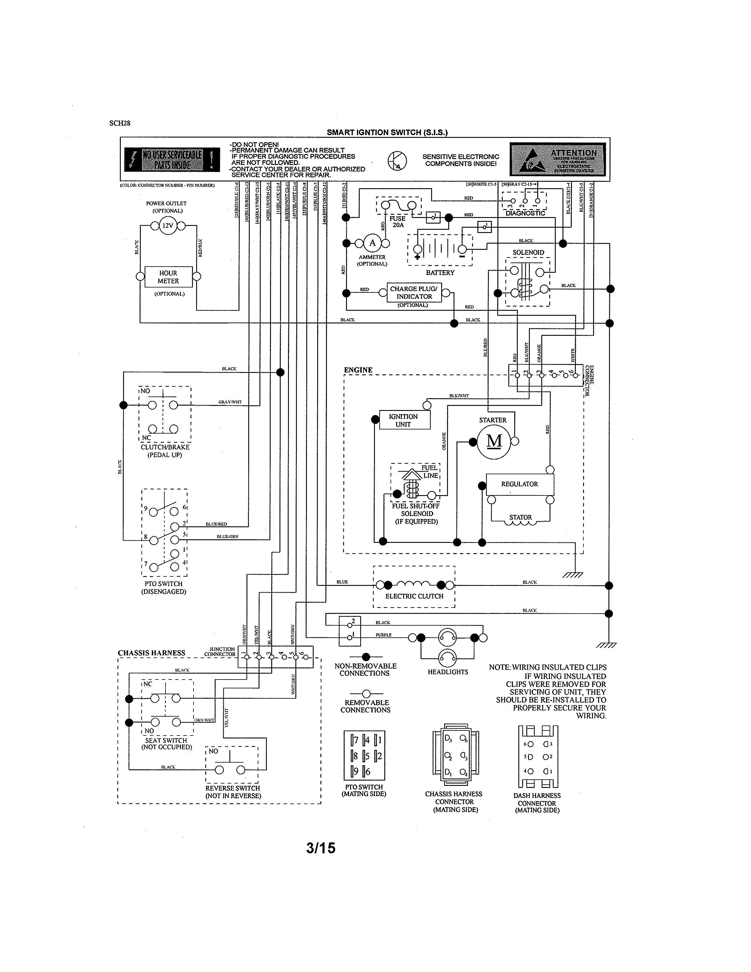
Husqvarna YTH2148 SCHEMATIC
Pto Switch Wiring Diagram - chelsea pto switch wiring diagram, craftsman pto switch wiring diagram, electric pto switch wiring diagram, Every electric arrangement is composed of various unique pieces. Each part ought to be set and connected with different parts in particular way. If not, the structure won't function as it should be.
I'm Going To Stop Hanging Out Here On The Zero Turn Forum ...
The electric PTO clutch on a John Deere L runs a volt system and controls Plug the connector from the wiring harness into the right side of the clutch. john deere L lawn tractor wiring diagram for safety switches Hope this helps some. L John Deere PTO problems I was mowing and deck stopped. My JD L just experienced the infamous PTO anti ...
430 PTO wiring | Green Tractor Talk
2021 UPFITTER SCHEMATIC 2500/3500 PICKUP BOX ON With AUX switches (LHL) A M H B C F D J A Aux PDC (auxiliary Power Distribution Center-relay/fuse box) Underhood B C D J H 2 Upfitter Connectors (Light and Dark Gray) PDC (main Power Distribution Center-relay/fuse box) underhood
Snapper Pro 5900504 - S200XTBV32, Zero-Turn Rider Parts ...
John deere l120 pto switch wiring diagram I have a John Deere L120 with about 280 hours on it. Today while I was mowing my lawn the mower just stopped dead. I lost all electrical power. It turned out that my 20 amp fuse blew out. I bought a new fuse and tried to replace it and it shorted out immediately while I was trying to put it in.
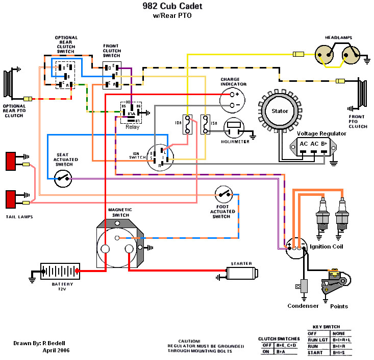
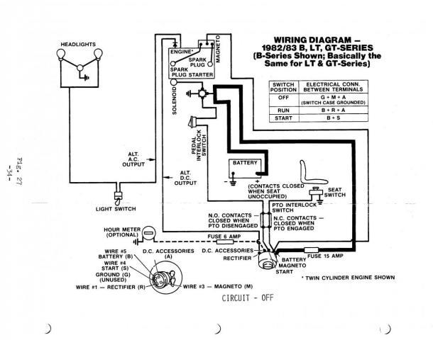
Wiring Diagram - 82 Series - Only Cub Cadets
Not working and don't know if it's because I'm over thinking or under thinking problem. Here's a picture of the box: https://imgur.com/1ATbgsX Here's what I've tried to understand (a diagram): https://imgur.com/a/X4XG8aS Here's the instructions from the switch: https://imgur.com/vE3aUIF Here's the switch I'm trying to wire: https://www.amazon.com/gp/product/B00H3QQD64/ref=ppx_yo_dt_b_asin_title_o03_s01?ie=UTF8&psc=1 Could really use some help untangling this!
Pto switch tests, Pto clutch test | John Deere stx38 User ...
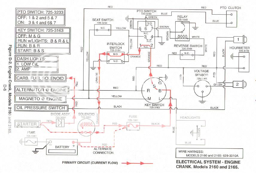
'PTO' Switch on This wire goes to ground when the temp gauge needle gets into the red. +12 volts with key in the 'RUN' position High Temp Relay - Clutch Circuit To Universal Harness This is a ground wire E To Relay D To Universal Harness To PTO Green Switch Brown Brown Brown +12 volts with 'PTO' Switch on +12 volts with 'PTO ...
DGT 6000 Wiring Issue
Looking at the diagram from John Deere, It looks like the wiring plugs in with three (3) connectors. The PTO Switch is #17 and the Plugs are #2. John Deere Lawn Mowers If you have a wiring diagram that show the wiring of the PTO then maybe I can trace it back and see where the grounds are set up at.Top Rated Plus.

I'm Going To Stop Hanging Out Here On The Zero Turn Forum ...
Checked the PTO Here is the wiring schematic for the L graphic.Apr 29, · I'm trying to find a wiring diagram for a John Deere L riding mower. The starter won't make any noise at all, not even the starter solenoid. The battery is charged. PTO switch (or PTO safety switch) brake switch Starter solenoid trigger wire. The JD tech manual is .

Small Engines - » Basic Tractor wiring diagram
Power Take-Off (PTO) - Two Inputs, One Output Only Once Relay Wiring Diagram. The relay on the left is the control relay for the PTO. 30 on the first relay is your input. 87 on the first relay is your output to allow the PTO to operate. The second relay from the left allows the negative output from the neutral switch to pass to the coils of the ...
John Deere 111 - PTO Does Not Engage | My Tractor Forum
April 12, 2020. · Wiring Diagram. by Anna R. Higginbotham. cub cadet pto switch wiring diagram - You will want a comprehensive, expert, and easy to understand Wiring Diagram. With this sort of an illustrative guide, you will be capable of troubleshoot, prevent, and complete your tasks without difficulty.
PTO Interlock Stop Switch - Wheel Horse Electrical ...
(If this is not the appropriate subreddit, I apologize) https://res.cloudinary.com/phostenix/image/upload/GuitarWiring/Strat9-Way4.jpg (Link of said wiring diagram) Converting the wiring of my strat so I can have some different options. Searched through google and tried learning more wiring on my own the past week but, I am horribly confused still. I would greatly appreciate any advice on how I could do this. Thank you! P.S.- Also, anyone know someone I could pay to make a custom wiring di...
Electric Pto wiring diagram | My Tractor Forum
6205-131C. Universal. 1.4" Diameter. Yellow. Yes. Basic PTO. Delta's standard unsealed PTO switches control switching for two independent circuits. This rugged and ergonomic design is a simple and cost-effective snap-in installation. They are fully customizable by knob/knob colors and graphics offerings.

12+ Electric Clutch Wiring Diagramelectric clutch wiring ...
A wiring diagram is a simplified conventional pictorial representation of an electrical circuit. 1000 cub cadet pto wiring diagram wiring diagram cub cadet pto switch wiring diagram. Three wire cable runs between the switches and the outlet. John deere gator 4×2 wiring diagram best. Be sure to route away from moving.
PTO Interlock Stop Switch - Wheel Horse Electrical ...
Muncie Pto Pressure Switch Wiring Diagram Release PTO Switch. .. Wiring Diagram: Standard "H" Shift Option Model Years Standard.Muncie Power Products is a leading manufacturer of power take-offs (PTO), hydraulic components such as pumps, motors, cylinders, valves and reservoirs, and snow & ice removal products.
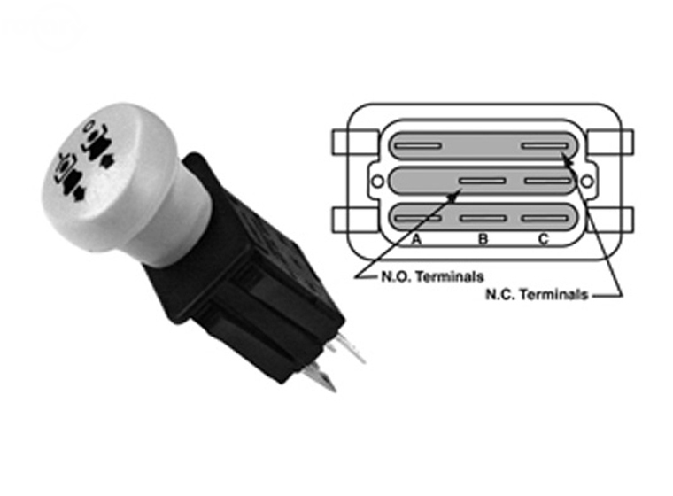
PTO SWITCH CONNECTOR

Crazy L130 problem | Tractor Forum

I need to replace the pto switch on my Simplicity lawn ...
Safety switches won't work on my 216 | Tractor Forum

Pin on DIY
04-05 Demyst.book
Professional Power Equipment Technicians & Education Network ...
580 PTO wiring | IH Cub Cadet Tractor Forum
318 pto switch | Weekend Freedom Machines

SOLVED: How do i fix a LA 145 john deere pto clutch - Fixya
Layout 2

I'm Going To Stop Hanging Out Here On The Zero Turn Forum ...
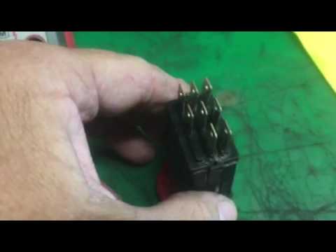
Testing a PTO switch

Bezares SA - Leading hydraulic manufacturer
Troubleshooting Article Archive

SWZ hydro drive walk behind color wiring diagram - SCAGTech
Cub cadet 2160 ground wire issue - TractorByNet
0 Response to "39 pto switch wiring diagram"
Post a Comment