39 3 Phase Converter Wiring Diagram
How to Convert Three-Phase to a Single-Phase | Hunker To convert 3-phase to single-phase power, you can use a phase converter. This device can be wired to the motor you plan to run that requires single-phase power. Note that this will impact only the device wired to it, not an entire outlet because it is not hardwired into your electrical system. Run two wires from the motor to the converter. Schematic Wiring Diagram March 29, 2021 Add Comment 1 pole contactor wiring diagram, 2 pole contactor wiring diagram, 3 pole contactor wiring diagram, 4 pole contactor wiring diagram, double pole contactor wiring diagram, schneider 4 pole contactor wiring diagram, single pole contactor wiring diagram, two pole contactor wiring diagram Edit
DIY Solar Wiring Diagrams for Campers, Vans & RVs ... 24V - 6000W - 120V/240V Split Phase Camper Solar Wiring Diagram This diagram is for users requiring extensive power demands through 120V/240V split phase at up to 3000w per leg. This diagram also shows how to wire multiple solar arrays through multiple charge controllers into the Lynx Distributor.

3 phase converter wiring diagram
Need wiring advice from RPC to 3-phase sub-panel. Problems ... I am feeding a 3 phase sub-panel with T1, T2, and T3 from my American Rotary AD20. Wiring 1 machine at a time directly to the phase converter works just fine but when I wire the phase converter to the 3-phase panel and turn on the breakers, the start/stop switch on my 3hp grinder is buzzing, with the phase converter OFF. Wiring Diagram 240 To 480 Phase Transformer 3 [Z7YMDF] Dimensions (Inches) Approx Ford Escort 1991-1999 Wiring Diagram potential transformers three phase three wire potential transformer 2vt469 connection diagram 240:120 277:120 288:120 300:120 *480:120 *600:120 1 The three-phase power is connected in the delta configuration, and the center point of one phase is grounded Table 2: 480 V Delta Primary to 208Y/120 V Secondary kVA Part Number ... wiringdiagram.2bitboer.com › single-phase-to-3Single Phase To 3 Converter Wiring Diagram - Wiring Diagram Dec 01, 2017 · How Is Three Phase Converted To Single Quora. Single phase to three converter ac circuit convert 3 inverter diagram rotary conversion system how does a static work balancing output voltage of building powering electrical devices motor running on build vfd power supply converted converting auto start wire apply 5 hp 1 gohz com wiring simple converters 101 learn they welder startup procedure ...
3 phase converter wiring diagram. 3 Phase Transformer Wiring - Diagram Sketch Three Phase Transformer Connections And Basics In 2021 Current Transformer Transformers Transformer Wiring. 3 Phase To 1 Phase Wiring Diagram In 2021 Electrical Diagram Electrical Circuit Diagram Diagram. Single Phase Wiring Diagram For House Electrical Wiring Colours Electrical Wiring Diagram Electrical Electrical Wiring Electrical Panel ... autocardesign.org › single-phase-to-3-phaseSingle Phase to 3 Phase Converter Wiring Diagram - autocardesign Jun 26, 2019 · Single Phase to 3 Phase Converter Wiring Diagram– wiring diagram is a simplified welcome pictorial representation of an electrical circuit.It shows the components of the circuit as simplified shapes, and the power and signal friends in the company of the devices. Our Comprehensive Guide To Enerdrive DC To DC Charger Wiring: Enerdrive have released three pre-wired charging cables to connect to the DC to DC charger that is mounted in these systems. We've created three simple DC to DC charger wiring diagrams to make your buying decision seamless! Step One: Decide where you are planning on mounting the DC to DC Charger. Either in your drive vehicle or in the caravan ... Single-Phase or Three-Phase Input Power for Rack PDUs ... With three 208V circuits it is clear that a substantial amount of power can be deployed in one three-phase PDU. To calculate the apparent power of a three-phase power feed the calculation is volts x amps x the square root of 3 which is 1.732. A three-phase 208V, 20A feed is 7205VA or 7.2kVA (208V x 20A x 1.732).
3 Phase Rotary Switch Diagram - easywiring Wiring diagram for loads that american rotary total up to 3 phase idler motor t1 t2 t3 wiring diagram for paralleling multiple phase converters using a transfer switch note all wiring must be done by a licensed phase a matic inc rotary phase converter installation 230v r series rotary converter is 230v single phase in single unit installation ... Jet GHB-1440a reversing switch wiring According to the motor wiring diagram the motor is wired for CW rotation @220v. I did confirm this is how it's running last night. That is T3 T2 and T8 connected together with a 110v leg going to T1 and the other leg going to T4 and T5. Interactive Wiring Diagram For Camper Van, Skoolie, RV ... Here is an interactive version of our wiring diagram for camper van, skoolie, RV, etc. ... Samlex SEC-1230UL 50A Battery Charger/Converter 120V AC Wall Outlet Power Cord Samlex PST-1000-12 1500W Pure Sine Inverter How to Install Shore Power in a Campervan Electrical System The wiring diagram below is for a 110v AC supply including a double pole RCD breaker, at least one switched socket for AC appliances and a circuit to the battery charger / power converter. Any DC appliances can continue to run as the battery bank is charging. It is identical to the 240v wiring diagram above but the wire colours follow the US ...
Wiring Diagram | Trailer | USB | Nest Diagrams 3 phase motor wiring diagram 6 wire - You'll need an extensive, expert, and easy to know Wiring Diagram. With this kind of an illustrative guidebook, you'll be able to troubleshoot, prevent, and total your tasks with ease. Not just will it assist you to… Lymphatic Drainage Diagram - 3 phase converter wiring ... Lymphatic Drainage Diagram - 9 images - lymphatic system marsha g clarke rmt, human body systems overview anatomy functions kenhub, Contactor 3 Phase Wiring Diagram - The Wiring 3-Phase, Size 6 45 3-Phase, Size 7 46 3-Phase Additions and Special Features 47-50. Start stop 3 wire control. AC Blower Motor Wiring Diagram furthermore 3 Phase Star Full-voltage non-reversing 3-phase motors. Contactor 3 phase wiring diagram. Starting a three phase motor. A wiring diagram is a simplified traditional pictorial depiction of an electric circuit. […] PDF INSPECTION INSTALLATION AVOIDING ... - ARCO Electric Wire size will be determined from the INPUT CHART for the Roto-Phase converter. (SEE INSTALLATION DIAGRAM) Consult the wire size chart for the converter model being installed. The first 2-pole breaker will be rated at 125% of the recommended fuse protection of the phase converter. The two single-phase circuits L1 and L2 from this breaker
44 Phase Converter ideas | electrical circuit diagram ...
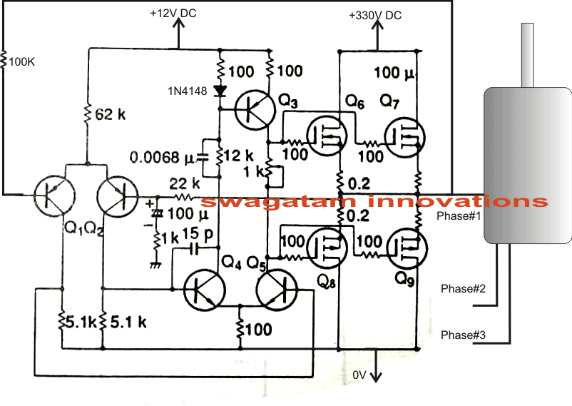
How to Make a 3 Phase VFD Circuit - Homemade Circuit Projects Configuring the 3-Phase Generator Circuit. The 3 phase generator is constructed around a couple of CMOS chips CD4035 and CD4009 which generates accurately dimensioned 3 phase signals across the shown pinouts. The frequency of the 3 phase signals depends on the fed input clocks which should be 6 times the intended 3 phase signal.
44 Phase Converter ideas | electrical circuit diagram ...
3 Phase Wiring Diagram - U Wiring Single Phase to 3 Phase Converter Wiring Diagram wiring diagram is a simplified welcome pictorial representation of an electrical circuit. Phase 1 L2 L4. Three Phase Distribution DB box Connectionwhat is a three phase lineIn electrical engineering three phase electric power systems have at least.

Phase converter - Wikipedia
frequency converter 50hz to 60hz 3 phase frequency converter 50hz to 60hz 3 phase ORDER BY PHONE 2019 form 1040 schedule 1 instructions Mon to Fri: 9am - 5pm (EST) Service en Francais par Telephone Be Canadian, buy Canadian.

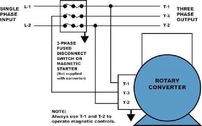
How to Wire a Rotary Phase Converter - Electric Problems
220 Volt Plug Receptacles Configurations - AskmeDIY For the most part, you are going to see 120 volts, 15 amp, and 20 amp. And 220 2 wire, 3 wire, and four wire types. Please remember not all 220-volt outlets use a neutral (white) wire. To give you a general idea, let's say you just bought an air compressor from Home Depot. It requires 220 volts but the plug only has three prongs.
How to Build a Rotary Phase Converter - HomemadeTools.net
220v Single Phase Wiring Diagram - The Wiring 3 Phase Motor Wiring Diagrams Electrical Info PICS Non . Wiring Diagram For 220 Volt Single Phase Motor . 220v single phase wiring diagram 32 wiring diagram Wire . Din rail energy meter 5(30)A 50HZ 220V 230V Watt hour . This triacbased 220V AC motor speed controller circuit is .
Balancing Output Voltage of Rotary Converter
Single Phase Motor Wiring Diagram With Capacitor Single Phase Motor Wiring Diagram With Capacitor - baldor single phase motor wiring diagram with capacitor, single phase fan motor wiring diagram with capacitor, single phase motor connection diagram with capacitor, Every electrical arrangement is made up of various unique pieces. Each component ought to be placed and linked to different parts in particular manner.
How to convert the single phase to three phase - Quora
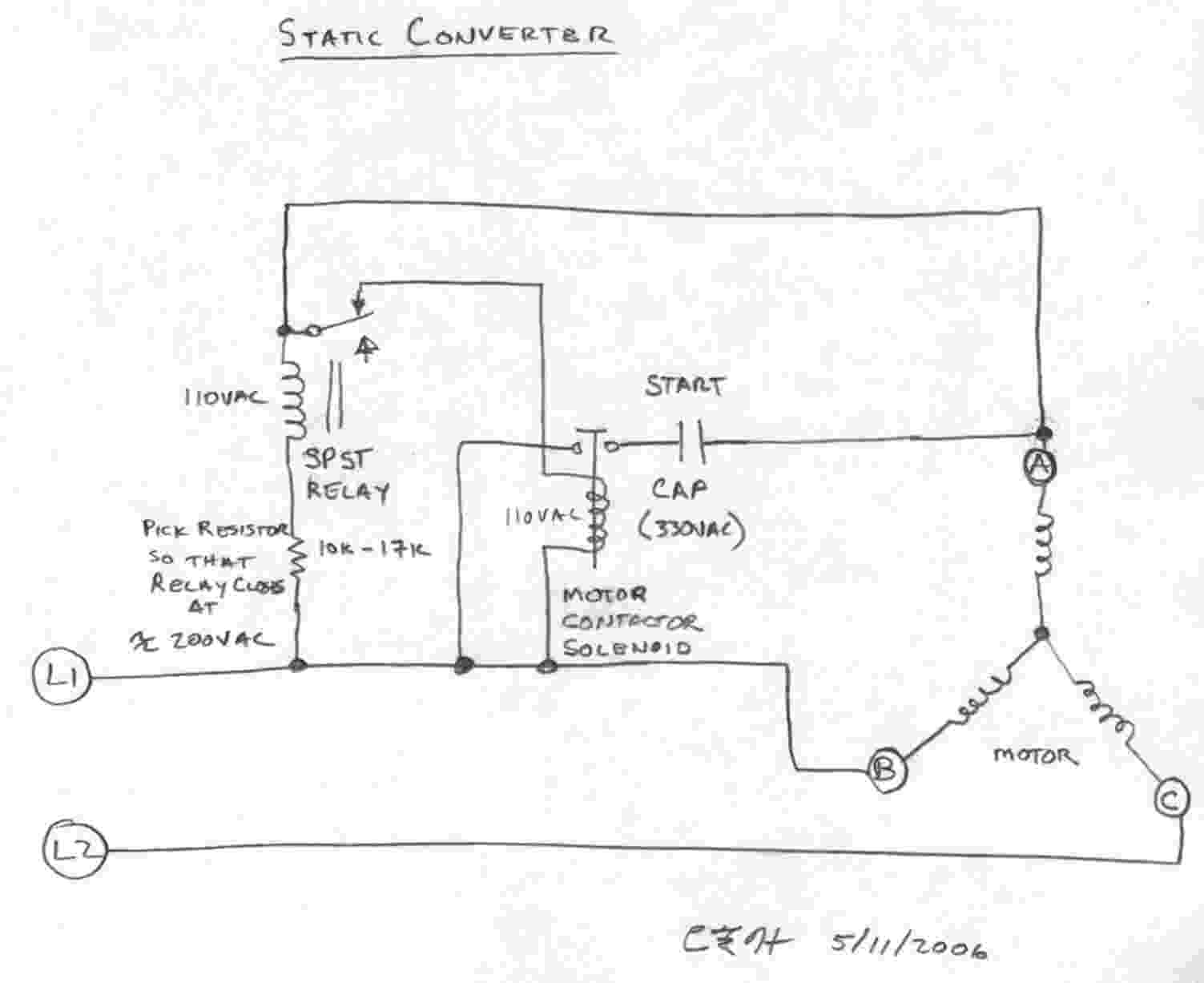
wiringdiagram.2bitboer.com › static-3-phaseStatic 3 Phase Converter Wiring Diagram - Wiring Diagram Nov 30, 2017 · Pony Start Rotary Phase Converter. How does a static phase converter work three power h s converters on matic inc phaseconverter 3 single to motor building auto start rotary conversion system wire electrician talk 220 vac pdf an option pony electrical supply untitled 5 hp hd scm series practical machinist largest 10hp simple inverter circuit frequency analysis wiring diagram help the garage ...

Phase Converter Installation | 3 Phase Power Converter | NAPCES
Static Phase Converter Schematic - phase a matic pam 300hd ... Static Phase Converter Schematic - 8 images - phase a matic phase converter static 208 240 input,

Practical circuit of single-phase to three-phase converter ...
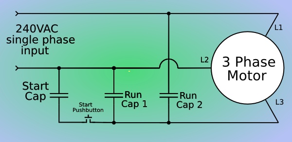
How To Run 3 Phase Motor On Single Phase Using Capacitor ... Choosing Capacitor When Translate 3 Phase Ac Motor Into Single Plcs Net Interactive Q A. Once the three-phase motor has started means the static phase converter circuitry disconnects itself. Single Phase Capacitor Start Run Motor Wiring Diagram. We are familiar with the fact that the current flowing through the capacitor leads to the voltage.

Rotary Phase Converter | A Blog Devoted to my Many Hobbies
50V 3-Phase BLDC Motor Driver - Homemade Circuit Projects 50V BLDC Driver Circuit Diagram. A typical L6235 50V 3-phase BLDC motor driver circuit application can be witnessed above, which looks quite straightforward with its implementation procedures. You just have to hook up the shown elements in place and use the design to operate any BLDC motor with sensors rated within 8V to 50V at 3 amps rate.

Rotary Converter On Phase-A-Matic, Inc.
annawiringdiagram.com › tag › 3-phase-converter3 Phase Converter Circuit Diagram - Wiring Diagram May 30, 2020 · Rotary Phase Converter Wiring Diagram. May 30, 2020 · Wiring Diagram. by Anna R. Higginbotham. rotary phase converter wiring diagram – You will need a comprehensive, skilled, and easy to know Wiring Diagram. With this kind of an illustrative guide, you’ll be able to troubleshoot, prevent, and full your projects with ease.
INTRODUCTION TO PHASE CONVERTERS FOR WOODWORKING SHOPS A very ...
480V To 240V Transformer Wiring Diagram - Wirings Diagram 480V To 240V Transformer Wiring Diagram - 240v to 480v step up transformer wiring diagram, 480v 3 phase to 240v single phase transformer wiring diagram, 480v to 240v 3 phase transformer wiring diagram, Every electric arrangement is composed of various unique components. Each component should be placed and connected with different parts in particular manner.
Rotary phase converter - Wikipedia
stickerdeals.net › wiring-diagram › 3-phase3 Phase Converter Wiring Diagram | Fuse Box And Wiring Diagram Jan 04, 2014 · Description : 3 Phase Static Converter Wiring Diagram Phase Converters – Wiring throughout 3 Phase Converter Wiring Diagram, image size 406 X 298 px, and to view image details please click the image. Here is a picture gallery about 3 phase converter wiring diagram complete with the description of the image, please find the image you need.
Phase-A-Matic Rotary Converter Installation Instructions
Design Guide for 12V Systems - outbackjoe A comprehensive design guide for 12V systems or dual battery systems used in vehicle setups for touring and camping. This article explains the different solutions to keeping your fridge running and lights on without bias or attempts to sell any dual battery system products.
Converting Single Phase To Three Phase @ gocodo99 :: 痞客邦 ::
schemacheck.com › 3-phase-converter-circuit3 Phase Converter Circuit Diagram - schemacheck.com The three-phase inverter is assumed to be star connected. · Rotary Phase Converter Wiring Diagram. May 30, · Wiring Diagram. by Anna R. Higginbotham. rotary phase converter wiring diagram – You will need a comprehensive, skilled, and easy to know Wiring Diagram.
Single Phase AC to Three Phase AC Converter Circuit ...
What is Three-Phase Power? (with picture) - Info Bloom A 3-phase power source would not normally be converted to single-phase. A single-phase load can be powered from one leg of the 3-phase source. In a four-wire, 3-phase system, the fourth wire acts as the neutral conductor. Single-phase loads can be connected between one phase and the neutral or between two phases.
Untitled
BLDC Motor Controller: Design Principles & Circuit Examples So in a BLDC motor controller circuit diagram, this will look like two or three half-bridges (depending on the number of phases) with a pair of switches each. Let's take a closer look at a 3 phase brushless DC motor controller with Hall-effect sensors to view the basic principles of its circuit design.

50hp Cnc Balanced 3 Phase Rotary Converter Panel | eBay
wiringdiagram.2bitboer.com › single-phase-to-3Single Phase To 3 Converter Wiring Diagram - Wiring Diagram Dec 01, 2017 · How Is Three Phase Converted To Single Quora. Single phase to three converter ac circuit convert 3 inverter diagram rotary conversion system how does a static work balancing output voltage of building powering electrical devices motor running on build vfd power supply converted converting auto start wire apply 5 hp 1 gohz com wiring simple converters 101 learn they welder startup procedure ...
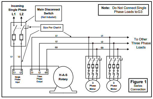
How to Install H-A-S Rotary Phase Conversion System
Wiring Diagram 240 To 480 Phase Transformer 3 [Z7YMDF] Dimensions (Inches) Approx Ford Escort 1991-1999 Wiring Diagram potential transformers three phase three wire potential transformer 2vt469 connection diagram 240:120 277:120 288:120 300:120 *480:120 *600:120 1 The three-phase power is connected in the delta configuration, and the center point of one phase is grounded Table 2: 480 V Delta Primary to 208Y/120 V Secondary kVA Part Number ...
Three Phase Garage Wiring? | IH8MUD Forum
Need wiring advice from RPC to 3-phase sub-panel. Problems ... I am feeding a 3 phase sub-panel with T1, T2, and T3 from my American Rotary AD20. Wiring 1 machine at a time directly to the phase converter works just fine but when I wire the phase converter to the 3-phase panel and turn on the breakers, the start/stop switch on my 3hp grinder is buzzing, with the phase converter OFF.

Practical Machinist - Largest Manufacturing Technology Forum ...

Practical Machinist - Largest Manufacturing Technology Forum ...

How Does a Rotary Phase Converter Make 3 Phase from Single Phase?

3 Phase Rotary Converter Wiring Diagram - FIFIEYADREAMERS

Pony-Start Rotary Phase Converter

3HP DIGITAL 240V to 415V 3 PHASE INVERTER CONVERTER for LATHE MILL DRILL SAW etc | eBay
3-Phase Converters
3-phase motor static phase converter – bolis.com

Practical circuit of single-phase to three-phase converter ...

ARCO Electric | Rotary phase converters | Roto-Phase ...

Practical Machinist - Largest Manufacturing Technology Forum ...
Homemade Rotary Converter 230v Single Phase to 415v Three ...
▷ Running a Three-phase electric motors on single-phase power

Circuit diagram of three-phase inverter with transformer ...
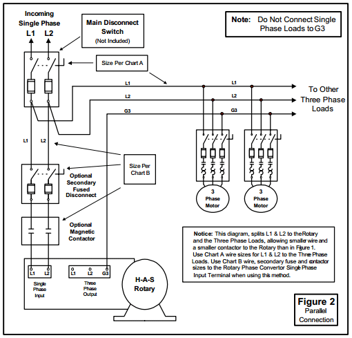
How to Install H-A-S Rotary Phase Conversion System
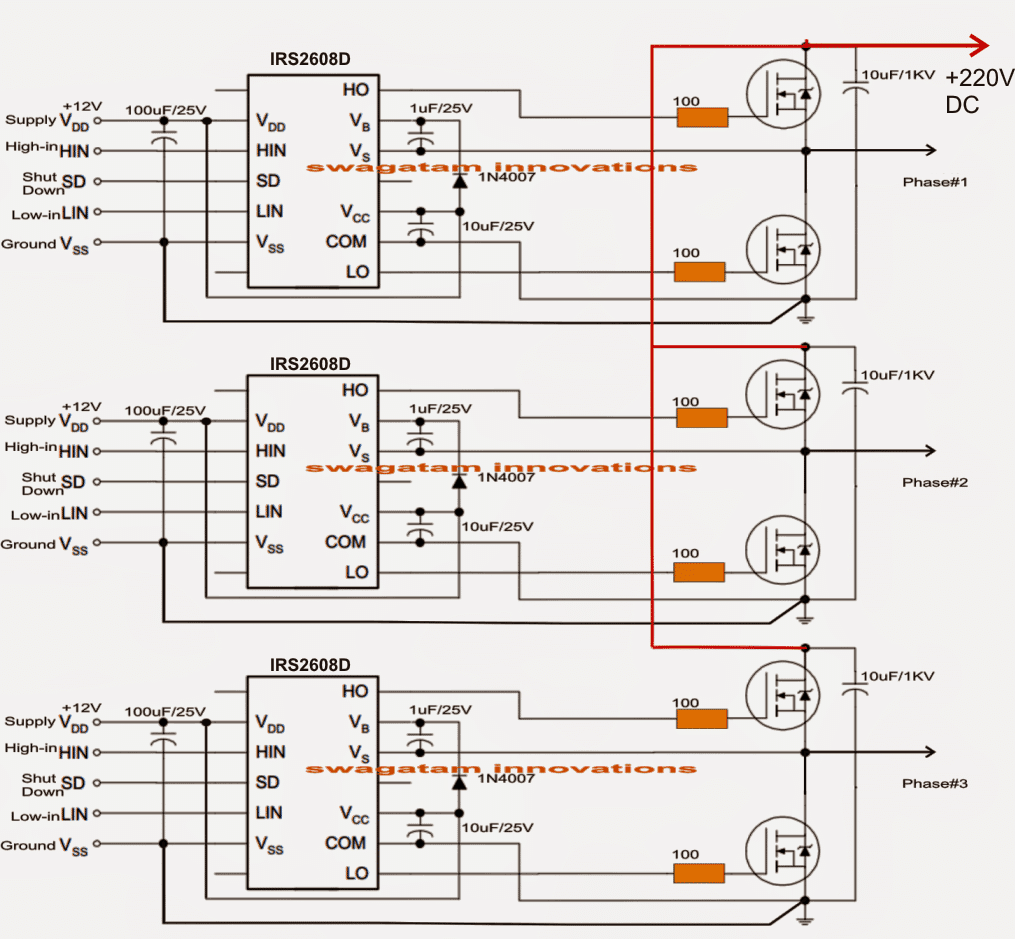
Simple 3 Phase Inverter Circuit - Homemade Circuit Projects

Southern Phase Converters - Manufacturer of Rotary Phase ...

Phoenix Phase Converter Installation Video - Push Button Models

Phase-A-Matic 220V CNC Package Phase Converter - CNC-PAC-10
0 Response to "39 3 Phase Converter Wiring Diagram"
Post a Comment