38 liquid vapor phase diagram
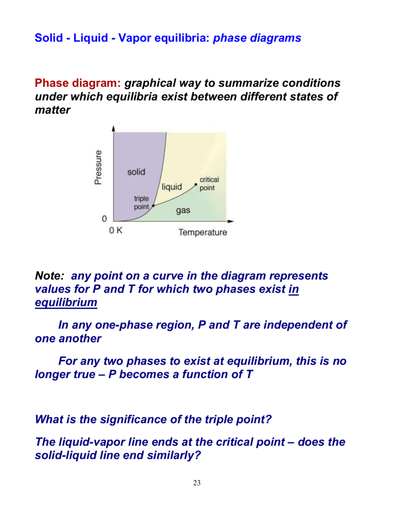
•Binary Vapor-Liquid Systems-Examples of binary system-Phase equilibrium diagram-q-line-Phase diagram for constant relative volatility •AzeotropicSystems. Phase Separation • Simplest separation processes V-Two phases in contact physical equilibrium phase separation Point B in this phase diagram represents the only combination of temperature and pressure at which a pure substance can exist simultaneously as a solid, a liquid, and a gas. It is therefore called the triple point of the substance, and it represents the only point in the phase diagram in which all three states are in equilibrium.
In thermodynamics and chemical engineering, the vapor–liquid equilibrium (VLE) describes the distribution of a chemical species between the vapor phase and a liquid phase.. The concentration of a vapor in contact with its liquid, especially at equilibrium, is often expressed in terms of vapor pressure, which will be a partial pressure (a part of the total gas pressure) if any other gas(es ...

Liquid vapor phase diagram
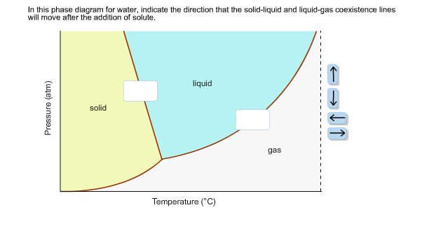
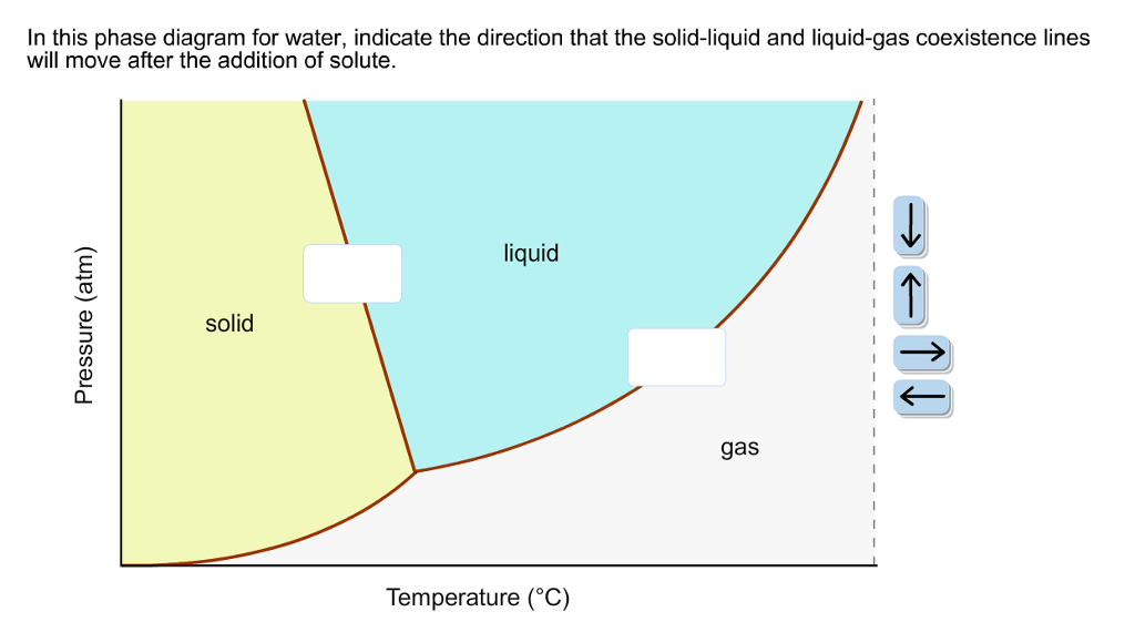
Calculation of vapor-liquid equilibrium (VLE) and drawing of phase diagrams. Name of substance. CAS-nr. Formula. Type of substance. acetone. 67-64-1. C 3 H 6 O. ketone. A phase diagram in physical chemistry, engineering, mineralogy, and materials science is a type of chart used to show conditions (pressure, temperature, volume, etc.) at which thermodynamically distinct phases (such as solid, liquid or … An unusual feature of the water phase diagram is that the solid–liquid phase line (illustrated by the dotted green line) has a negative slope. For most substances, the slope is positive as exemplified by the dark green line. This unusual feature of water is related to ice having a lower density than liquid water.
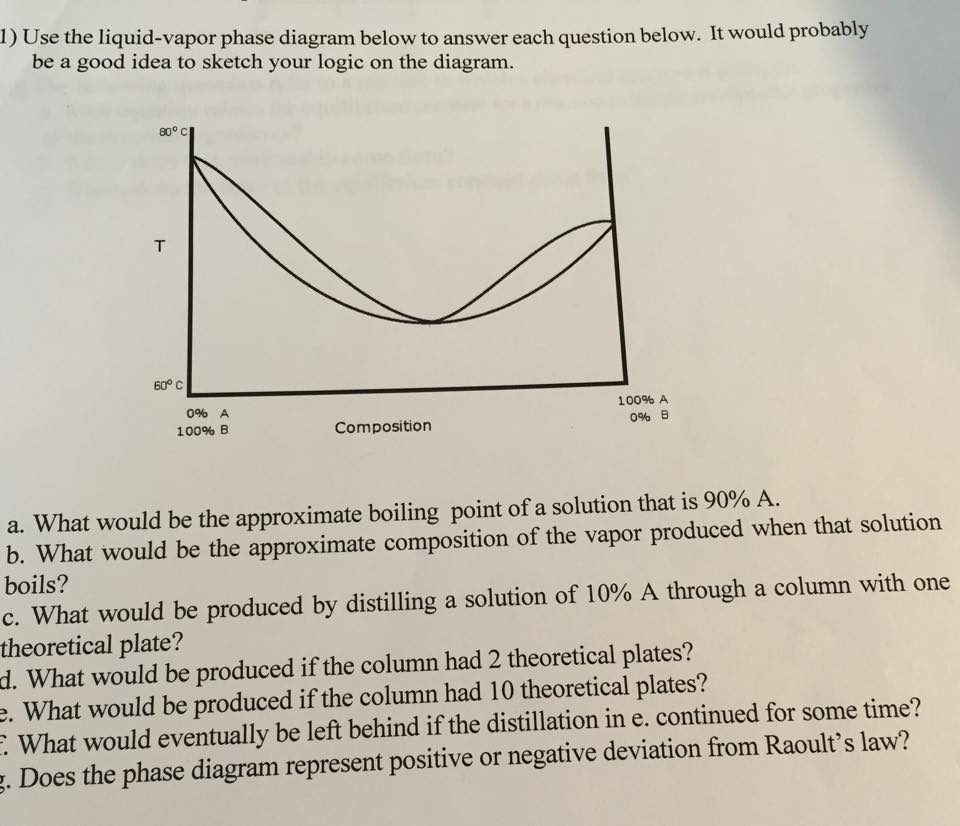
Liquid vapor phase diagram. BINARY LIQUID-VAPOR PHASE DIAGRAM 2 Abstract The goal of the lab is to construct a binary liquid-vapor phase diagram using refractometry and the heterogeneous equilibrium between two phases in a system of two components. Also, the idea of Raoult's Law was applied to the experiment to determine the negative relationships in two diagrams. A liquid-vapor phase diagram plots temperature of mixture versus the mole fraction or composition. A phase diagram of 2 components that will have differing molecular interactions causing mixture’s boiling point to rise/drop will show an azeotrope, in which there will be 2 lobes that either concave down/up depending on if there’s positive ... Phase Diagram for Water. Water is a unique substance in many ways. One of these special properties is the fact that solid water (ice) is less dense than liquid water just above the freezing point. The phase diagram for water is shown in the Figure below . Figure 13.26. Liquid/Vapor Equilibria Ideal Solid/Liquid Equilibria Ideal Eutectic Non-Ideal Congruent melting solid solution Phase diagram is split into two phase diagrams with a special composition that acts as a pure component Same crystallographic structure in solid solution phase Different crystallographic structures in solid solution phases 12 L => a L ...
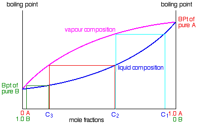
Chapter 8 Phase Diagrams. (b) The interpretation of diagrams. Point a represents the vapor pressure of a mixture with liquid composition xA and b represents the composition of the vapor that is in equilibrium with the liquid at that pressure. Note that when two phases are in equilibrium, P = 2, so F’ = 1. Expt. 5: Binary Phase Diagram CHEM 366 V-1 Binary Solid-Liquid Phase Diagram Introduction The substances that we encounter in the material world are hardly ever pure chemical compounds but rather mixtures of two or more such compounds. The individual substances in such a mixture may behave more or less independent of each other but merely ... Phase Determination (Case 1 Cont’d) • Case 1: Given P and T – Look up saturation table – Compare given P and T against saturation values in the table ¾In temperature table, Recall constant temperature line on P-v diagram If P > P sat(T), compressed liquid. If P = P sat(T), saturated liquid-vapor mixture. If P < P sat(T), superheated vapor. Because of the partial miscibility, vapor-liquid equilibrium (VLE), liquid-liquid equilibrium (LLE), and vapor-liquid-liquid equilibrium (VLLE) are present on the phase diagram. You can vary the mole fraction of component B and the heat added (location of the black dot).
Ternary phase diagrams are used to represent all possible mixtures of three solvents [1]; they are described in Chapter 3.Here, we shall indicate how they should be used to minimize the solvent consumption. Figure 2.1 (top) shows the methanol–chloroform–water ternary phase diagram with the tie-lines in the biphasic domain. Five particular compositions are shown in the … When liquid is cold, say water at 0°C at normal pressute, there will be absolutely no water vapour at its surface as all water has solidified. It will be called as low vapor pressure. When water is boiled at normal pressure, 100°C, all the water will begin to vaporize and all its surface will be occupied by vapour. Jan 20, 2014 · A liquid-vapor phase diagram of a binary system can be constructed by using a reflux apparatus. When a mixture of two soluble liquids is heated to a boiling point, the vapor phase is condensed and trapped in the pocket below the condenser. We will call the values for the liquid phase wt% PrOH, l, for the vapor phase wt% PrOH, v. Notice that for every value of T you have two values of wt% (liquid phase and vapor phase). Arrange the data from both parts A and B above into one set, sorted in order of increasing wt% PrOH.
Place all liquids in the appropriate waste solvent container. Remove and discard the septum. Examine the septum liner, and discard it if damaged. Results and Analysis Prepare a liquid-vapor phase diagram (temperature as a function of the liquid's composition). It is highly recommended that you prepare this diagram as you obtain the data.
The vapor-phase chemical potential of component j can be expressed in terms of vapor mole fraction y j, the total system pressure P, and fugacity coefficient s j. mV j¼ y Ps j Therefore, the general relationship between vapor and liquid phases is y j Ps ¼ x PSg j If the pressure of the system is not high, the fug acity coefficient is unity.
• The distillate is a two-phase mixture of b 3’ and b 3’’ • A system at e 1 forms two phases, which persist up to the boiling point at e 2. The vapor of this mixture has the same composition as liquids (azeotrope) • Condensing a vapor of composition e 3 gives a two-phase liquid of the same overall composition
phase region we have a vapor phase and a liquid phase in equilibrium with each other. Thus, a point in this region must correspond to two different compositions. The way we find these two different compositions is to draw a "tie line." There is no indication on the above diagram what the composition of the vapor is at each pressure. We know
Phase diagram of water Note: for H2O melting point decreases with increasing ... When molecules in the gas phase collide with the liquid surface, ... condensation become equal and the system is at equilibrium. The partial pressure of the vapor above the liquid established at equilibrium is called the equilibrium vapor pressure or just vapor
17.2 Observation 1: Liquid-Vapor Phase Diagram In the previous study, we examined experimental data on the vapor pressures of di erent liquids as a function of their temperature. We found that the vapor pressure of a liquid depends strongly on what the liquid substance is.
Summary: A vapor containing 90 mol% pentane (y = 0.9) could be compressed to 7.5 atm (at 400 K), at which point it would be a saturated vapor (red line), and it would begin to condense.The saturated liquid (blue line) in equilibrium with the vapor contains less of the more volatile component, n-pentane.The composition of this saturated liquid is 65 mol% n-pentane (y = 0.65).
The answer is, path F-G is represented by one point in Figure 3.2; that is, point C. Recall, for a single-component system, dew points and bubble points are identical. During a phase transition, both pressure and temperature must remain constant for pure components. Now, if we want to generate all the possible points that make up the vapor pressure curve in Figure 3.2, we would need to repeat ...
Distillation has a close importance to liquid-vapor phase diagrams, and boiling point diagrams. Distillation consists of boiling a liquid and condensing the vapor into a receiver which will lead to the partial or complete separation of a liquid into its components [1].
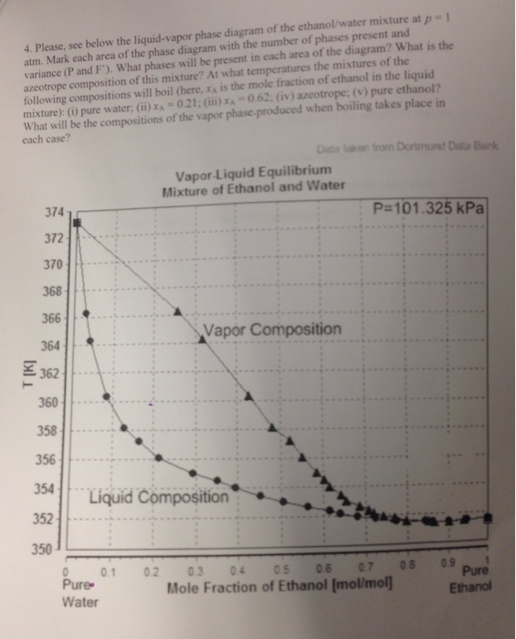
Liquid/Vapor phase diagram for ethanol/water solution. Post by rubelstrudel » Tue Sep 10, 2019 11:04 am I am using the liquid/vapor phase diagram for ethanol/water solution all the time. It gives me all the information I need about my still by just measuring the temp in the top of the column while running. I found this nice chart by googling:
Vapor Liquid Phase Diagrams. Vapor-liquid equilibrium data may be obtained by experiment, by thermodynamic calculation, or in published sources. It is typically presented either in tabular form or as an equilbrium diagram. Diagrams may take several forms: boiling point diagrams Txy, Pxy diagrams ternary diagrams solubility diagrams
Consider a binary mixture of ethanol and water. Vapor-liquid equilibrium (VLE) data can be computed using the modified Raoult's law: , where is the vapor pressure, is the total pressure, and are the liquid and vapor phase mole fractions of the light component (i.e., ethanol) when , and finally, is the activity coefficient. You can vary the pressure to any value between and (i.e., …
the vapor phase is a saturated vapor. Liquid water continues to evaporate with additional heat until it becomes all saturated vapor at point (g). Any further heating will cause an increase in both temperature and specific volume and the saturated vapor becomes superheated vapor denoted by point (s) in Figure 3.2-2. For a two-phase liquid-vapor ...
3.3 Phase Diagram for Water Vapor: Clausius–Clapeyron Equation. The Clausius–Clapeyron Equation. We can derive the equation for e s using two concepts you may have heard of and will learn about later: entropy and Gibbs free energy, which we will not go into here.Instead, we will quote the result, which is called the Clausius–Clapeyron Equation,
• Phase Diagram for Cu-Ni system Adapted from Fig. 9.3(a), Callister 7e. (Fig. 9.3(a) is adapted from Phase Diagrams of Binary Nickel Alloys , P. Nash (Ed.), ASM International, Materials Park, OH (1991). • 2 phases: L (liquid) α (FCC solid solution) • 3 phase fields: L L + α α 0 20 40 60 80 100 wt% Ni 1000 1100 1200 1300 1400 1500 1600 ...
Liquid-Liquid Ternary Phase Diagram (these may be found in either mole% or wt%) (2) (3a) (3b) 1) What does the dark region represent? 2) What phase(s) is present at 10% A, 10% C and 80% B? How much of each phase is present? 3) What is the composition of the liquid in equilibrium with a liquid
Use phase diagrams to identify stable phases at given temperatures and pressures, and to describe phase transitions resulting from changes in these properties. In the previous module, the variation of a liquid’s equilibrium vapor pressure with temperature was described. Considering the definition of boiling point, plots of vapor pressure ...
which is the key to these vapor/liquid equilibrium problems. For bubble points, we know the pressure and liquid phase mole fractions . What's left to do is adjust the temperature until the vapor phase mole fractions add to one. Here we show how to formulate and solve for the bubble point of 50/50 mol% of benzene and toluene at 1 atm.
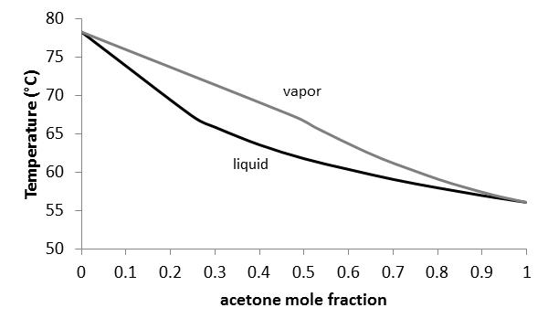
1.2 BINARY VLE PHASE DIAGRAMS Two types of vapor–liquid equilibrium diagrams are widely used to represent data for two-component (binary) systems. The first is a “temperature versus x and y” diagram (Txy). The x term represents the liquid composition, usually expressed in terms of mole fraction. The y term represents the vapor composition.
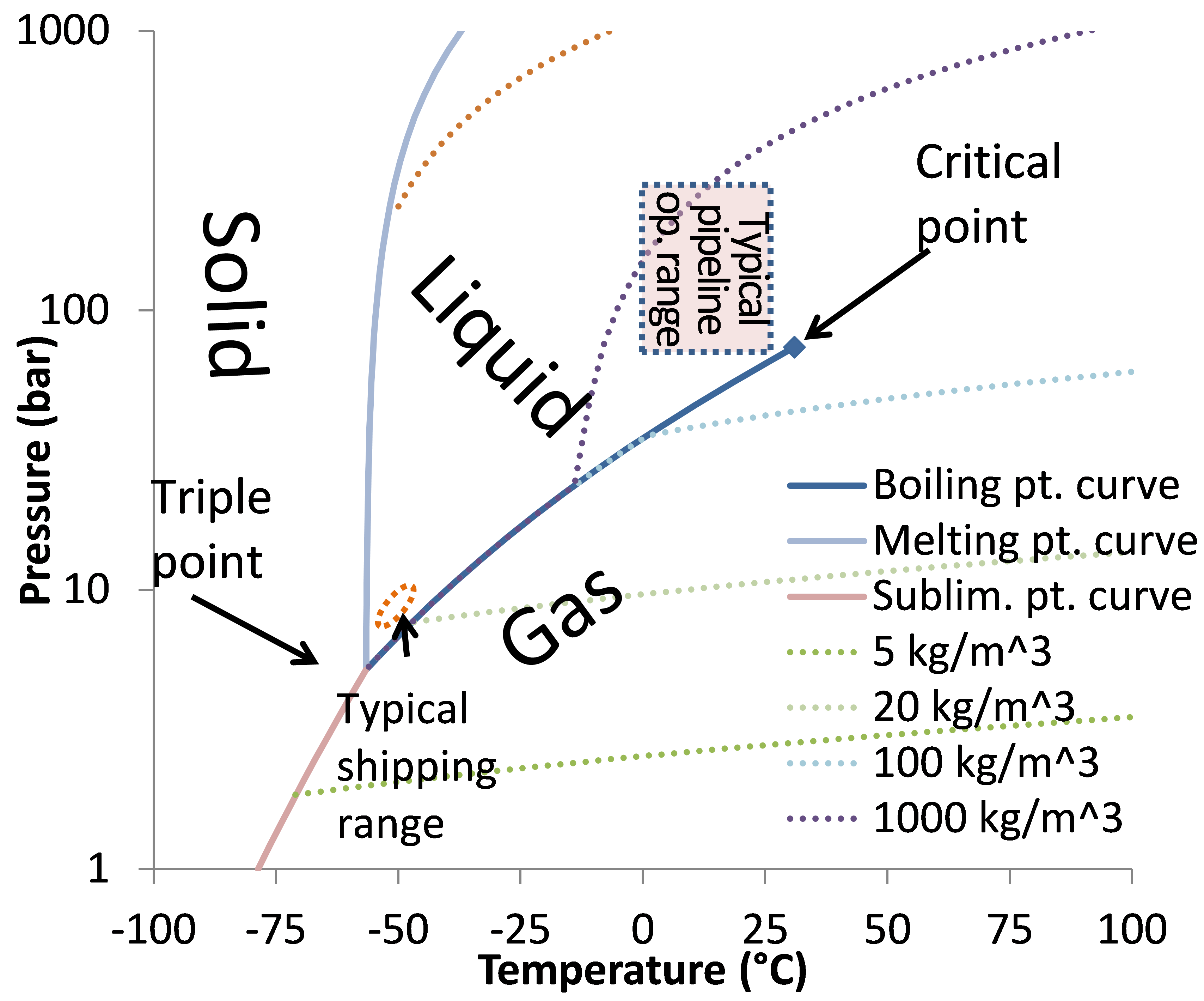
Phase diagrams are graphical representations of the liquid, vapor, and solid phases that co-exist at various ranges of temperature and pressure within a reservoir. Binary phase diagrams describe the co-existence of two phases at a range of pressures for a given temperature. Contents 1 Binary phase diagrams 2 References
An unusual feature of the water phase diagram is that the solid–liquid phase line (illustrated by the dotted green line) has a negative slope. For most substances, the slope is positive as exemplified by the dark green line. This unusual feature of water is related to ice having a lower density than liquid water.
A phase diagram in physical chemistry, engineering, mineralogy, and materials science is a type of chart used to show conditions (pressure, temperature, volume, etc.) at which thermodynamically distinct phases (such as solid, liquid or …
Calculation of vapor-liquid equilibrium (VLE) and drawing of phase diagrams. Name of substance. CAS-nr. Formula. Type of substance. acetone. 67-64-1. C 3 H 6 O. ketone.










0 Response to "38 liquid vapor phase diagram"
Post a Comment