37 ray diagram converging lens
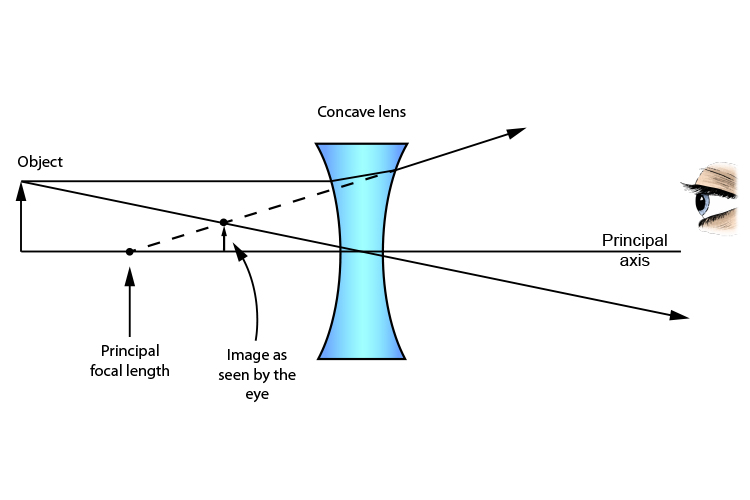
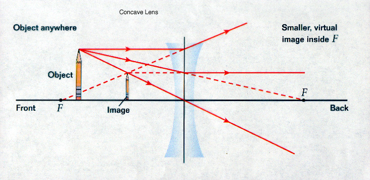
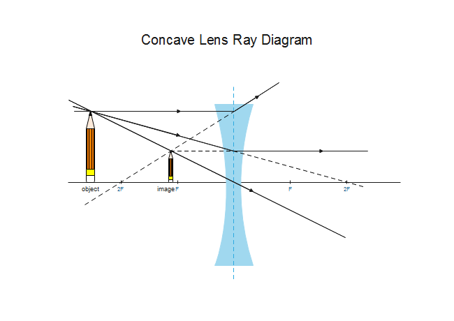
Ray diagram for an object viewed through a concave lens For an object viewed through a concave lens, light rays from the top of the object will be refracted and will diverge on the other side of... Plane mirrors produce images with a number of distinguishable characteristics. Images formed by plane mirrors are virtual, upright, left-right reversed, the same distance from the mirror as the object's distance, and the same size as the object.
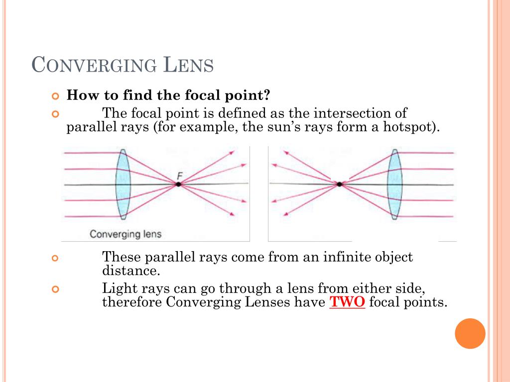
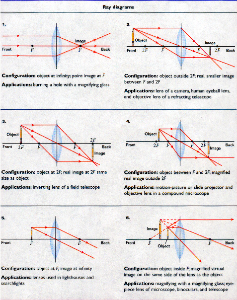
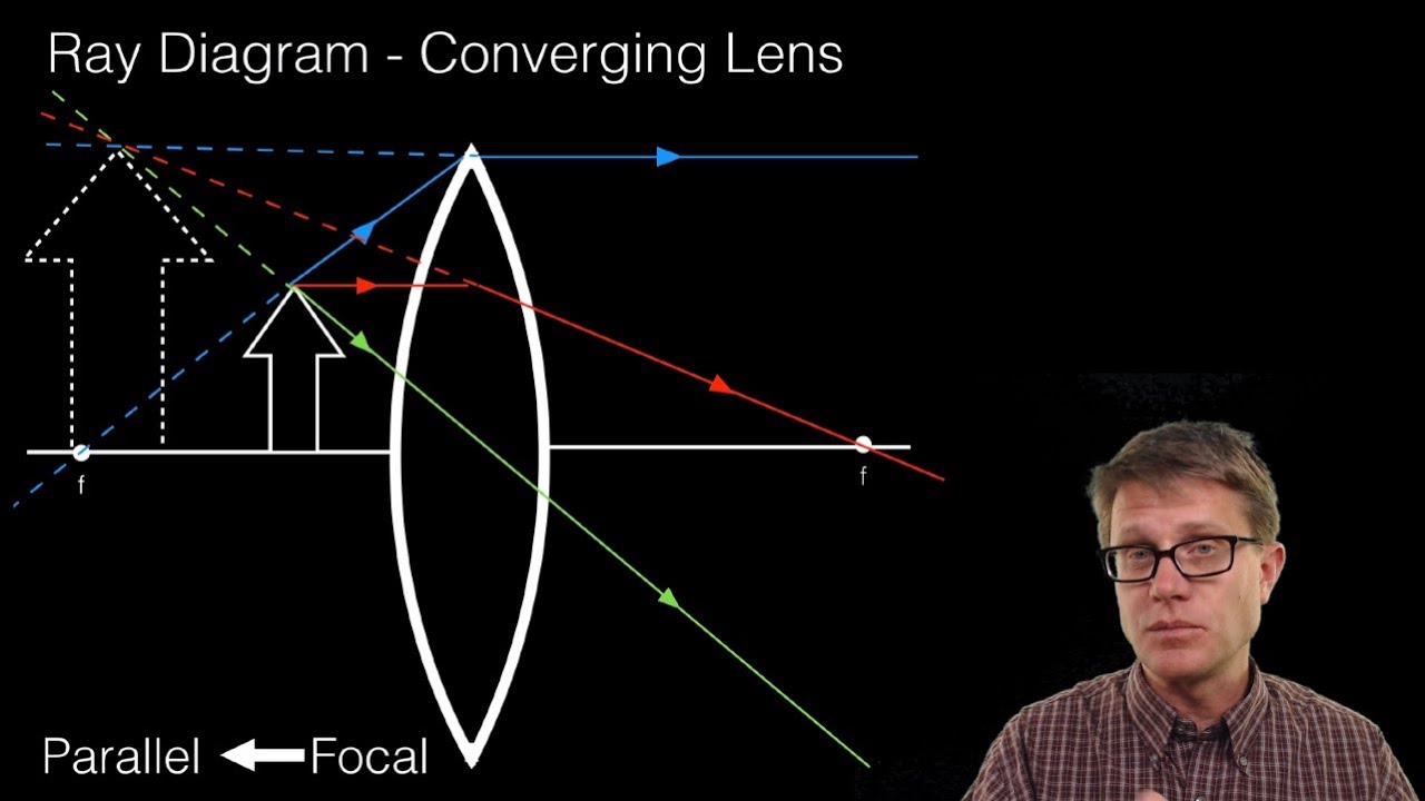
The red points on the ray diagram above are the focal points. Converging and diverging lenses A converging lens is one which the rays that enter it parallel to the axis converge toward the axis after exiting the lens. A diverging lens is one which these rays diverge away from the axis after exiting it.
Ray diagram converging lens
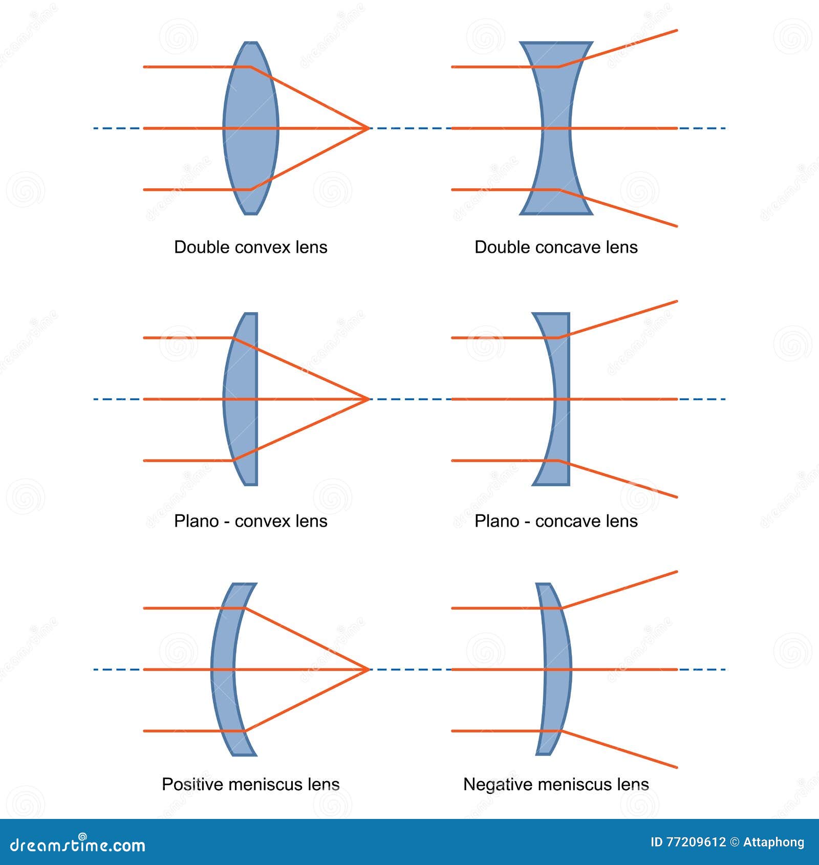
Shows how to draw ray diagrams to locate the image formed by a convex lens. You can see a listing of all my videos at my website, http://www.stepbystepscienc... Apr 26, 2020 · NCERT Question 10 - An object 5 cm in length is held 25 cm away from a converging lens of focal length 10 cm. Draw the ray diagram and find the position, size and the nature of the image formed View Answer NCERT Question 11 - A concave lens of focal length 15 cm forms an image 10 cm from the lens. How far is the object placed from the lens? • Light rays bent towards each other… CONVERGING LENS. • The less parallel the two sides, the more the light ray changes direction. • Rays from a single point, converge to a single point on the other side of the lens (and then start diverging again). We build lenses out of glass with non-parallel sides Put film, Retina here!
Ray diagram converging lens. 122 - Ray Diagrams - LensesIn this video Paul Andersen explains how ray diagrams for lenses can be used to determine the size and location of a refracted ima... Ray Diagrams By constructing a ray diagram, we can determine where the image is located, and what it will look like. A ray diagram is a diagram showing rays that can be drawn to determine the size and location of an image formed by a mirror or lens. This Demonstration lets you visualize the ray diagrams for converging and diverging lenses. By manipulating the object and lens locations, you can create real or virtual images. The rays parallel to the principal axis and the ray through the center of the lens are drawn. [more] Contributed by: Ernest Lee (November 2007) In a ray diagram, a convex lens is drawn as a vertical line with outward facing arrows to indicate the shape of the lens. The distance from the lens to the principal focus is called the focal...
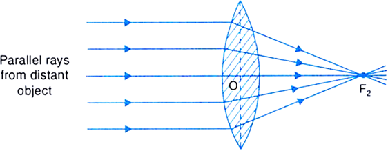
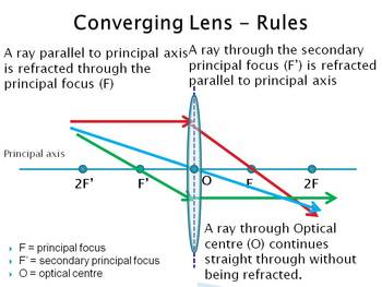
Converging Lens When using a thin lens, that is, the thickness at the center of the lens is not too great, a thin lens mathematical approximation can be used. This approximation assumes the bending of light occurs in one plane inside the lens. A ray of light coming from a very distant object, such that the ray is parallel to the optical axis ... Jul 07, 2020 · A converging lens is an optical lens that converges all rays of light passing through it. The primary purpose of a converging lens is to focus the incoming rays from an object and converge them to form an image. Ray diagram for converging lens. Ray 1 is parallel to the axis and refracts as if from F. Ray 2 heads towards F' before refracting parallel to the axis. Ray 3 passes straight through the center of the lens. image is always virtual, upright and reduced O F I F' Ray diagram for diverging lens Two Converging Lens Ray Diagram. Examples are given for converging and diverging lenses and for the cases where the The third ray is not really needed, since the first two locate the image. In this section of Lesson 5, we will investigate the method for drawing ray diagrams for objects placed at various locations in front of a double convex lens.
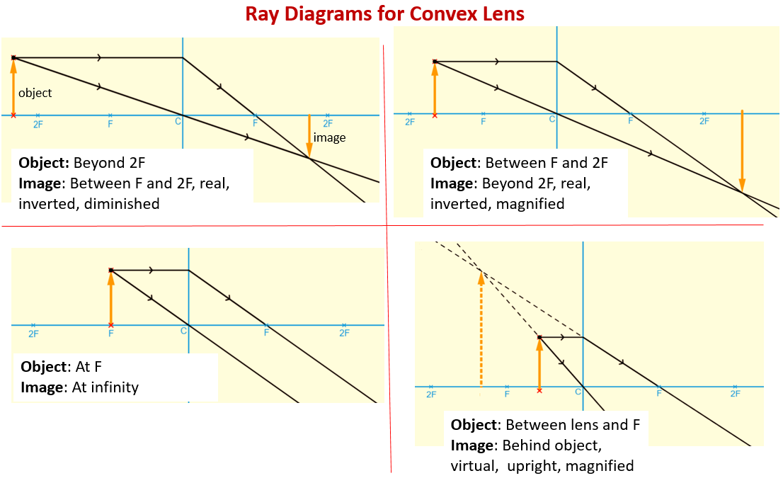
Ray diagrams for converging (convex) lens. Leave a Comment / Basic Physics Tutorials / By San Lohat. If an object is on one side of the convex lens, the convex lens can form the image of the object. If the position of the object on one side of the convex lens is known, how to draw the image formation of the object? Ray diagram for converging lens Ray 1 is parallel to the axis and refracts through F. Concave Mirror Ray Diagram Concave Mirror Ray Diagram lets us understand that when an object is placed at infinity a real image is formed at the focus. Ray 2 passes through F before refracting parallel to the axis. Ray Diagrams for Lenses The image formed by a single lens can be located and sized with three principal rays. Examples are given for converging and diverging lenses and for the cases where the object is inside and outside the principal focal length. The "three principal rays" which are used for visualizing the image location and size are: Diverging Lenses As such, the rules for how light behaves when going through a diverging lens is a little bit different. You will be expected to be able to draw a Ray Diagram of a converging and diverging lens on our upcoming test without the rules.
PPT - Pre-AP Physics Lenses & Ray Diagrams PowerPoint ...
Each case will use the three rays outlined in the resource lesson on converging lenses where you are provided with an animated gif to show you how the image is formed. First watch each animation, then draw your own diagram. Keep your three rays color-coded - that is, let ray #1 be the same color in each diagram, similarly with ray #2 and ray #3.

Convex Lense Ray Diagram — UNTPIKAPPS
What is a lens ray diagram? A convex lens is drawn as a vertical line with outward facing arrows to indicate the shape of the lens in a ray diagram, and the focal length is the distance between the lens and the principal focus. How do you draw a perfect ray diagram? Drawing Ray Diagrams: A Step-by-Step Guide
Ray Diagram For Converging Lens - Drivenheisenberg
To explain how to draw the diagrams, there are two key things to remember. 1 A converging lens refracts the light so that any ray of light parallel to the principal axis (the thick horizontal line) is turned to pass through the focal point. Rays of light parallel to the principal axis are all refracted through the focal point.
Ray Diagram Of Converging Lens - Drivenheisenberg
Ray diagrams are constructed by taking the path of two.A converging lens and a screen are so arranged that an image of the sun falls on the screen. Ray Diagrams for Lenses The distance from the lens to the screen is 1) the focal length. 2) the object distance. 3) the magnifying power. 4) one-half the radius of curvature of one of the lens faces. .
Converging Lenses Ray Tracing | Les Baux-de-Provence
An object of height 3 cm is placed at a distance of 25 cm in front of a converging lens of focal length 20 cm, to be referred to as the first lens. Behind the lens there is another converging lens of focal length 20 cm placed 10 cm from the first lens. There is a concave mirror of focal length 15 cm placed 50 cm from the second lens.
Convex Lens - Ray diagram, Image Formation, Table - Teachoo
The method of drawing ray diagrams for double convex lens is described below. The description is applied to the task of drawing a ray diagram for an object located beyond the 2F point of a double convex lens. 1. Pick a point on the top of the object and draw three incident rays traveling towards the lens.
Ray Diagram For Converging Lenses - Atkinsjewelry
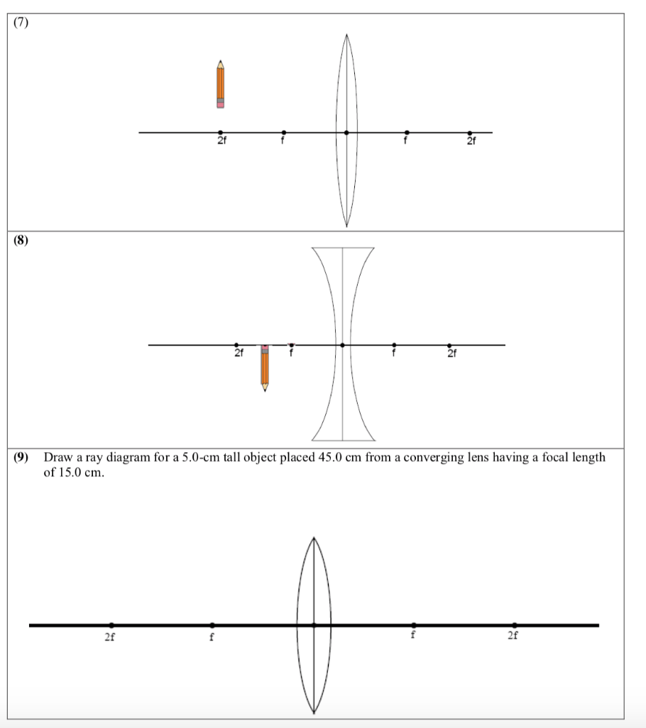
(10) Draw a ray diagram for a 3.0-cm tall object placed 10.0 cm from a converging lens having a focal length of 15.0 cm. (11) Draw a ray diagram for a diverging lens that has a focal length of -10.8 cm when an object is placed 32.4 cm from the lens's surface. (12) Draw a ray diagram for an object placed 6.0 cm from the surface of a converging lens with a focal length

optics - How do I experimentally find an image projected ...
the converging lens and the final image of the diverging lens. Ray diagrams for single converging and diverging lenses are shown in your textbook. CHAPTER 10. IMAGES WITH THIN LENSES 90 A simple ray diagram treats the object as a single point at the tip of an arrow drawn extending from

The Open Door Web Site : IB Physics : OPTICS : RAY ...
Here you have the ray diagrams used to find the image position for a converging lens. You can also illustrate the magnification of a lens and the difference between real and virtual images. Ray diagrams are constructed by taking the path of two distinct rays from a single point on the object. A light ray that enters the lens is an incident ray.

Lenses- Convex lens- Ray Diagrams - YouTube
The Physics Classroom » Curriculum Corner » Refraction and Lenses » Ray Diagrams for Converging Lenses. The document shown below can be downloaded and printed. Teachers are granted permission to use them freely with their students and to use it as part of their curriculum. Visit the Usage Policy page for additional information.
Method for drawing ray diagrams - Concave lens
Converging Lenses. There are three primary rays which are used to locate the images formed by converging lenses. Each ray starts from the top of the object. Ray #1. (aqua) runs parallel to the axis until it reaches the lens; then it refracts through the lens and leaves along a path that passes through the lens' principal focus. Ray #2.

choose the ray diagram that correctly locates the image ...
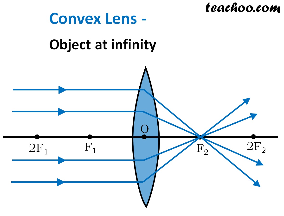
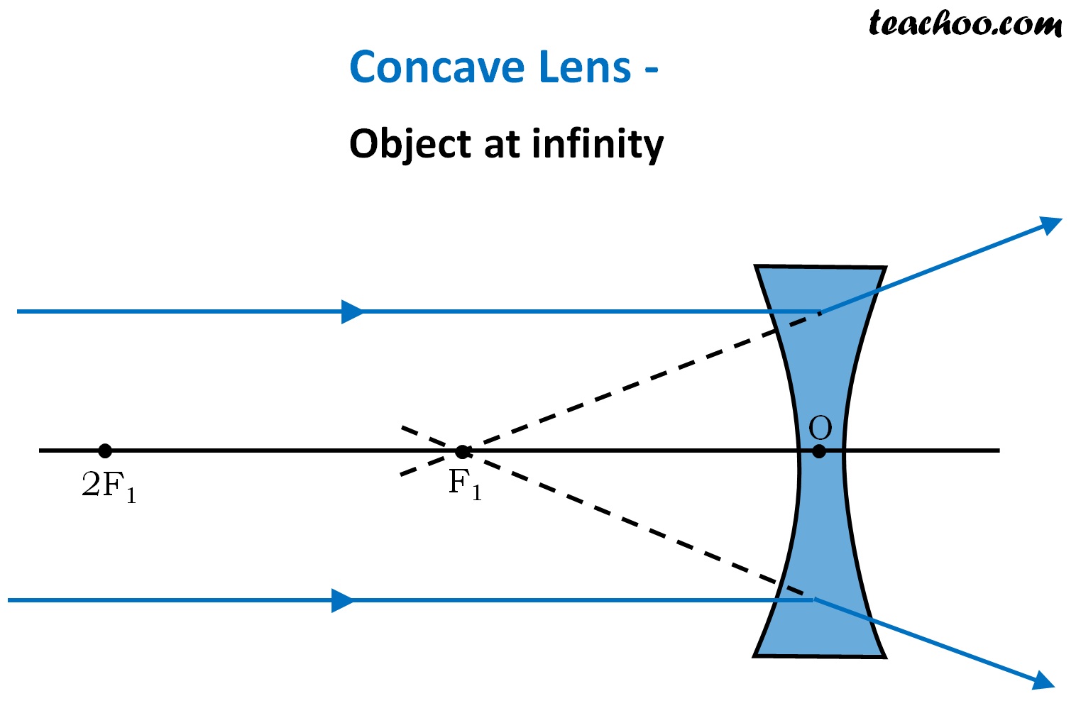
Convex Lens - Ray diagram. Last updated at Nov. 18, 2021 by . For a Convex Lens, object can be kept at different positions Hence, we take different cases Case 1 - Object is Placed at infinity In this Case, Object is kept far away from lens (almost at infinite distance)

My Physics Webschool: Ray Diagram
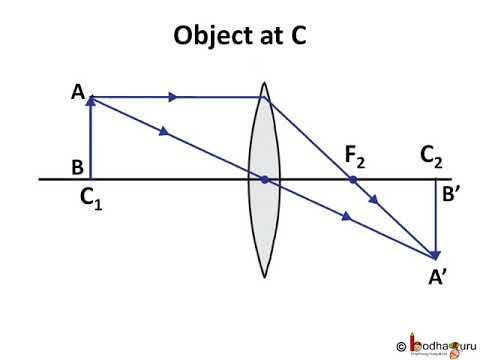
Trick to drawing ray diagrams for converging lens: There is one ray of light passing through the center of the lens. Always. 2 rays are enough to determine the position of image/object. The other ray of light ALWAYS passes through the focal point of the lens. Either the first focal point of the second focal point.

Image from page 234 of "The class-book of anatomy : designed for schools, explanatory of the first principles of human mechanism, as the basis of physical education" (1834)
Dec 10, 2019 · A diverging lens ray diagram follows three basic rules: Any ray of light that is parallel to the principal axis of the lens will pass through its focal point after refraction. Any incident ray of light that passes through the focus of the lens before getting refracted will emerge parallel to the principal axis on refraction.
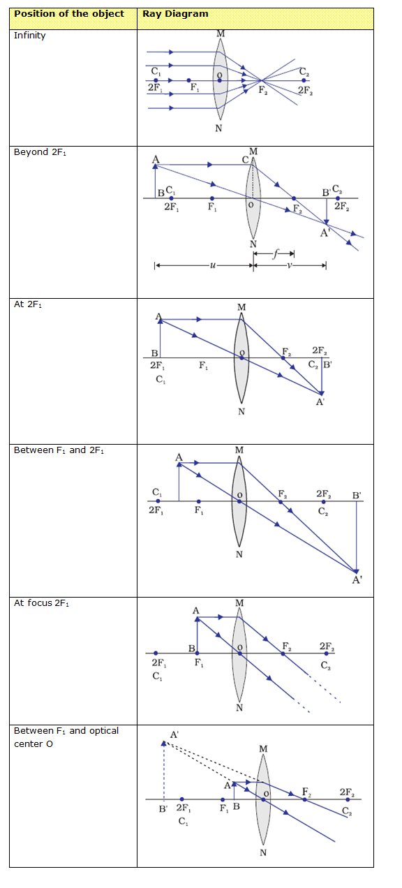
Image Formation in Lenses Using Ray Diagrams
autocollimator construction diagram. Generally, calibration is supplied with the instrument. Thus, the angle of inclination of the reflecting surface per division of the micrometer scale can be directly read. Autocollimators are quite accurate and can read up to 0.1 seconds, and may be used for a distance up to 30 meters.

Image from page 661 of "Kirkes' handbook of physiology" (1907)
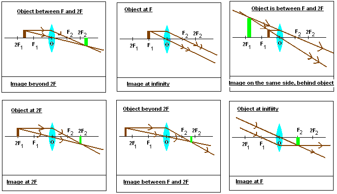
Ray diagrams for converging lens cases. Here is a video from Khan Academy that shows the ray geometry that explains the image formation for four different object distances relative to the lens and its focal points. A few key concepts are: YouTube. Light is reflecting from the o bject in all directions, but the only rays shown are the ones that ...
Ray Diagrams for Convex Lens - Online Science Home Work
• Light rays bent towards each other… CONVERGING LENS. • The less parallel the two sides, the more the light ray changes direction. • Rays from a single point, converge to a single point on the other side of the lens (and then start diverging again). We build lenses out of glass with non-parallel sides Put film, Retina here!
ray diagram for image formation by spherical lenses ...
Apr 26, 2020 · NCERT Question 10 - An object 5 cm in length is held 25 cm away from a converging lens of focal length 10 cm. Draw the ray diagram and find the position, size and the nature of the image formed View Answer NCERT Question 11 - A concave lens of focal length 15 cm forms an image 10 cm from the lens. How far is the object placed from the lens?
Solved: Converging & Diverging Lenses Ray Diagrams DIRECTI ...
Shows how to draw ray diagrams to locate the image formed by a convex lens. You can see a listing of all my videos at my website, http://www.stepbystepscienc...

31.Draw the ray diagram to show the formation of image by ...
35 Ray Diagram For Converging Lens - Wiring Diagram List

Lenses Concave and Convex: Drawing Ray Diagrams | TpT
Ray Diagrams for Lenses

The Open Door Web Site : IB Physics : OPTICS : RAY ...

Image from page 257 of "A manual of photographic chemistry, theoretical and practical" (1886)

Image from page 879 of "The physiology of the domestic animals; a text-book for veterinary and medical students and practitioners" (1890)
Ray Diagram Of Converging Lens - Hanenhuusholli
Ray Diagrams - Lenses - YouTube

Whanake, (v) in Te Reo Maori means to move onwards, move upwards. This was taken at Piha, Auckland, New Zealand. Piha Beach is famous for it’s stunning beaches but beauty can be found on a clifftop on the way to the beach from the carpark. This photo was taken during a photo expedition when I was out of a job, so the fact that it was taken on a whim on the way to the beach resonates that “it’s not about the destination, it’s about the journey.†It matters not what stage of life we’re in as long as we keep moving and looking for inspiration.
Ray Tracing Lenses
Ray Diagram Of Converging Lens - Atkinsjewelry

AP finishes worksheets on lenses, mirrors - AP Physics

Draw a labelled ray diagram for the formation of image by ...

Ray Diagrams For Diverging Lenses
Plano Convex Lens Ray Diagram - Drivenheisenberg
Concave Lens - Ray diagram, Images Formed - with Steps ...
Optics Unit - Ray Diagrams for Converging & Diverging ...
0 Response to "37 ray diagram converging lens"
Post a Comment