35 enphase micro inverter wiring diagram
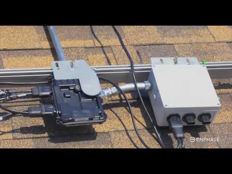
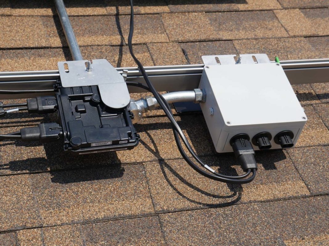
Installing Enphase micro inverters - Rooftop Work (micro inverters and cabling) The rooftop work for an Enphase system follows an easy, step-by-step process. Use the overview below as your guide or dig into the details in each of the sections that follow. Collection of enphase micro inverter wiring diagram. A wiring diagram is a streamlined standard photographic representation of an electric circuit. It reveals the parts of the circuit as simplified forms, as well as the power and signal links in between the gadgets.
Mar 03, 2021 · Before purchasing a charge controller, make sure it fits the solar panel system. The main parameter you're looking for is maximum amps. Amps of a controller must be bigger than the combined power of all solar panels divided by the voltage of the battery.

Enphase micro inverter wiring diagram
May 15, 2018 — Enphase Microinverter Installation. ... B. Refer to the wiring diagrams on page 40 for more information. Wire colors are listed in the.40 pages ENPHASE MICRO-INVERTER INSTALLATION 1. System Wiring Diagram 2. Once you have completed installing the roof mount system, attach the Micro-Inverters to the railing system using the nuts and bolts provided. You will need your Hex key and Spanner. Ensure the bolts are tightened securely. The Micro-Inverter must be under the module, out of Position the Enphase AC cabling. Install an AC branch circuit junction box / isolator. Attach the microinverters to the PV racking. Create a paper installation map. Ground the microinverters (if required) Dress the Enphase cabling. Connect the microinverters to the Enphase cabling. Terminate the unused end of the Enphase cabling and seal any ...
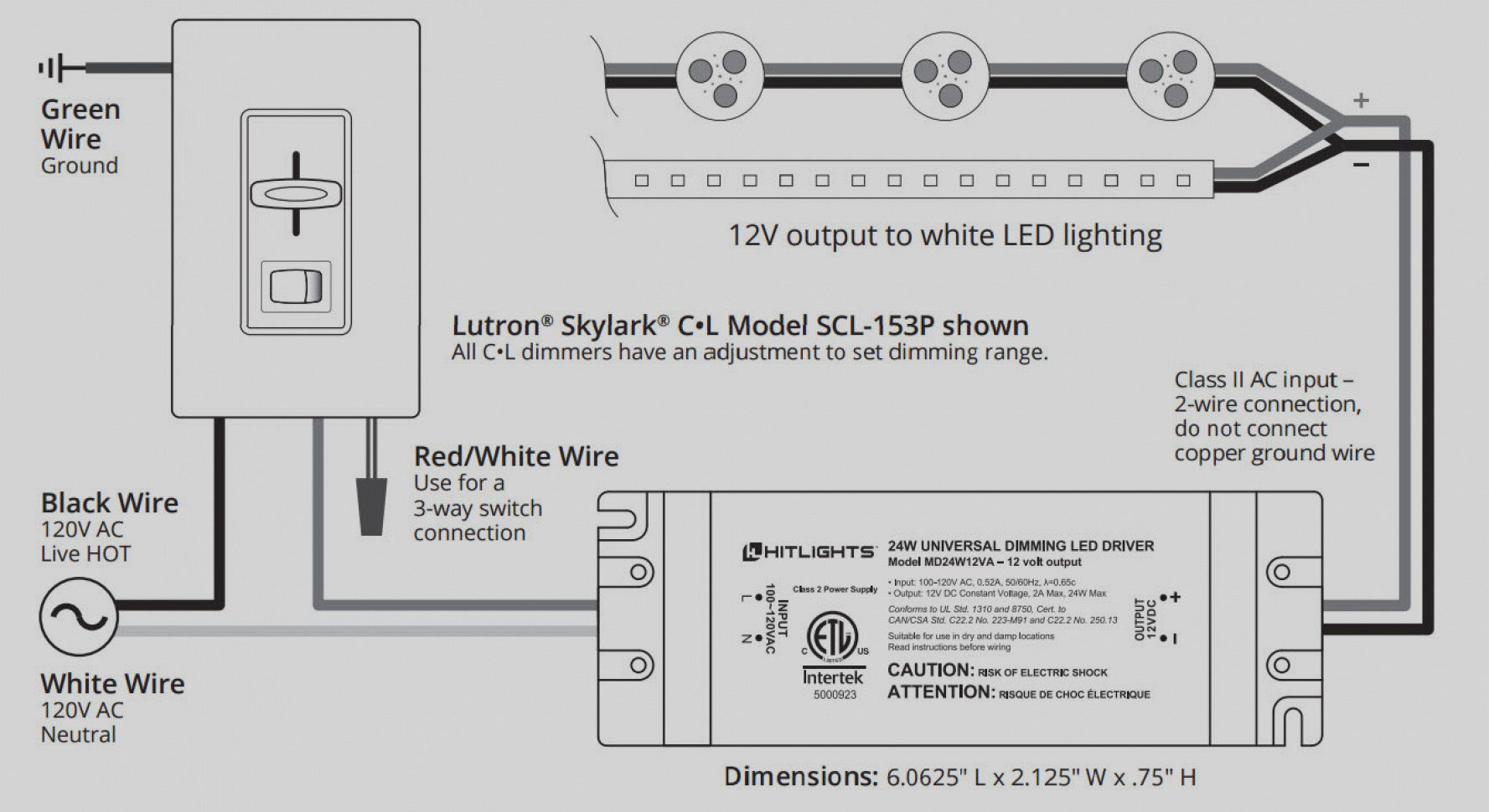
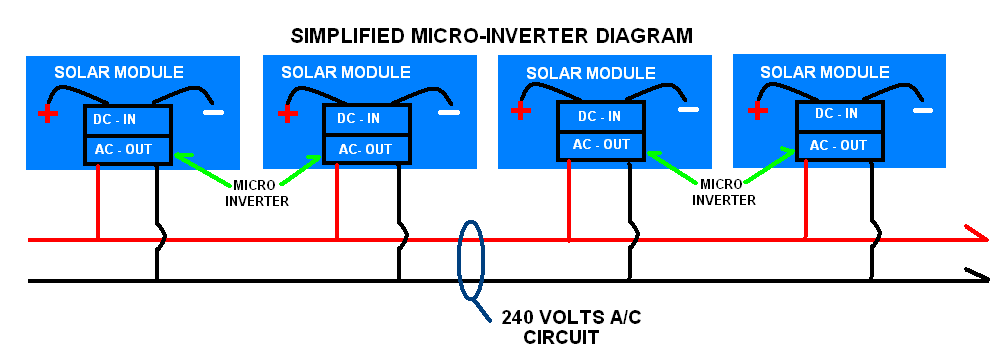
Enphase micro inverter wiring diagram. These are just a few of the ways in which the Enphase Micro-inverter System provides tremendous time, material and cost savings, while maximizing energy production and providing better return on investment from your system. Enphase Micro-Inverter Models The Enphase M190 Micro-inverters operate with most 60 and 72-cell PV module configurations. micro-inverters per envoy communications gateway ethernet cable ... prior to disconnecting ac connectors enphase ac interconnect cable black - l1 red - l2 orange - unused blue - neutral d c b a a 8 7 6 5 4 3 1 8 7 6 5 4 3 2 1 [e] enphase ... field wiring diagram 240 vac single phase m190-72-240-s1x, m210-84-240-s1x 144-00001 06-j. laughy 3/31 ... Enphase Micro Inverter Wiring Diagram Sample July 30, 2018 March 31, 2018 by faceitsalon Assortment of enphase micro inverter wiring diagram you can download for free. kia optima wire diagram , micro switch wiring commercial hood , electrical x and y , diagram as well enphase battery storage also dual battery wiring , 1999 dodge ram 1500 wiring ... Freedom 10 Inverter Circuit Diagram. 5v 10a 50w Offline Switching Power Supply. Simple Inverter Circuit Using Cd4047 And Uln2003. Enphase Micro Inverter Wiring Diagram Sample. Voltage Stability Enhancement Using Vswt With Direct Drive. Index Of Postpic 2009 01. 14 Pin Relay Base Wiring Diagram.
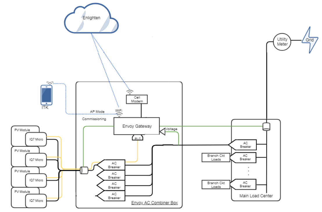
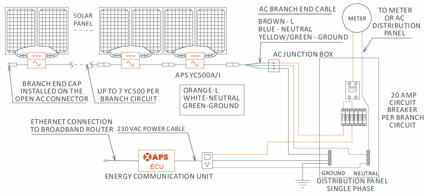
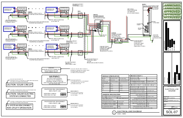
One-Line Standard Electrical Diagram for Micro-Inverter PV Systems Site Name: Site Address: System AC Size: SIZE FSCM NO DWG NO REV E1.1a SCALE NTS Date: SHEET Drawn By: Checked By: DESCRIPTION OR CONDUCTOR TYPE USE-2 or PV WIRE GEC EGC X ALL THAT APPLY EXTERIOR CABLE LISTED W/ INV. THWN-2 or XHHW-2 or RHW-2 GEC EGC X ALL THAT APPLY NO DC GEC ... NOTE: Ground PV modules according to local requirements. ENPHASE IQ 7 and IQ 7+ MICROINVERTER. FIELD WIRING DIAGRAM. © 2017 Enphase Energy Inc. All rights ...1 page Enphase M250 micro inverter. (10) 265W SolarWorld Modules each connecting to its own Enphase M250 micro inverter. 45A Service conductors extending to utility Existing Loads Existing Service panelboard meter J-box mounted at roof eave (for transition of NM cable to THWN-2 wire in conduit. 20A 20A 20A Note: this wiring diagram is simply an example. Jul 08, 2020 · Grid-Tie Wiring Path (Enphase Micro-Inverters) PV panel to micro-inverter ; Micro-inverter to trunk cable ; Trunk cables to junction box ; Junction box to main panel ; Enphase has a detailed solar panel installation video you can watch for a hands-on demonstration of the wiring process.
G ) Size the AC wire gauge to account for voltage rise. Select the correct wire size based on the distance from the beginning of the Enphase Q Cable to the breaker in the load center. Design for a voltage rise total of less than 2% for the sections from the Enphase Q Cable to the breaker in the load center. Collection of enphase micro inverter wiring diagram. A wiring diagram is a streamlined standard photographic representation of an electrical circuit. It reveals the components of the circuit as simplified shapes, as well as the power as well as signal connections between the tools. View and Download Enphase M installation and operation manual ... Mar 09, 2021 · RV inverter installation is simple: you attach it to the terminals of your house battery with large battery cables. For safety reasons, it is recommended to add a fuse or circuit breaker between an inverter and a battery. Some inverters already have a built-in fuse, so consult the manual for your inverter for more details. The Enphase Encharge 10™ battery is reliable, smart, simple, and safe. It provides the lowest lifetime energy costs with backup capability for both new and retrofit solar customers. As an installer, you can quickly design the right system size to meet the needs of the homeowner.
Enphase wiring diagram
Enphase Micro Inverter Wiring Diagram. Collection of enphase micro inverter wiring diagram. A wiring diagram is a streamlined standard photographic representation of an electric circuit. It reveals the parts of the circuit as simplified forms, as well as the power and signal links in between the gadgets. A wiring diagram generally gives details concerning the…
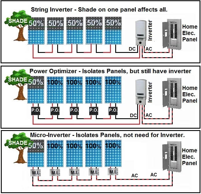
Inverters: Optimizers vs. Microinverters - PlugPV
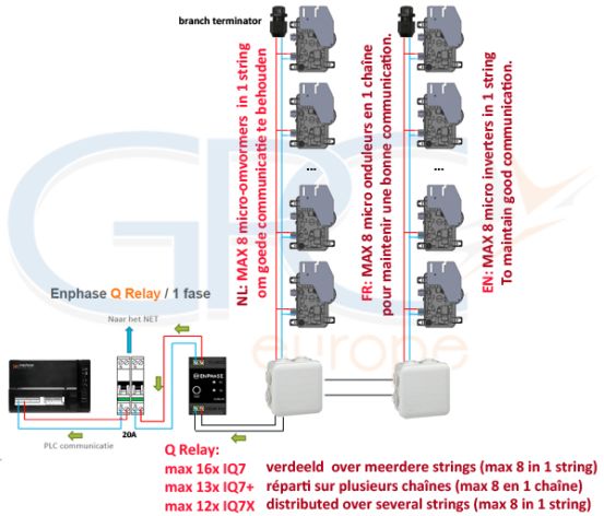
When installing the Enphase Q Cable, secure any loose cable to minimize tripping hazard. NOTES: When looping the Enphase Q Cable, do not form loops smaller than 4.75" (12 cm) in diameter. Provide support for the Enphase Q-Cable every 1.8m (6 feet). If you need to remove a sealing cap, you must use the Enphase disconnect tool.
60 Enphase Iq7 Wiring Diagram - Wiring Diagram Harness
Enphase Micro Inverter Wiring Diagram Sample July 30, 2018 March 31, 2018 by faceitsalon Assortment of enphase micro inverter wiring diagram you can download for free.

Enphase Micro Inverter Wiring Diagram | Free Wiring Diagram
When looping the Enphase Q Cable do not form loops smaller than 475 12 cm in diameter. 11880 Watts 240 VAC 495 amps of AC current. Enphase Micro Inverter Wiring Diagram Download. Enphase customer service to obtain an RMA return merchandise authorization number and start the.
Enphase Wiring Diagram
NOTE: Ground PV modules according to local requirements. ENPHASE IQ 7, IQ 7+, IQ 7A, and IQ 7X MICROINVERTER. FIELD WIRING DIAGRAM. © 2019 ...1 page
Enphase announces new Indian distributers and Chennai ...
User documentation is updated frequently; Check the Enphase website ... The Enphase Microinverter System . ... Sample Wiring Diagram: M215, 240 VAC .

Solar Micro Inverter Wiring Diagram Gallery
In homes with Enphase, SolarEdge or SMA PV arrays, a disconnect must also be placed between the inverter and the arrays. All solar array systems must be grounded. Grounding helps to mitigate the effects of lighting strikes and power surges.
Enphase wiring diagram
A wiring diagram is a streamlined standard photographic representation of an electric circuit. Attach the microinverters to the PV racking. Use the IQ Combiner 3 for single-phase applications and to support the AC connections needed for an Enphase residential solar installation. Enphase M250 micro inverter. Use Class 1 wiring methods for field ...

36 Enphase Micro Inverter Wiring Diagram - Wiring Diagram ...
The inverter sends the alternating current to the house or to the power grid, as needed. Inverters are placed near the structure's main electrical panel. Wiring and Electrical Panels. PV array components are connected with wiring, which must be able to accommodate the strength (the amperage) of the electrical current.
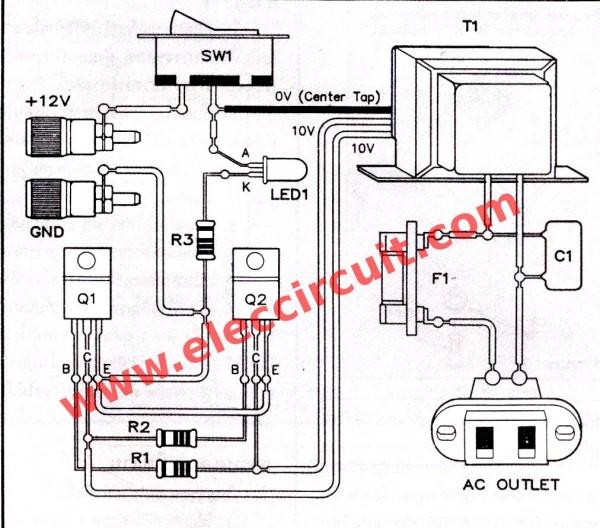
Simple inverter schematic diagram use MJ2955 - ElecCircuit
AC or DC wires are. For more information about Enphase Microinverters, visit the Microinverter Family The IQ System uses the 2-wire Q-Cable and a new line-to-line power line.Collection of enphase micro inverter wiring diagram. A wiring diagram is a streamlined standard photographic representation of an electrical circuit.
Magnum, MICROGT 500 Microinverter | eBay
G ) Size the AC wire gauge to account for voltage rise. Select the correct wire size based on the distance from the beginning of the Enphase Q Cable to the breaker in the load center. Design for a voltage rise total of less than 2% for the sections from the Enphase Q Cable to the breaker in the load center.
Enphase Micro Inverter Wiring Diagram
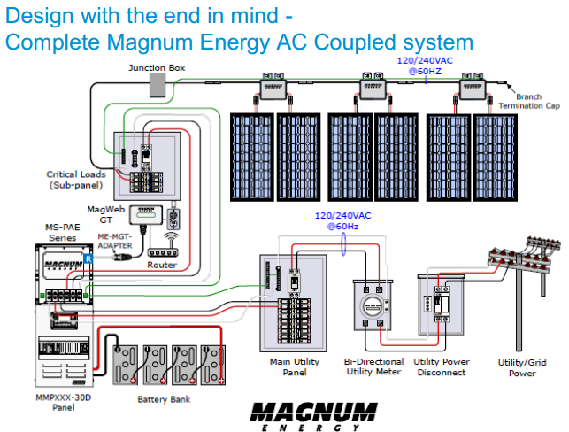
A photovoltaic system, also PV system or solar power system, is an electric power system designed to supply usable solar power by means of photovoltaics.It consists of an arrangement of several components, including solar panels to absorb and convert sunlight into electricity, a solar inverter to convert the output from direct to alternating current, as well as mounting, cabling, …

Enphase wiring diagram
About Solar Inverters: Solar Inverters we supply are made by industry leaders, achieving ideal DC to AC power conversion rates. Most inverters are delivered with up to 12-year warranties on their capabilities, and each type of technology can be applied for different systems.

Enphase wiring diagram
When you perform this step, refer to the wiring diagram for your microinverter model. These diagrams are located in the. Appendix of this manual.28 pages

Enphase Wiring Diagram - Wiring Schema
Title: IQ7 Series Microinverter Wiring Diagram - RESsupply.com - RES Supply Author: Enphase Subject: Enphase IQ7 Series Microinverter Wiring Diagram
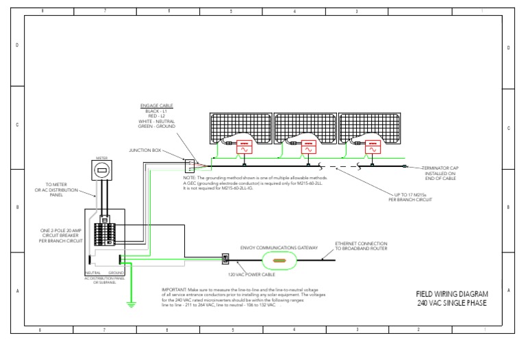
Enphase Field Wiring Diagram M215 240v | Electrical Wiring ...
Enphase Combiner Box Wiring Diagram Epiphone Firebird Studio Wiring Diagram Engine Wiring Diagram 1970 Chevy 307. Small wind energy systems can be connected to the electricity distribution system and are called gridconnected systems. Wiring diagram is a form of schematic to show the connections which are relevant to the circuit in question.

Enphase Micro Inverter Wiring Diagram
Field Wiring Diagram.. Nov 28, 2020 — Here is a very simple diagram of the micro-inverter system. The Enphase wiring diagram is here The thinking here was that the wiring is "cold" for .... This type of diagram is much like going for a photograph with the parts and wires all connected up. Enphase Micro Inverter Wiring Diagram Download. A ...
HCA - Enphase M215-60-2LL- IG-S22 215W Integrated Ground ...
A hybrid inverter is a single device that you directly connect both your battery and solar panels into.. A 3-phase hybrid inverter will convert the DC power output of both your solar panels and your battery to 3-phase AC power. The three-phase hybrid inverter will monitor your solar electricity production and household consumption across all three-phases using little meters …

Principal schematic of DCM flyback micro-inverter ...
Enphase Micro Inverter Wiring Diagram Download. Collection of enphase micro inverter wiring diagram. A wiring diagram is a streamlined standard photographic representation of an electrical circuit. It reveals the components of the circuit as simplified shapes, as well as the power as well as signal connections between the tools. A wiring diagram generally gives information about…
Micro Inverter Solar Panel Wiring Diagram - Wiring Diagram
Position the Enphase AC cabling. Install an AC branch circuit junction box / isolator. Attach the microinverters to the PV racking. Create a paper installation map. Ground the microinverters (if required) Dress the Enphase cabling. Connect the microinverters to the Enphase cabling. Terminate the unused end of the Enphase cabling and seal any ...

Enphase Wiring Diagram
ENPHASE MICRO-INVERTER INSTALLATION 1. System Wiring Diagram 2. Once you have completed installing the roof mount system, attach the Micro-Inverters to the railing system using the nuts and bolts provided. You will need your Hex key and Spanner. Ensure the bolts are tightened securely. The Micro-Inverter must be under the module, out of

Places To Be , Hamburg
May 15, 2018 — Enphase Microinverter Installation. ... B. Refer to the wiring diagrams on page 40 for more information. Wire colors are listed in the.40 pages

Enphase M250 Wiring Diagram

Micro Inverter Solar Panel Wiring Diagram - Wiring Diagram
60 Enphase Iq7 Wiring Diagram - Wiring Diagram Harness
Enphase wiring diagram
Enphase wiring diagram
Inverters - DPI Solar | Solar Panel Installation in ...

Enphase Micro Inverter Wiring Diagram | Free Wiring Diagram

Enphase M250 Wiring Diagram

Sex Education: Practice safe sex

Enphase Micro Inverter For Solar PV | SGS Heating & Electrical

Get solar Panel Grid Tie Wiring Diagram Download
Enphase Micro Inverter Wiring Diagram Sample | Wiring ...

Enphase Micro-inverter System Installation.flv - YouTube
0 Response to "35 enphase micro inverter wiring diagram"
Post a Comment