35 electric heat strips wiring diagram
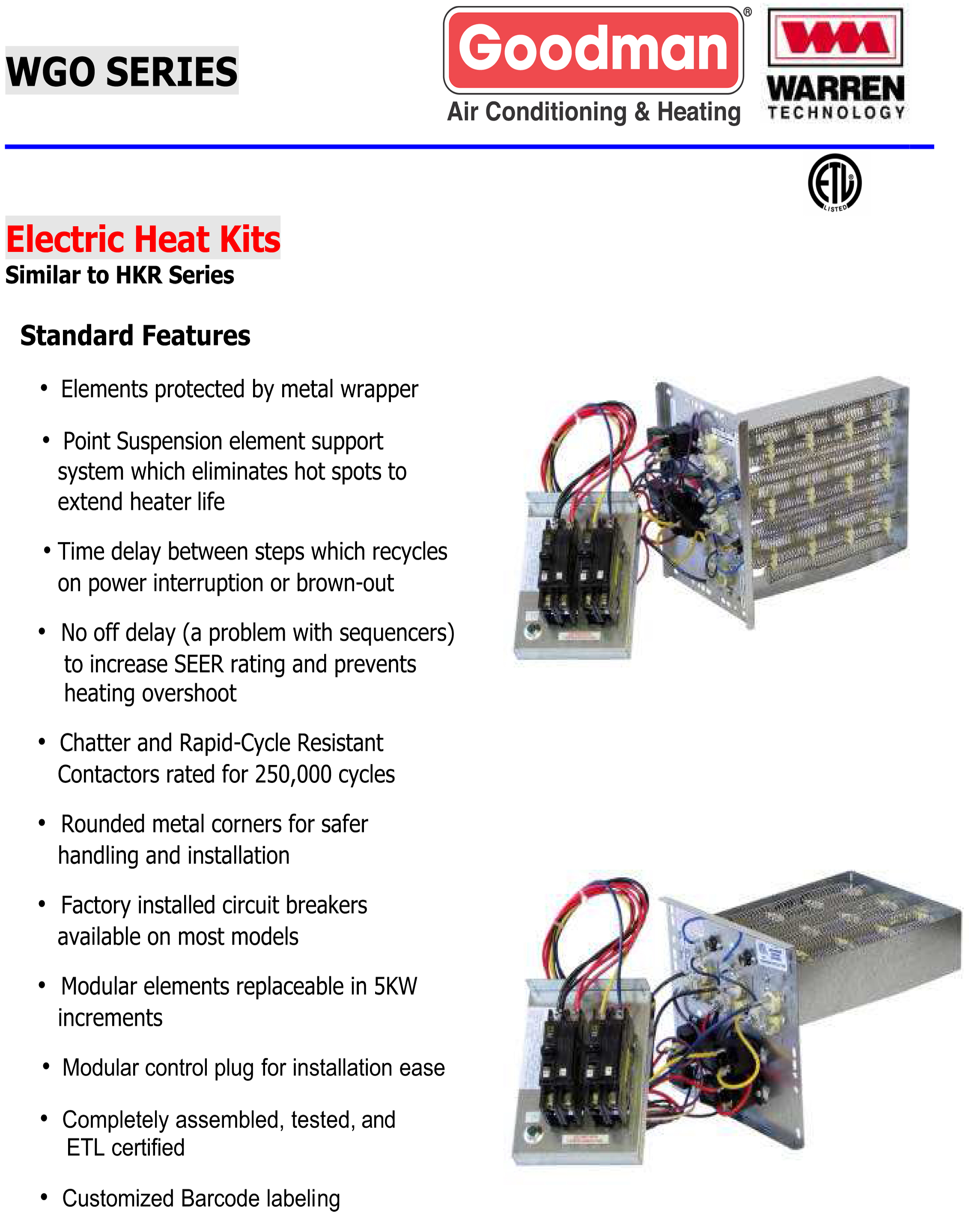
The EHWA series electric heater packages are capable of being field-installed and suitable for use with Bard wall mount air conditioners. The packages consist of the electric heat strip, the heater control base which includes the heat contactors, and circuit breaker of pull disconnects, installation instructions and wiring diagrams. are desired, cut W3 at the W2 wire nut, strip and recon-nect per wiring staging layout in Installation Instructions for fan coils. a. The 5kW, 8kW, and 10kW heaters are single stage only. b. The 9kW and 15kW heaters are adaptable for two stage operation. c.The18kW,20kW,24kW,and30kWheatersareadapt-able for three stage operation. 4.
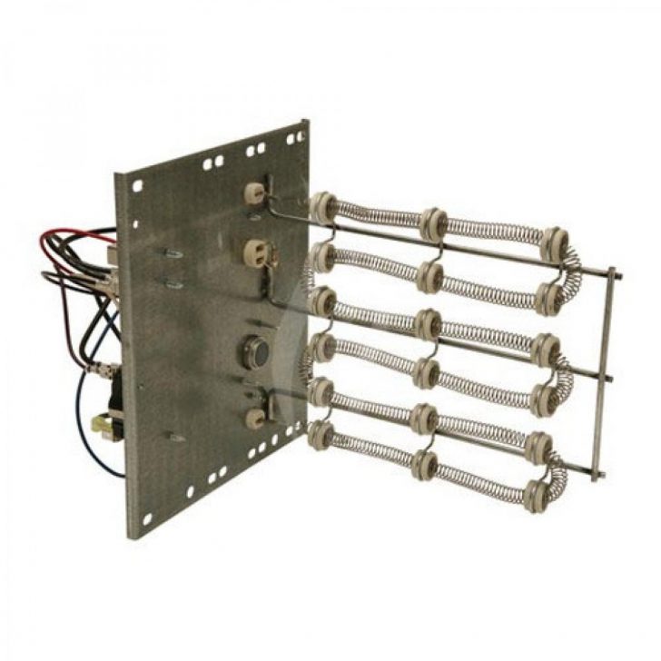
A H6HK 8kW, 10kW Electric Heat. UNPACKING ELECTRIC HEAT PACKAGE Remove the heat package from the shipping carton. The heat package must consist of the following: 1. Basic heater. 2. Electric heat control base and wiring. 3. Installation instructions. 4. Wiring diagram (2), one to be applied to unit. 5.
Electric heat strips wiring diagram
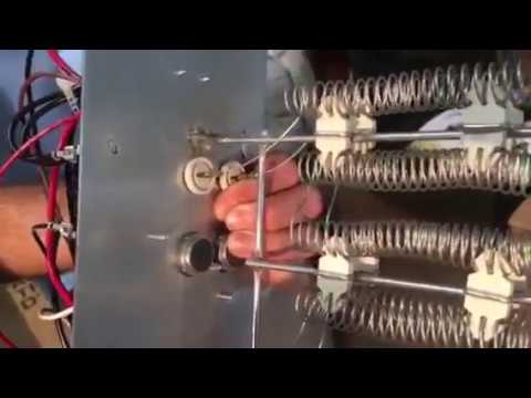
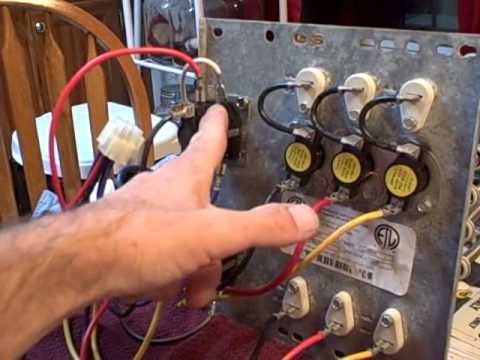
Install the wiring diagram provided with the heat kit in a prominently visible location on the exterior of the unit. 6. FOR ALL HEAT KITS: Mark an "X" on the wiring diagram according to the number of heater element rows installed. START-UP 1. Double check all electrical connections and screws to ensure proper installation. 2. Showing an electric heat kit pulled from a Goodman air handler and talking a little bit about operation and trouble shooting. I've VERY tired so apologies f... 29.07.2018 · Now imagine two paper-thin strips of different materials that are bonded together back-to-back, as you heat this up, the two strips change their length. But, if we select the right substances, one strip grows longer substantially faster than the other and this causes the bonded combination of the two to bend, to curve as one side gets longer faster than the other.
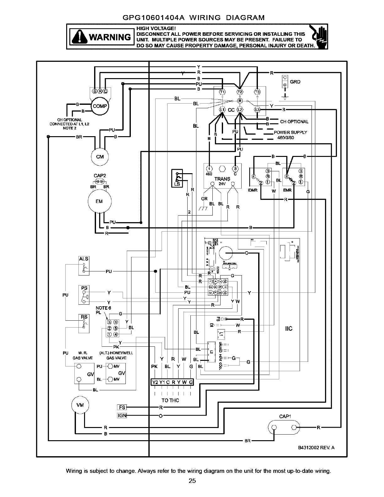
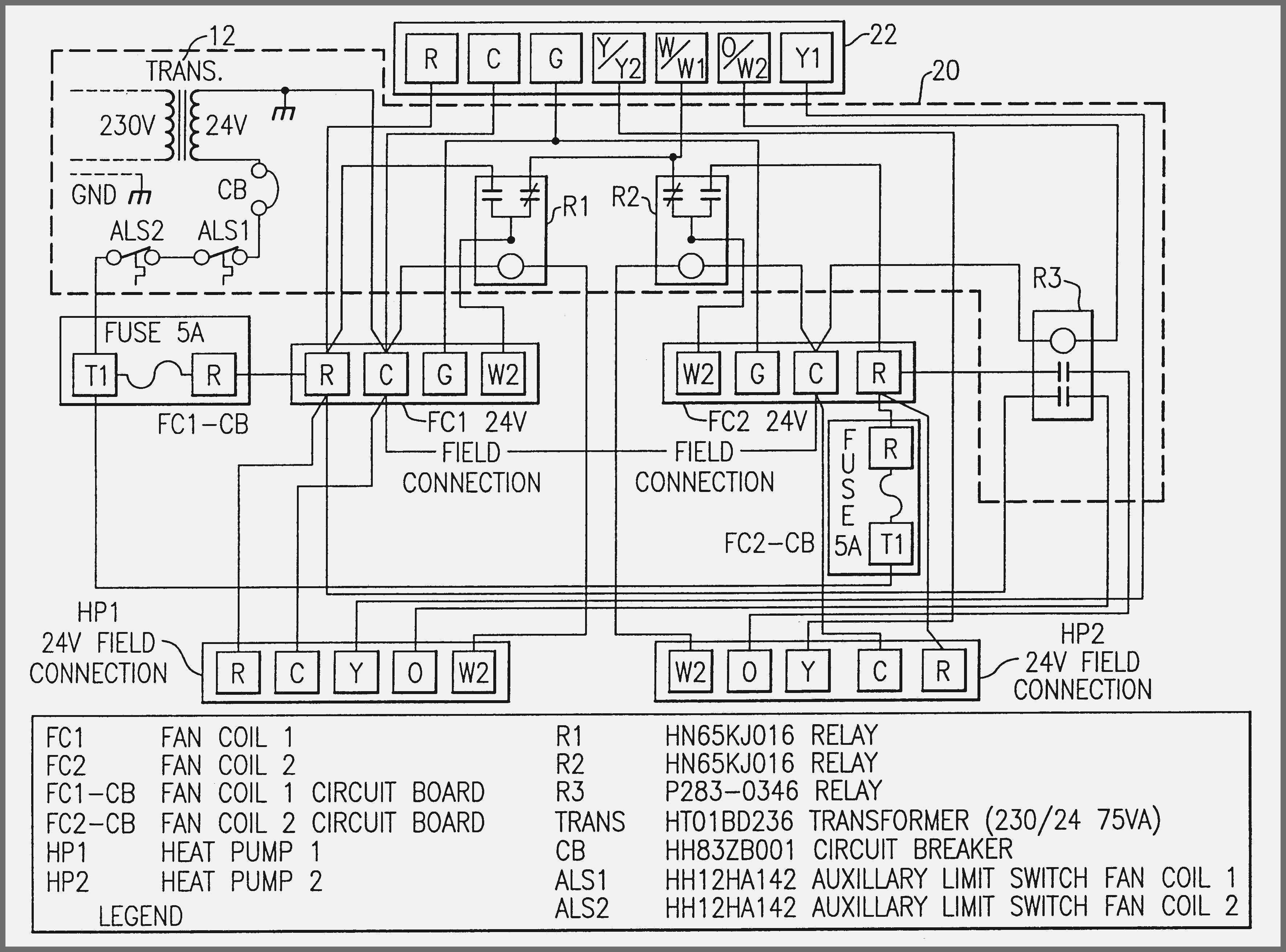
Electric heat strips wiring diagram. HEAT STRIP-3 RELAY 3 RELAY 2 BLK HEAT STRIP-2 RELAY 2 RELAY 1 BLK HEAT STRIP-1 SCHEMATIC DIAGRAM L2 NOTES: 1. Use Copper Wire (75ºc Min) Only Between Disconnect Switch And Unit. 2. To Be Wired In Accordance With Nec And Local Codes. 3. If Any Of The Original Wire, As Supplied, Must Be Replaced, Use The Same Or Equivalent Type Wire. 4. A wiring diagram is a streamlined conventional pictorial depiction of an electric circuit. A wiring diagram is a type of schematic which utilizes abstract photographic signs to show all the affiliations of components in a system. Otherwise the structure won t function as it should be. electric heat strip wiring diagram - What's Wiring Diagram? A wiring diagram is a schematic which uses abstract pictorial symbols showing every one of the interconnections of components in a system. Example of Wiring a 220 Volt Electric Heater: Identify the Voltage. 208 Volt and 220 Volt Connections Wiring connections may need to changed depending on the voltage of the unit and the voltage at the location where the unit will be installed. Electric Furnace Heating Elements and Heat Strips
Goodman 10kw Heat Strip Wiring Diagram. Dec 29, Heat Pumps and Electric Home Heating - Wiring to heat strip for heat pump system. - With my amana heat pump not wired for the 10kw emergency heat ( details The diagram I provided in that thread showed the connection. 26 - Wiring Diagram 8 kW, 10 kW, 12kW w/ X Blower Motor 11 - Grille and of Heat. HEAT STRIP--3 RELAY3 RELAY2 BLK HEAT STRIP--2 RELAY2 RELAY1 BLK HEAT STRIP--1 SCHEMATIC DIAGRAM L2 NOTES: 1. Use Copper Wire (75ºc Min) Only Between Disconnect Switch And Unit. 2. To Be Wired In Accordance With Nec And Local Codes. 3. If Any Of The Original Wire, As Supplied, Must Be Replaced, Use The Same Or Equivalent Type Wire. 4. overcurrent protection. Operating a heater at other than the specified voltage and phase can result in fire or electrical hazard. All field wiring must comply with NATIONAL ELECTRIC CODE and local code requirements. A point-to-point wiring diagram is located on the inside of the control panel door, which details wiring and field wire gauge. wattage output by 50%. Heating elements are basically in series on single phase power. R 1 R 2 I P I L V P V L Typical Heater Wiring Diagrams The following diagrams show typical heater wiring schematics. Single Phase AC circuits where line voltage and current do not exceed thermostat rating. Three Phase AC heater circuit where line voltage and
Electric heaters typically cost more to run than heat pumps, but are necessary when temperatures get so cold outside that the heat pump may not be able to keep up with the temperature. I will be explaining the basic wiring of an electric heater only today, so that those who need a little more hvac training on the subject can do so here. Buy Screwdrivers & keys at B&Q - 90 day returns 300 stores nationwide inspiration for your home & garden products reviewed by customers Wiring Diagrams. A specific wiring diagram for each heater including all controls is glued to the inside of the control panel door. Another wiring diagram is provided loose in the control box. Heater Element Rack Replacement For Series Fan Powered Terminal Units. On series fan Powered Terminal Units, the element rack is removable for replacement. 9. Wire heater package per wiring diagram supplied with this heater package. All wires are stamped with wire numbers that correspond with terminal numbers on the wiring diagram and stamped numbers on the heat strip. Limit switch wires are terminated with insulated quick connect terminals. See Figure 4. WARNING Disconnect all power to unit ...
5 Kw Rheem Rxbh Electric Strip Heater With Circuit Breaker ...
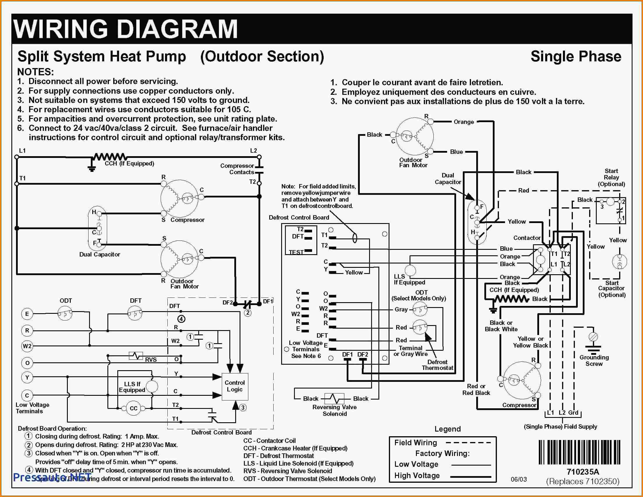
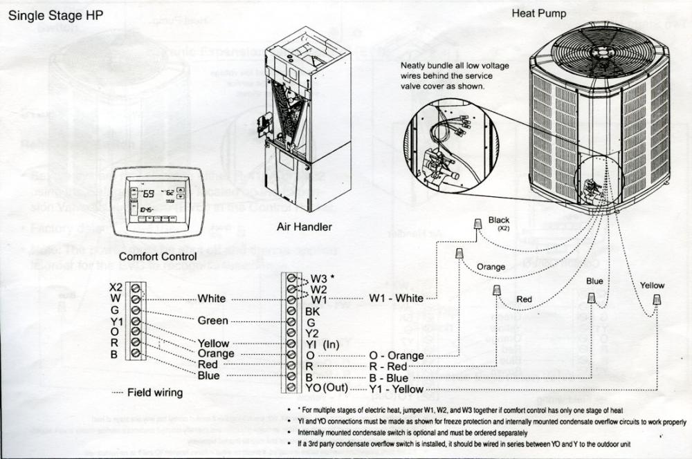
Thermostat Wiring Diagrams for Heat Pumps - Heat Pump Thermostat Wire Diagrams. Heat pumps are different than air conditioners because a heat pump uses the process of refrigeration to heat and cool.While an air conditioner uses the process of refrigeration to only cool, the central air conditioner will usually be paired with a gas furnace, an electric furnace, or some other …

DIY Mobile Home Repair: Mobile Home Electric Furnace ...
I just purchased a home and all the wires for the heat strip are taken off and laying in the air handler. i tested the heat strips by jumping 120 to them, the relay is good also. but there's no wiring diagram. its a double strip hrk 10. m# on the air handler is ARUF303016BA s# is 1002505621. if someone could shoot a pic or post a diagram id be greatful. thank you in advance. its a 2005 model.

Electric Heat Strip Wiring Diagram - easywiring
Insert the one provided in the electric heat kit. It can be in-serted in one position only. 11. Insert the ground wire into the lug(s) provided for that pur-pose. 12. Break out the appropriate area of the electric heat kit cover, previously removed for the circuit breaker provided in the heater kit. See Step 3. 13. Replace electric heat kit cover.
Goodman Heat Strip Wiring Diagram : 220 Volt Electric ...
Harness contains both 24--v control and high--voltage wiring. Blower power is provided through heater harness. NOTE: Units with or without electric heaters ...10 pages
Electric Heat Strip Wiring Diagram - MORPHINE-AND-DRUGS
www.supercoolsliderule.com -- This video tutorial will illustrate with a wiring schematic and photos how an electric heater operates. Some troubleshooting wi...

I have a Nordyne air handler, model B3BV-030K-AB. The heat ...
FAN COILS. ACCESSORY ELECTRIC HEATERS. WIRING DIAGRAMS ... Cooling controls wiring not used with electric heaters. ... LS1 HEAT STRIP-1.32 pages
Nordyne Wiring Diagram Electric Furnace Collection ...
(See diagram 1.) The photovoltaic effect is a process by which light from the sun hits a solar cell and is absorbed by a semiconducting material such as crystalline silicon. The photons in the sunlight knock electrons loose from their atoms, allowing them to flow freely through the material to produce direct electric current (DC) electricity ...
10 KW heat strip for Goodman units GPH, GPC, AR, AER, ADP ...
Aug 28, 2012 · It is a 6 wire system 1 cool 2 heat (heat strips) . A/C – and fan in air handler worked perfectly fine but only had aux. heat. Well I cut all power and double checked the tstat wiring and found nothing to be wrong. I reattached the wire have and face unit and now nothing is working , no condenser , no air handler fan nor aux heat.

I bought a 15 KW heat strip for Carrier/Bryant/Payne heat ...
Page 128 ® VISIONPRO 8000 WITH REDLINK™ THERMOSTAT/EIM TO THERMOSTAT AIR HANDLER HEAT PUMP HEAT PUMP AUX1 AUX2 M31487 Wood stove with heat pump and backup electric strips. (For applications in which the thermostat only needs to run the blower fan when stove is hot). 1 Select Geothermal Radiant Heat at ISU 201.

Electric Heat Strip Wiring Diagram - MORPHINE-AND-DRUGS
15kw intertherm electric furnace wiring diagram. electric furnace has two 60 amp two pole brkskw heat strips. one 60 has two wires from the load side each pole (four total). the other 60 brk.Feb 04, · We roughed in the wiring for a residential electric furnace today and the furnace nameplate data has me wondering. ...

Electric Heat Strip Wiring Diagram - easywiring
05.11.2021 · Install a 2 wire cable between the power source (outlet box, electric panel, etc) and the first switch box. Leave 8–10 inches (20.3–25.4 cm) of wire inside both boxes (source and first switch) before cutting the cable to facilitate easy connection to the switch and power source. Connect the ground wire to the circuit ground wire(s) with a wire nut or other approved …

Electric Heat Strip Wiring Diagram Nice York Heat Strips ...
installation of Accessory Electric Heaters into the Split System Heat Pump and Cooling Unit air handlers. Unit-to-heater matchup is described in Table 1 and Table 2. 2. These Air Handlers and Heaters are designed so that all Class I (high voltage) wiring between the heater and unit is accomplished by the method of hard wiring. Class II wiring (low
Electric Heat Strip Wiring Diagram | Cadician's Blog
Auxilliary Heat Strips For Trane Tam7ab30h21 Wiring Diagram. Unless I'm missing something in your explanation, using the 2/0 AL wire doesn't seem to be a problem, except that it's AL and the unit does not. 47 results Heat strips that replace most Trane air handlers and package units. These replacement electric heat strips fit your unit exactly.
HVAC Electric heat kit / strips shown! - YouTube
Wiring Diagram Images Detail. Goodman heat pump package unit wiring diagram Electric Heat Strip Wiring Diagram Beautiful Goodman Air Handler Ac Center E280a2 4. Low voltage is the voltage that is used to control the unit from a thermostat or other Single phase will be two power wires and a ground three phase will be the thermostat.

I have a Nordyne/Intertherm Model E2EB015HB Electric ...
Connect heater wiring harness plug to receptacle on fan control board or wire harness. ... stages are desired, cut W3 at the W2 wire nut, strip and.14 pages

Goodman fan and heat strips run constantly - DoItYourself ...
installation of Accessory Electric Heaters into the Split System Heat Pump and Cooling Unit air handlers. Unit-to-heater matchup is described in Table 1 and Table 2 . 2. These Air Handlers and Heaters are designed so that all Class I (high voltage) wiring between the heater and unit is accomplished by the method of hard wiring. Class II wiring (low

Goodman Heat Strip Wiring Diagram : 220 Volt Electric ...
Heat Pumps and Electric Home Heating - goodman heat strip wiring - I bought a hkr-10c heat strip to replace an old one that stopped working. The wiring has a 9 prong plug but the unit has 6 prong wiring. Anyone have a diagram or know the correct wiring?

Goodman Heat Strip Wiring Diagram - Humidaire 3i Heated ...
Heat Pump Thermostat Wiring Chart. That is for use for heat pumps.You should 100% make sure that you have a heat pump system and not an air conditioner with electric heating strips as it is a common mistake for people to misidentify their HVAC systems.

Hkr 15c Wiring Diagram
27.05.2021 · But people often take electrical wiring harness, loom, cable assembly, wiring assembly, coax cable, RF ... them up correctly, you’ll need these 5 things: 1) The wires of various types required by the circuit; 2) A schematic diagram showing how everything should connect together; 3) Electrical conductors (usually copper); 4 ) Insulation on electric power circuits;5). …

Goodman Heat Pump Wiring Diagrams / Goodman Electric Heat ...
Jun 08, 2021 · W/B: The W/B terminal controls the heat relay or valve. When the thermostat calls for heat, a signal is sent to power up the furnace and the blower fan or the boiler, heating your home. Y1: The Y1 terminal is used for the compressor contact in a single-stage heat pump installation.
Electric Heat Strip Wiring Diagram - When I put my Furnace ...
of open coil and finned tubular duct heaters within minutes. With this software, your local INDEECO representative becomes the source for certified prints, wiring diagrams — complete submittal information. Our heaters and controls range from the simplest standard duct heater to the most sophisticated, custom designed comprehensive system.

Heat Pump blows cold air - DoItYourself.com Community Forums
wiring diagram fig. 5 - 20kw electric duct heater wiring diagram 260 north elm street westfield, ma 01085 (413) 568-9571 • fax (413) 568-9613 7555 tranmere drive mississauga, ontario l5s 1l4 canada (905) 670-5888 • fax (905) 670-5782 fig. 3 - 10kw electric duct heater wiring diagram.
![[DIAGRAM] Goodman Heat Strip Wiring Diagram FULL Version ...](https://f01.justanswer.com/JACUSTOMER2gh72lm8/2012-12-04_005710_2012-12-03_19.49.24.jpg)
[DIAGRAM] Goodman Heat Strip Wiring Diagram FULL Version ...
Apr 20, 2021 · For this reason, cable assemblies can shield the interior wires and cables from heat, extreme heat, friction, moisture, abrasion, compression, and other hazards. But people often take electrical wiring harness, loom, cable assembly, wiring assembly, coax cable, RF cable, injection-molded cable assembly, fiber optic cable, cable harness as one ...

Wiring to heat strip for heat pump system. - DoItYourself ...
DOWNLOAD. Wiring Diagram Images Detail: Name: electric heat furnace wiring diagram - Dayton Baseboard Heater Wiring Diagram Valid New Payne Electric Furnace Wiring Diagram. File Type: JPG. Source: rccarsusa.com. Size: 1.27 MB. Dimension: 2136 x 1584. READ Schneider Electric Contactor Wiring Diagram Sample. DOWNLOAD.

Heat won't turn off on Goodman ARUF-030-00A-1 ...
Most manufacturers provide wiring terminal strips with the appropriate letter designations to aid in wiring. Strip 1/4 inch of insulation from each wire with the wire strippers. Secure each wire to the appropriate screw terminal with the screwdriver. Test the heat pump and strip heat in all modes after installation to ensure proper operation.

Electric Heat Strip Wiring Diagram Collection
Often this is a direct result of a dead short in the wiring Call for service. Ice or Freezing: 1) Ice or freezing of the condensing unit can be because of a problem with the defrost cycle. The quickest way to solve this problem and get heat is to turn the thermostat to air conditioning mode. When the ice is gone turn the thermostat back to heating mode. Then call for service. 2) Ensure there ...

Electric Heat Strip Wiring Diagram Popular Wiring A Heat ...
20% off orders over $120* + Free Ground Shipping** Online Ship-To-Home Items Only. Use Code: JANSAVINGS

Goodman Heat Strip Wiring Diagram - Humidaire 3i Heated ...
Electric heat accessory kits (PHK-) can be ordered for field installation ... Low voltage control wiring are terminal strip or pigtail leads ... 240V terminal to 208V terminal as shown on the wiring diagram. Use only copper conductors. If any of the original unit wiring is replaced, the same size ...
34 Goodman Electric Furnace Wiring Diagram - Wiring ...
Newsletter sign up. Take A Sneak Peak At The Movies Coming Out This Week (8/12) Why Your New Year’s Resolution Should Be To Go To The Movies More
![[RN_2523] Air Handler Electrical Wiring Download Diagram](https://static-resources.imageservice.cloud/1469414/15kw-air-handler-wiring-diagram-wiring-schematic-diagram-198.jpg)
[RN_2523] Air Handler Electrical Wiring Download Diagram
29.07.2018 · Now imagine two paper-thin strips of different materials that are bonded together back-to-back, as you heat this up, the two strips change their length. But, if we select the right substances, one strip grows longer substantially faster than the other and this causes the bonded combination of the two to bend, to curve as one side gets longer faster than the other.

Electric Heat Strip Wiring Diagram Download
Showing an electric heat kit pulled from a Goodman air handler and talking a little bit about operation and trouble shooting. I've VERY tired so apologies f...
Electric Heat Strips Wiring Diagram / Goodman 10kw Heat ...
Install the wiring diagram provided with the heat kit in a prominently visible location on the exterior of the unit. 6. FOR ALL HEAT KITS: Mark an "X" on the wiring diagram according to the number of heater element rows installed. START-UP 1. Double check all electrical connections and screws to ensure proper installation. 2.

Trying to wire a honeywell 8320 thermostat to ruud ...

Goodman Electric Heat Strip Wiring - HVAC - DIY Chatroom ...

I have a goodman CPKJ36 heat pump with emergency heat ...
0 Response to "35 electric heat strips wiring diagram"
Post a Comment