38 stinger capacitor wiring diagram
September 8, 2021 on Single Phase Motor Wiring Diagram With Capacitor. These instructions will probably be easy to comprehend and implement. It uses a single pole double throw type transfer switch to impress a high voltage across the capacitor during start up. Wiring Diagram For Capacitor Start Motor Techunick Biz Capacitors Motor Pioneer Radio.
Single Phase Capacitor Start Motor Wiring Diagram from i.stack.imgur.com. Print the wiring diagram off plus use highlighters to trace the signal. When you make use of your finger or perhaps the actual circuit with your eyes, it is easy to mistrace the circuit. 1 trick that We 2 to printing a similar wiring plan off twice.
12+ Ceiling Fan Capacitor Wiring Diagram. Sistemas de arranque de compresores en refrigeracion 120 vac y 220 vac en general. Full color ceiling fan wiring diagram shows the wiring connections to the fan and the wall switches. We must connect the capacitor in series with the starting winding and then it connected across the power supply.

Stinger capacitor wiring diagram
Multiple Capacitor Wiring Diagram Warning Limited Manualzz. Stinger Car Audio Capacitors. Stinger Spc5010 10 Farad Pro Digital Hybrid Capacitor. Stinger Spc5010. Stinger Select Sscap2m Brushed Aluminum 2 Farad Digital Capacitor 5000w. Stinger Spc505 Pro Hybrid 5 Farad Capacitor Com. Amplifier Wiring Diagrams How To Add An Your Car Audio System.
baldor motor capacitor wiring diagram - What is a Wiring Diagram? A wiring diagram is a simple visual representation from the physical connections and physical layout associated with an electrical system or circuit.
1Ø WIRING DIAGRAM Diagram ER4 1Ø WIRING DIAGRAMS M 1~ LNE 3 active wires plus auto-reset thermal contacts Codes: CE19.. to CE28.. + other fans as shown Brown Black Blue M 1~ Green/Y ellow Brown Cap Black CE31 only Single phase AC motor with capacitor Blue or Grey A N SILDES These diagrams mainly apply to EXTERNAL ROTOR MOTORSbut some standard ...
Stinger capacitor wiring diagram.
Capacitor Motor Single-Phase Wiring Diagrams ALWAYS USE WIRING DIAGRAM SUPPLIED ON MOTOR NAMEPLATE. W2 CJ2 UI VI WI W2 CJ2 UI VI WI A cow VOLTAGE Y HIGH VOLTAGE z T4 Til T12 10 Til T4 T5 ALI L2 T12 TI-BLU T2-WHT T3.ORG T4-YEL T5-BLK T6-GRY T7-PNK T8-RED T9-BRK RED TIO-CURRY TII-GRN T12-VLT z T4 Til T12
Note: each wiring diagram is shown with a treble bleed modification (a 220kΩ resistor in parallel with a 470pF cap) added to the volume pots. ES-335 Prewired Standard Assembly P-GMOD-6. Connect your neck pickup to the pigtail labeled "N" and your bridge pickup to the pigtail labeled "B".
How to wire single phase motor with capacitor. There are two capacitors in this method one is used at the time of the starting and is known as starting capacitor. Electric Motor Wiring Diagram Single Phase Basic Electronics Capacitor start capacitor run induction motors are single phase induction motors that have a capacitor in the […]
Capacitors Faq What S A Capacitor And Does It Do. How to install car audio capacitors capacitor installation a installing energy storage s learn sparkfun com electric motor starting series and parallel hvac run quality wiring diagram for 1 2 amps table fan directly power plug factor correction kvar charged light an led bank modes alpes start explained faq what hard kit dual reactive ...
Single Phase Motor Wiring Diagram With Capacitor Video Parallel connection is much more complicated than the string one. Unlike in series connection, the voltage of every part is comparable. It is because the element is directly linked to electricity resource. This circuit consists of branches that are passed by distinct electric current amounts.
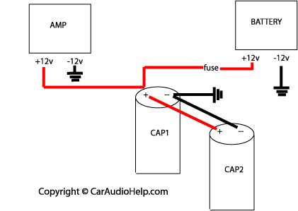
A diagram for the capacitor charging setup is shown below. You will need to place a voltmeter across the capacitor to monitor the voltage. Once the voltmeter reads 12 volts (or close to it) you can remove the voltmeter and replace the resistor with the power fuse.
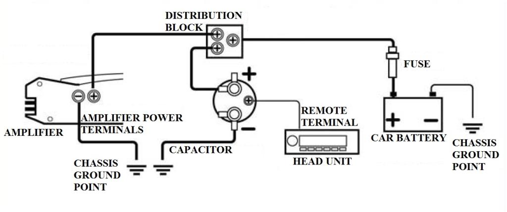
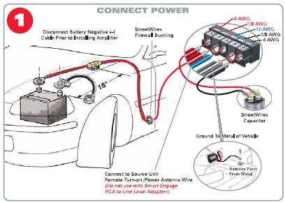
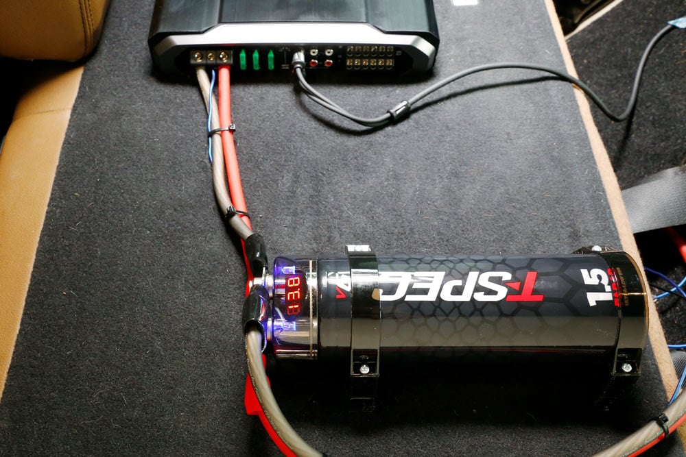
Connect the remote turn on wire. If your capacitor has an internal meter, it will also have a third wire. This is the remote turn on wire and serves to kill power to the meter whenever the car is turned off. You will need to wire this into the remote turn on wire into any 12 volt switched power source (such as the ignition switch or amplifier).
Please visit our website: http://www.onecapacitor.com/Lishui Topo Electronic Co.,Ltd is leading capacitor manufacturer in China, is established in 2009, incl...
Capacitor Start Motors Diagram Explanation Of How A Is To Single Phase Motor Bright Hub Engineering. Single phase cap start run motors electric motor starting capacitor and capacitors madcomics wiring diagram dual fig 13 connection explained electrical for a csir ac cost replacement to quality baldor vl1309 air compressor kulthorn split hermetic windings fixed ffre1233s1 frigidaire window the ...
Power and speaker wire for your high performance car audio installation. CONSTRUCTED FROM PURE 100% VIRGIN COPPER Stinger's power and speaker wire is made of True-Spec, tinned, oxygen-free copper for oxidation prevention, making Stinger one of the best conductors.
Stinger Capacitor Wiring Diagram - wiring diagram is a simplified allright pictorial representation of an electrical circuit. It shows the components of the circuit as simplified shapes, and the aptitude and signal connections with the devices. Car Sound Capacitor
Stinger Capacitor Wiring Diagram from i.ytimg.com Print the electrical wiring diagram off in addition to use highlighters in order to trace the circuit. When you make use of your finger or perhaps stick to the circuit together with your eyes, it is easy to mistrace the circuit. 1 trick that I use is to print a similar wiring plan off twice.
Pkg stinger spc505 5 farad capacitor & 0 gauge ga amp wire install amplifier kit | ebay
Available in Power and Complete (power + signal) Kits, Stinger's Wiring kits have all the essentials for a professional installation. Featuring 100% oxygen-free tinned copper for a pure, uninterrupted transfer of power. Tru-spec cables/wires meet or exceed the industry standard of copper required for the gauge size.

Stinger sscap2m carbon fiber 2 farad digital capacitor
As i shown in the above ceiling an 3 wire capacitor diagram that red is common wire and yellow for microfarad and Purple for farad. However IN SHA ALLAH in further post i will explain the fan 5 wire capacitor, regulating speed switch diagram and replacement of fan capacitor in fan motor. Dec 28, · Generic 3-speed reversible spinner wiring diagram.

Buy soundbox 4 gauge amp kit amplifier install wiring & 2.5 ...
Below is also a typical wire diagram for connecting a capacitor so you can reference my notes above. Click below to view our selection of: 1 Farad Capacitors - 2 Farad Capacitors (and higher) - Hybrid Capacitors. Popular capacitor brands include: Stinger Capacitors - Sound Quest Capacitors - Power Acoustik Capacitors
How to install a car audio capacitor in your vehicle
DOWNLOAD Wiring Diagrams Free. Close DOWNLOAD. 1986 Honda Goldwing Aspencade Wiring Diagram. More Details . Dyt 4000 Belt Diagram. More Details . ... Stinger Capacitor Wiring Diagram. More Details . Dynamic Mic Xlr Wiring Diagram. More Details . Airtex Fuel Pump Wiring Diagram. More Details . Centurylink Prism Wiring.

Stinger car audio capacitors
Installing A 5-2-1 Hard Start Capacitor Kit On A Tempstar/carrier - Motor Run Capacitor Wiring Diagram. Wiring Diagram not merely offers comprehensive illustrations of everything you can perform, but also the processes you ought to adhere to whilst performing so. Not only can you discover different diagrams, but you can also get step-by-step ...

Details about stinger spc505 new 5 farad digital pro hybrid power car audio capacitor spc-505
campervan split charge wiring diagram; capacitor 220v single phase motor wiring diagram; capacitor compressor wiring diagram single phase; capacitor reversing single phase motor wiring diagram; capacitor single phase motor starter wiring diagram; capacitor start 220v single phase motor wiring diagram; capacitor start single phase motor wiring
Boss audio systems cpbk2-2 farad car capacitor for energy ...
Capacitor Wiring Diagram Single Run Capacitor Wiring Diagram . The graphic is a reproduction of a Fasco motor. It is basically self-explanatory. The only thing missing from this graphic is the motor rotation wiring which is a yellow and a purple wire that will reverse the direction of the motor depending on

Stinger sckh1 car audio 1 farad capacitor cap with install kit
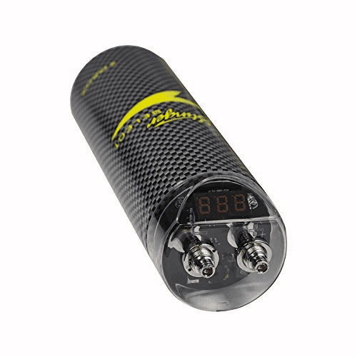
Digital 5 Farad Hybrid Capacitor. 5 farad capacitor for systems up to 1000 Watts. Bright red LED voltage display. performs similar to a capacitor/battery combo. Louder and cleaner bass response. Monitor system voltage. 12-16 volt operation / 18 volt surge. Uses screw terminals for use with 0/4 gauge of power/ground cable.

Stinger spc5010
240 Vac Motor Wiring - Wiring Diagrams Hubs - Single Phase Motor Wiring Diagram With Capacitor. Wiring Diagram will come with numerous easy to follow Wiring Diagram Directions. It is intended to help all the typical user in building a correct program. These instructions will probably be easy to comprehend and implement.

Stinger spc5010 capacitor 10farad 18v 2000w
Capacitor Wiring Diagram For Electric Motor from i.pinimg.com. Effectively read a wiring diagram, one offers to find out how typically the components within the method operate. For example , if a module is powered up also it sends out the signal of 50 percent the voltage and the technician will not know this, he would think he provides an issue ...

Stinger spc505 pro hybrid 5 farad capacitor
Start capacitor wiring diagram. Push the wire terminal on the start capacitor s second wire onto the run capacitor s common terminal often labeled c com the wire connected to the motor s run terminal marked as r on the motor s wiring chart and the wire going to the hot terminal on the load side of the contactor also connects to this run ...

5 farad capacitor stinger digital led volt meter 1000 watts spc505 hybrid pro 5 farad capacitor stinger digital led volt meter 1000 watts spc505 ...
Amplifier wiring diagrams: how to add an amplifier to your ...
How to properly install stiffening cap? | mazda 6 forums

How to install a car audio capacitor
Capacitor wiring
Stinger spc5010 10 farad pro digital hybrid capacitor

How to install a capacitor (with pictures) - wikihow

Installing a car audio capacitor with rem terminal

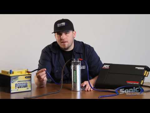
How to install car audio capacitors - sonic electronix ...

Stinger spc5010 10 farad pro digital hybrid capacitor

Kevin new (knew08380) - profile | pinterest
Capacitors faq — what's a capacitor and what does it do?

✓ how to connect a car sound capacitor
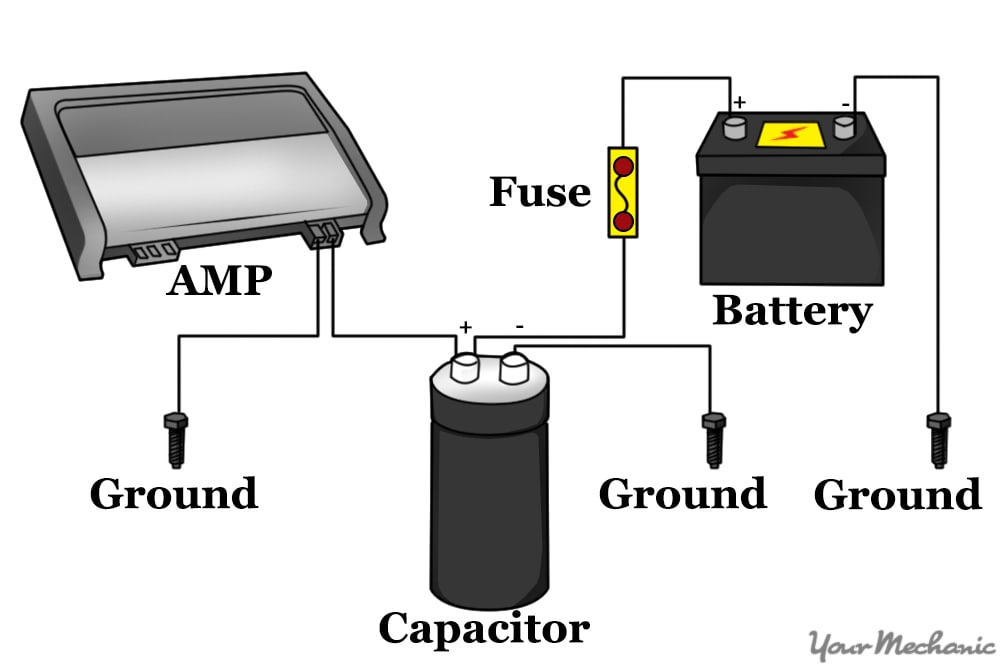
How to install a capacitor | yourmechanic advice

Digital hybrid capacitor 5 farads – stinger electronics

✓ how to install a stiffening capacitor

Amazon.com: stinger spc5010 pro hybrid 10 farad capacitor ...

How to charge a capacitor - sonic electronix learning center ...

Multiple capacitor wiring diagram: warning!! limited | manualzz
Suneducationgroup.com stinger sscap2m 2 farad 2000 watts car ...

Car audio capacitor installation

10 farad capacitor stinger digital led volt meter 2000 watts spc5010 hybrid pro
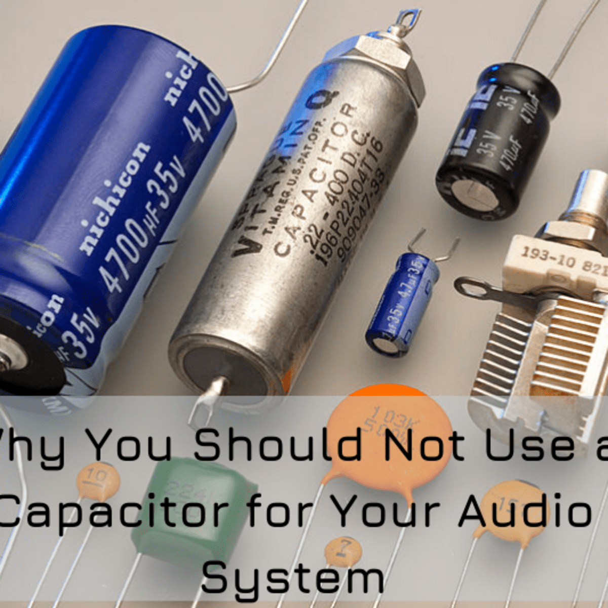
Why car audio capacitors don't work - axleaddict

16+ crossover wiring diagram car audio - car diagram ...
Car audio capacitor installation

✓ lightning audio bolt 1 farad capacitor
0 Response to "38 stinger capacitor wiring diagram"
Post a Comment