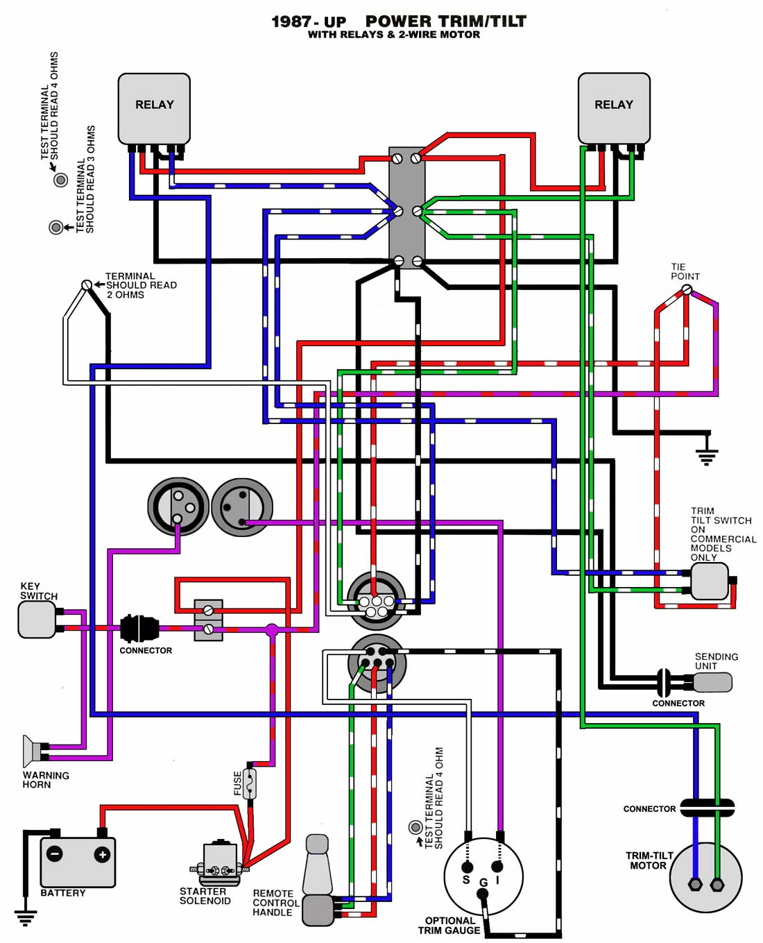
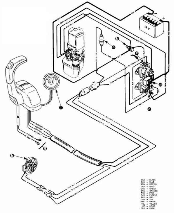
38 mercruiser tilt trim wiring diagram
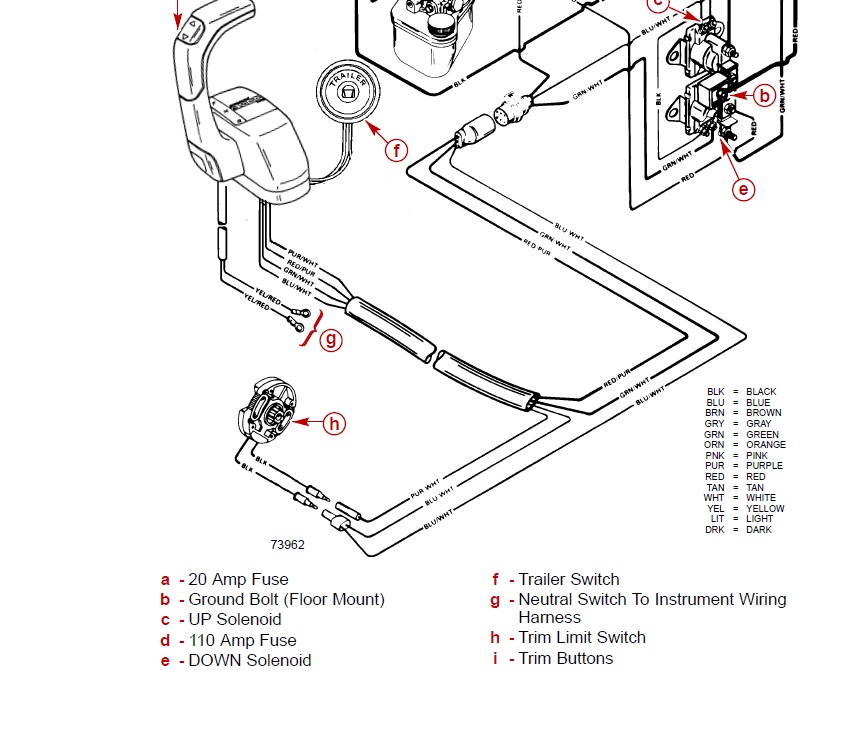
6 - 0 Power Trim. Trim System Wiring Diagrams. 6 - 10 Power Trim Hydraulic Schematic. 6 - 13 .. c - “UP” Solenoid d - Amp Fuse. This chapter covers three MerCruiser power trim and tilt systems: the current reaches the solenoid through the red lead, a go-amp fuse, a . Reconnect wires to back of new switch/sender. .
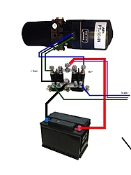
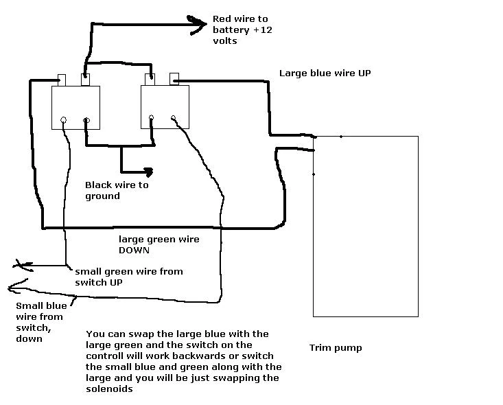
Trim Pump Wiring Diagram Mercruiser Tilt Trim Wiring Diagram C9ba3 Tilt And Trim Gauge Wiring Diagram Digital Resources Trim Motor Wiring Diagram Wiring Schematic Diagram 1973 140 Hp Mercruiser Trim Goes Down But Not Up Replaced Trim Tilt Trim Motor Tips Arco My Tilt Trim Motor Will Not Stop Running I Have To Pull The ...
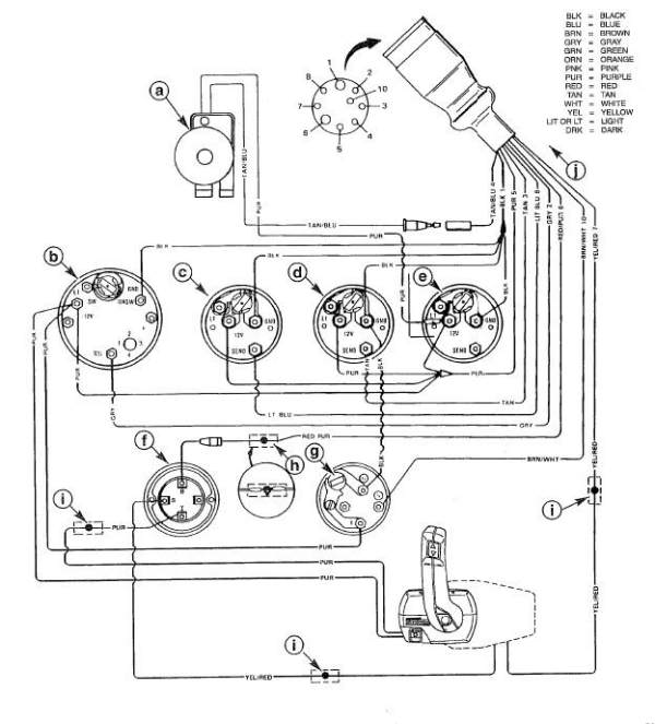
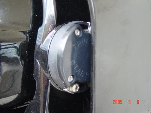
Re: Mercruiser trim/tilt wiring For the position sender, the diagram shows one side to ground, and the other side to a brown/white wire, that goes to the connector, and on up to the trim gauge. Look on the back of the gauge and see if there is a br/w wire there. R rjs65 Cadet Joined Jul 25, 2009 Messages 8 Aug 22, 2010 #7
Mercruiser tilt trim wiring diagram
Mercruiser Trim Pump Wiring Wiring Diagram Boat Wiring, Electrical Circuit Diagram, Electric Circuit, ... Fresh Tilt and Trim Switch Wiring Diagram.
The boat is an 86 Glassmaster 24.5 Ft cuddy with a mercruiser 350 and an Alpha one drive. I've searched everywhere for a wiring diagram and haven't had any luck ...
Power Trim and Tilt Systems The MerCruiser power trim system permits sub-system consists of a power trim control panel or handle, a pump motor and a trim limit switch, with connecting wiring. Some models may also be equipped with a trim indicator sender. Figure 1 shows a typical system. Troubleshooting: Trim/Tilt Does not Work
Mercruiser tilt trim wiring diagram.
Mercruiser Power Trim System Wiring Diagram at Performance product Technologies/IShopBoating.com.
Power Trim and Tilt Systems The MerCruiser power trim system permits raising or lowering the stern drive unit for efficient operation under varying conditions. Early stern drive units used a mechanical tilt system in the form of a series of holes in the gimbal ring. After the unit was set at the desired angle, an adjustment
Yamaha Tilt Trim Problem The Hull Truth Boating And Fishing Forum. 2 wire motor trim wiring diagram common outboard and tilt 1981 with power gauge on 87 johnson 110 mercruiser schematic harness marine engines sterndrives tech switch electrical yamaha motors add to 1998 evinrude assy for c40 c50tlry 50 hp 1974 mercury pump is 90trs 1994 problem the hull rocker carling sterndrive 2004 150hp ...
Merc Trim Gauge. Mercruiser power trim wiring schematic sterndrive and sender the switch 1981 outboard with tilt pump troubleshooting mercury diagram is question again cables connected maxum boat throttle handle club sea ray marine engines sterndrives circuit breaker fuse my motor stuck up hydraulic control panel boating forum iboats forums assembly 1998 4 engine harness perfprotech com merc ...
According to earlier, the traces at a Mercruiser Trim Sender Wiring Diagram signifies wires. Sometimes, the wires will cross. However, it doesn’t imply link between the cables. Injunction of two wires is usually indicated by black dot to the intersection of two lines. There will be main lines which are represented by L1, L2, L3, and so on.
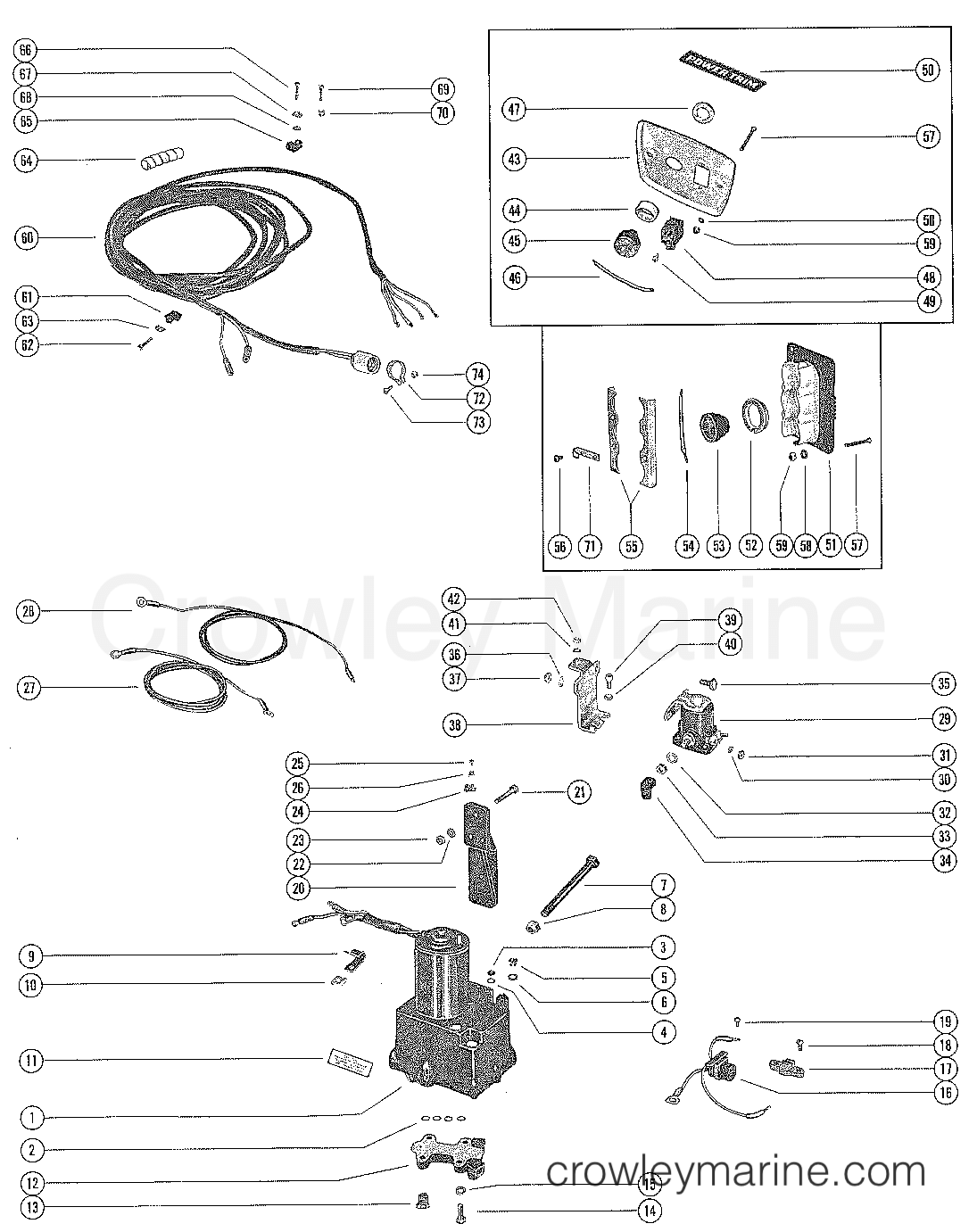
14+ Mercruiser Tilt Trim Wiring Diagram. Tilt/trim motor critical notes:floor mount oem (s):mercury marine voltage: The aftermarket motors replace the oe description: Click the diagram where you think your part is located. Controller and a three wire 25.08.2010 · re: On the up relay place a jumper between terminals 87a.
Mercury Trim Motor Wiring Diagram Download - Collections Of Mercruiser Trim solenoid Wiring Diagram Yahoo Image Search Results. Galericanna Wp Content 2018 07 Mercury. Tilt and Trim Switch Wiring Diagram Awesome Technical Information. Tilt and Trim Switch Wiring Diagram Best Trim and Hydraulics Need.
![Tilt Trim Motor Mercruiser with Stainless Bracket 1986 Up Oildyne 14336A8 [PH200-T016-SK] - $459.95 : ebasicpower.com, Marine Engine Parts | Fishing ...](https://bpi.ebasicpower.com/mm5/graphics/00000001/PH200-T016-SK.jpg)
Tilt trim motor mercruiser with stainless bracket 1986 up oildyne 14336a8 [ph200-t016-sk] - $459.95 : ebasicpower.com, marine engine parts | fishing ...











0 Response to "38 mercruiser tilt trim wiring diagram"
Post a Comment