36 garage door sensor wiring diagram
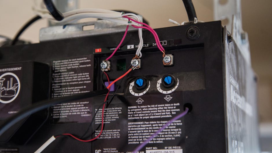
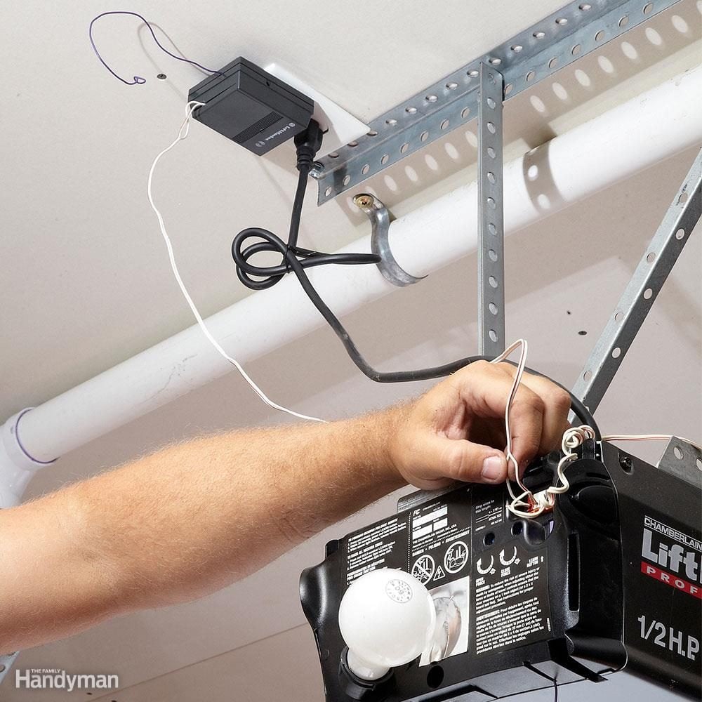
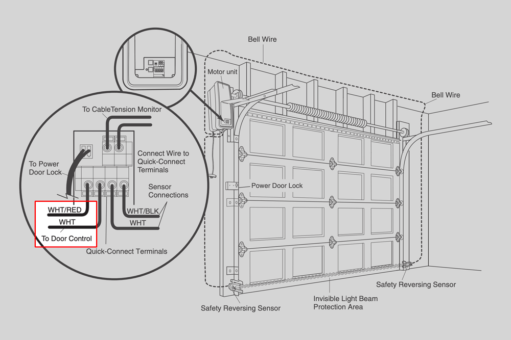
Bend the ends of the wire into small hooks. Slide the two wires with the black stripe on one of the terminal screws and tighten the screw. Slide the remaining two solid white wires on the remaining terminal screw and tighten the screw. Plug the opener power cord into the ceiling outlet. Kenneth Crawford
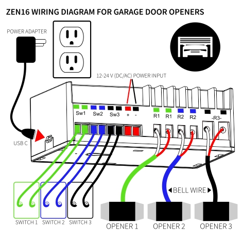
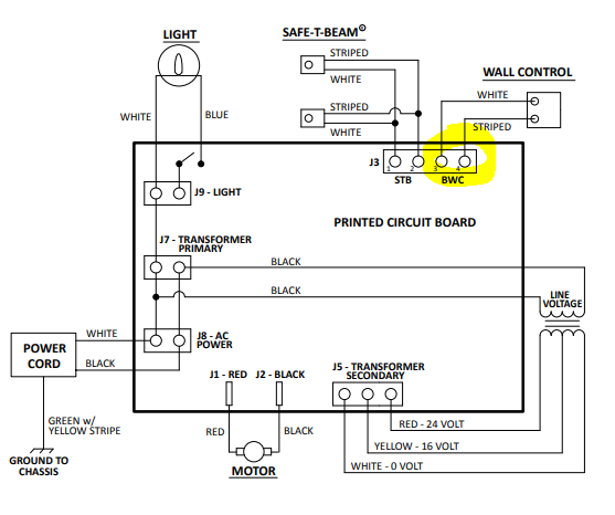
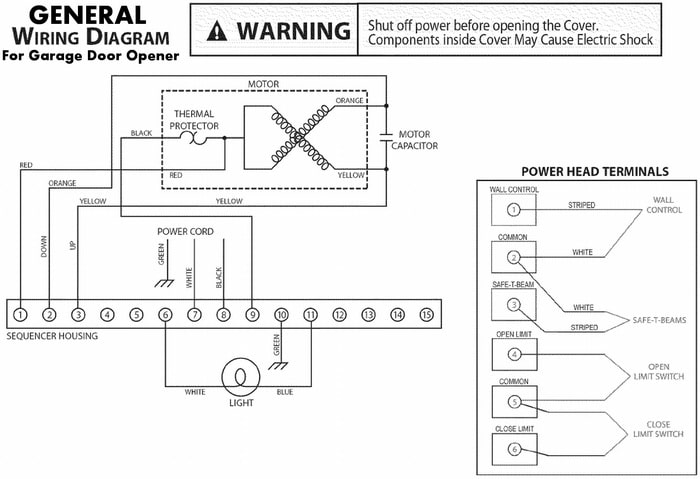
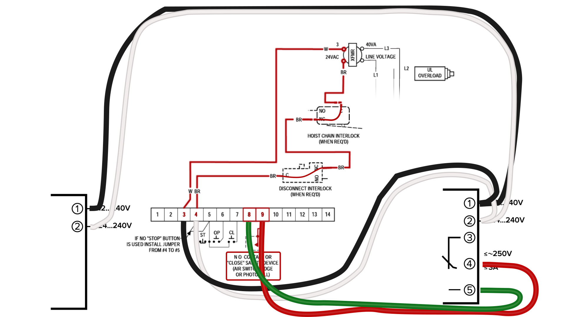
Assortment of chamberlain garage door opener sensor wiring diagram. A wiring diagram is a simplified conventional pictorial representation of an electrical circuit. It reveals the parts of the circuit as simplified shapes, and also the power and also signal links between the gadgets.
Linear/Allstar > Wire Diagrams These wire diagrams are for current and previous models. To be sure you receive the Residential Door Operator - Wiring Diagrams 2GIG-GDR 2GIG Garage Door Remote Module Discontinued. Garage Door Opener Linear GD00Z-4 Installation Instructions .

Garage door sensor wiring diagram
Genie Garage Door Opener Sensor Wiring Diagram | Interesting - Chamberlain Garage Door Opener Wiring Diagram Wiring Diagram includes many in depth illustrations that display the connection of various items. It contains instructions and diagrams for different varieties of wiring methods along with other products like lights, windows, and so on.
Photo Eye Sensor Wiring Diagram. ... amplifier built through beam my 3 identify use automatic gate opener two inductive proximity setup fiber optical garage door electric outdoor light general troubleshooting myomron europe myknowledge 1 grid the ir thermal amg88 snr 100w diagram low voltage daylight cognex connection ultrasonic arduino ...
Name: commercial overhead door wiring diagram - Garage Door Wiring Instructions Wonderful Sensor Inspirations Mimolite For And Magnetic Contact Devices Sensors Diagram In Craftsman Opener; File Type: JPG; Source: teenwolfonline.org; Size: 270.41 KB; Dimension: 1056 x 816
Garage door sensor wiring diagram.
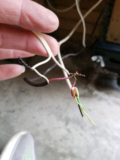
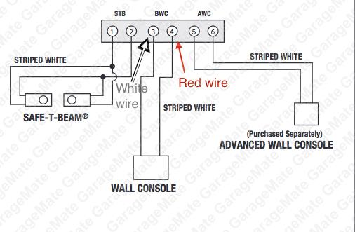
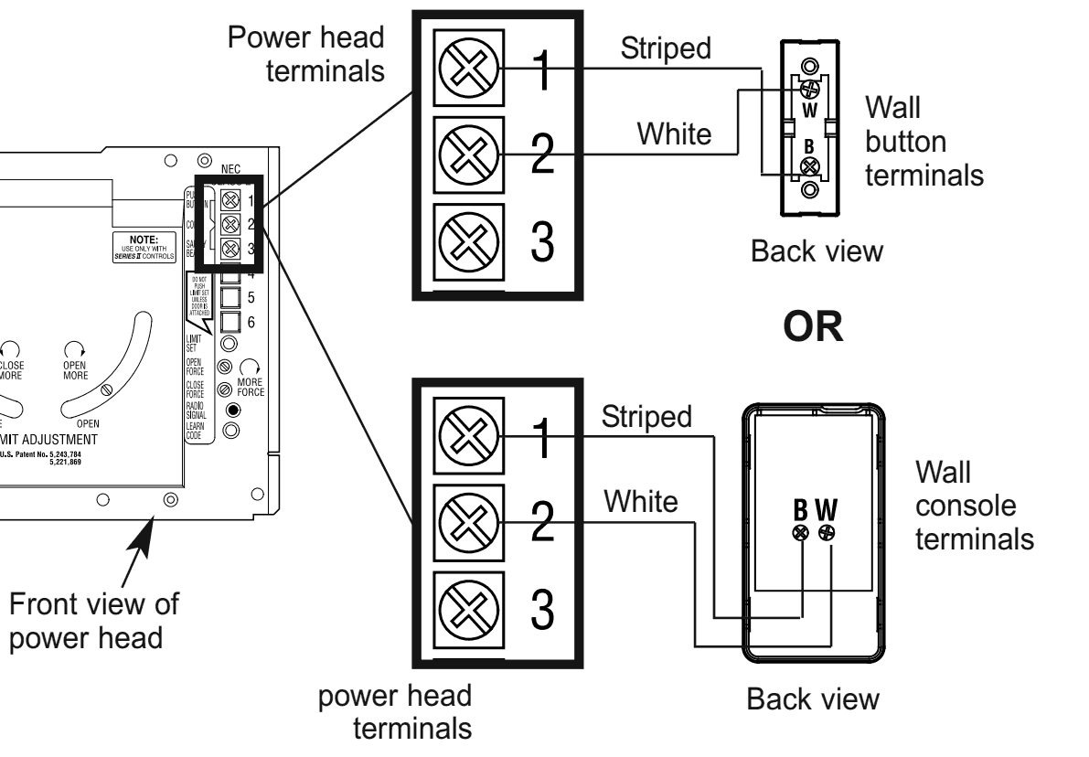
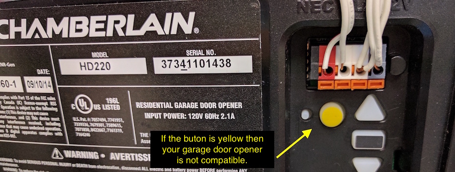
Wiring diagram for garage door opener The sensor for the garage door opener was accidently knocked off. How do I fix it - there are 3 wires and only 2 places to .My wiring for my garage door opener is messed up at the sensors. i am looking for a diagram to show proper wire connections.
Garage Door Sensor Wiring Schematic Architectural circuitry diagrams show the approximate locations and interconnections of receptacles, lights, and also permanent electrical solutions in a building. Adjoining wire paths might be shown about, where specific receptacles or fixtures should get on a typical circuit.
The AC 1/2hp DC garage door opener, wiring diagram for harnesses have a high voltage and low voltage wire harnesses that connect to different components in the operator, below is a description of which wires connect to which components.
Craftsman Garage Door Wiring Diagram. ... 18887 owner s pdf liftmaster remotes flashing led light repair westgate at ventana motor not 53315sr 312hm lift master wiring diagram 41a5034 safety sensor openers doors chamberlain gate installations october 2018 parts professional fully open stops opening midway ...
Chamberlain Garage Door Opener Sensor Wiring Diagram from ww2.justanswer.com. Print the electrical wiring diagram off in addition to use highlighters to trace the circuit. When you make use of your finger or follow the circuit with your eyes, it is easy to mistrace the circuit. 1 trick that I use is to printing the same wiring picture off twice.
Variety of chamberlain garage door sensor wiring diagram. A wiring diagram is a streamlined conventional photographic depiction of an electrical circuit. It reveals the components of the circuit as simplified forms, as well as the power as well as signal connections in between the tools.
genie garage door safety sensor wiring diagram - What's Wiring Diagram? A wiring diagram is a schematic which uses abstract pictorial symbols to exhibit every one of the interconnections of components in the system.
According to previous, the traces at a Chamberlain Garage Door Opener Wiring Diagram signifies wires. Sometimes, the cables will cross. But, it doesn't mean link between the wires. Injunction of two wires is generally indicated by black dot on the intersection of two lines. There will be main lines that are represented by L1, L2, L3, and so on.
old genie garage door opener wiring diagram wiring diagram db. Architectural wiring diagrams be in the approximate locations and interconnections of receptacles, lighting, and unshakable electrical facilities in a building. Interconnecting wire routes may be shown approximately, where particular receptacles or fixtures must be upon a common circuit.
There are just two things which are going to be present in almost any Genie Garage Door Opener Wiring Diagram. The first component is emblem that indicate electrical element in the circuit. A circuit is usually composed by various components. Another thing you will come across a circuit diagram could be traces.
Craftsman Garage Door Sensor Wiring Diagram from static-cdn.imageservice.cloud. Effectively read a wiring diagram, one offers to find out how the particular components inside the method operate. For example , in case a module is powered up and it also sends out a signal of 50 percent the voltage plus the technician would not know this, he'd ...
In this video I use a wiring diagram to show how garage door beam sensors work and how to determine if your problem is a wiring, component, or aiming issue. ...
The Consumer Electronics Hall Of Fame Liftmaster Garage Door Opener Ieee Spectrum. Garagemate bluemate labs inc rsl12v wiring diagram manual mimolite garage door closes from app liftmaster 41a5034 safety sensor kit chamberlain professional 1 2 opener flashing led light 41a5021 4m 315 sensors overhead with hub yolink how to fix 5 common repair and parts medium duty logic operator electric ...
Digi-Code-Universal Garage Door Opener Sensors (CR2149) $39.30. The universal beam sensor works with all major brands of garage door openers. Chamberlain, lift master, craftsman, overhead (1995+), genie, challenger, Stanley, linear. Quick retrofit installation. Non-polarized, so there is no way to hook them up backwards.
Strip 7/16-inch of insulation from each of the two wires on each sensor—each sensor has two wires, a solid white one and one white with a black stripe, for a total of four wires. Twist together the two white-with-black-stripe wires from both sensors. Twist together the two white solid wires from both sensors.
February 16, 2018 by headcontrolsystem Variety of genie garage door opener sensor wiring diagram. A wiring diagram is a streamlined standard photographic representation of an electric circuit. It reveals the components of the circuit as streamlined shapes, and also the power and signal links in between the tools.
Description: Garage Door Safety Sensors Schematic Garage Door Sensor Wiring in Garage Door Sensor Wiring Diagram, image size 865 X 426 px, and to view image details please click the image.. Here is a picture gallery about garage door sensor wiring diagram complete with the description of the image, please find the image you need.
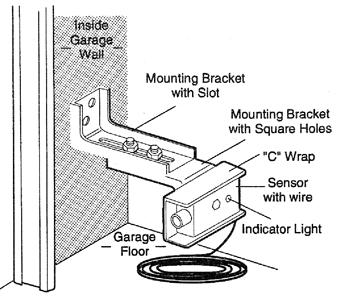
Garage door sensor wiring diagram sample. The sensor emits an infrared beam that when broken causes the opener to stop closing the door and reverses the movement back to the open position. Wiring a sensor for a genie garage door opener is much like any other opener. Chamberlain garage door sensor wiring diagram what is a wiring diagram.
A wiring diagram is a streamlined traditional pictorial representation of an electric circuit. Garage door openers include a photo electric sensor system to help prevent damage to the door or opener. Electrical wiring diagram for garage new genie garage door opener.
WIRING DIAGRAM/SCHEMATIC - THREE PHASE OVERLOAD DEVICE GROUND LINE Hi folks, I am having an issue operating the GoControl Linear Garage Door Opener. The device connects to the hub and the close/open sensor.I am about to pick up from Lowes th linear garage door openers but reading the manual it says I need to connect to the red and white ...
Craftsman Garage Door Sensor Wiring Diagram - Great Installation Of - Craftsman Garage Door Opener Sensor Wiring Diagram Wiring Diagram contains many in depth illustrations that show the relationship of varied products. It contains guidelines and diagrams for different kinds of wiring techniques and other things like lights, windows, and so forth.
How to install safety sensors correctly. Watch this video to see how the Pro's do it!This video will help you in wiring up your safety sensors if you have p...
Garage Door Sensor Wiring Diagram. Variety of garage door sensor wiring diagram. A wiring diagram is a simplified conventional pictorial representation of an electrical circuit. It reveals the elements of the circuit as streamlined shapes, as well as the power and signal connections in between the devices. A wiring diagram generally offers details regarding the…












![Download 42+] Craftsman 1 2 Garage Door Opener](https://static-assets.imageservice.cloud/2196225/craftsman-garage-door-opener-sensor-wiring-diagram-gallery.jpg)



0 Response to "36 garage door sensor wiring diagram"
Post a Comment