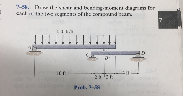
34 draw the shear diagram for 0 ≤ x ≤ 14 ft of the compound beam.
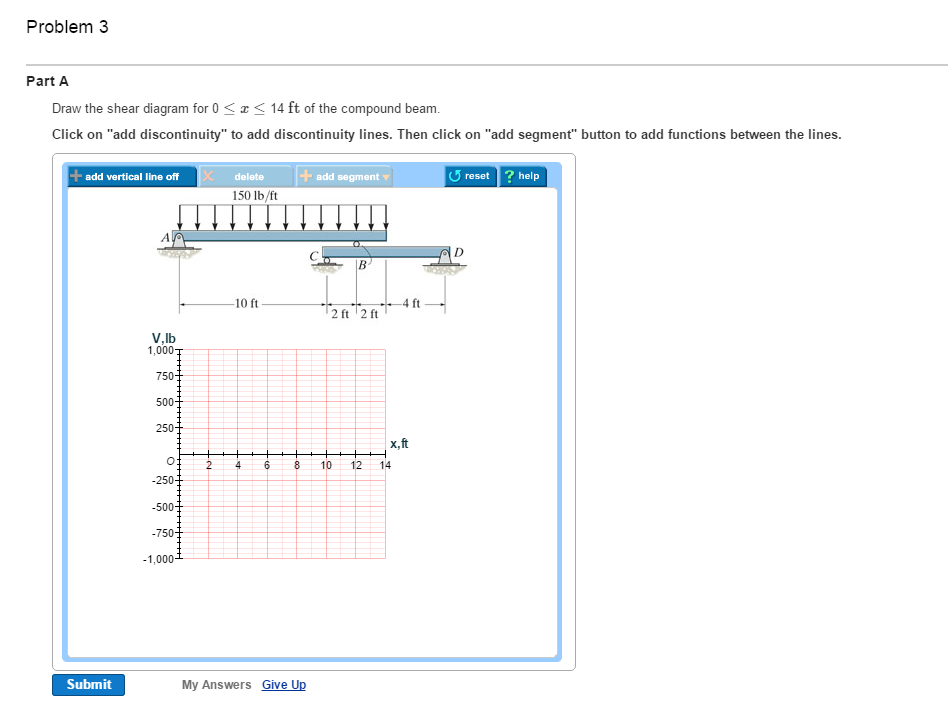
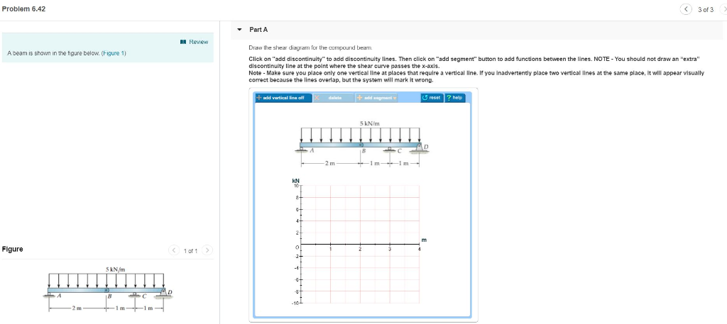
... 5 of 6> PartA Draw the shear diagram for 0 14 ft of the compound beam. ... 150 lb/ft U reset ? help 10 ft 4 ft V.lb 1,000 x,ft 2 4 6 8 10 12 14 -500 ... x + y - 3 = 0 x + 4 - 3 = 0 x = -1 So, the orthocenter is (-1, 4) The orthocenter lies on the vertex. Question 13. A woodworker is culling the largest wheel possible from a triangular scrap of wood. The wheel just touches each side of the triangle, as shown. Answer: a. Which point of concurrency is the center of the circle? What type
Mechanical engineering archive containing a full list of mechanical engineering questions and answers from May 17 2021.
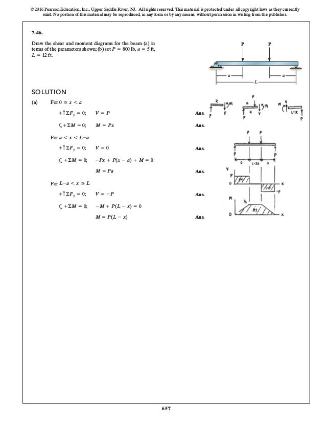
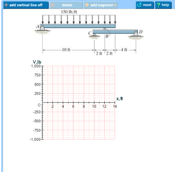
Draw the shear diagram for 0 ≤ x ≤ 14 ft of the compound beam.
Transcribed image text: Draw the shear diagram for 0 x < 14 ft of the compound beam Click on "add discontinuity" to add discontinuity lines. Mohr's circle is a two-dimensional graphical representation of the transformation law for the Cauchy stress tensor.. Mohr's circle is often used in calculations relating to mechanical engineering for materials' strength, geotechnical engineering for strength of soils, and structural engineering for strength of built structures. It is also used for calculating stresses in many planes by ... Transcribed image text: Problem 7.58 ? Part A Draw the shear diagram for 0 < x < 14 ft of the compound beam Click on "add discontinuity" to add ...
Draw the shear diagram for 0 ≤ x ≤ 14 ft of the compound beam.. A 0.599 g (1.29 mmol) portion of Bi 2 O 3, 0.527 g (3.3 mmol) of TeO 2, and 0.15 mL of HF solution were loaded in a 23 mL Teflon-lined autoclave. After tightly sealing, the autoclave was heated to 230 °C for 72 h and cooled to room temperature at a rate of 6 °C h-1. The product was filtered and washed with distilled water. Part A Draw the shear diagram for 0 <14 ft of the compound beam. L 150 lb/ft A B 10 ft 4 ft 2 ft 2 ft V. V,lb 1000 750 500 250 x, ft 12 14 10 8 6 2. W i and W x = effective seismic weights at levels i and x. ℎ i and ℎ x = heights from the base of the structure to floors at levels i and x. = summation of the product W i and over the entire structure. k = distribution exponent related to the fundamental natural period of the structure. For T ≤ 0.5s, k = 1.0, and for T ≥ 2.5s, k = 2.0. The size of the bitumen beam sample was: length, 127 ± 2 mm; thickness, 6.35 ± 0.05 mm; width, 12.7 ± 0.5 mm. The distance between the support pins was 100 mm. The deflection at this point was measured at 60 s, and the load was 980 ± 50 mN.
Peculiarities of Phase Formation in Mn-Based Na SuperIonic Conductor (NaSICon) Systems: The Case of Na 1+2x Mn x Ti 2-x (PO 4) 3 (0.0 ≤ x ≤ 1.5) Gustautas Snarskis Center for Physical Sciences and Technology (FTMC), Saulėtekio al. 3, LT-10257 Vilnius, Lithuania Programmable quantum simulators based on Rydberg atom arrays have recently emerged as versatile platforms for exploring exotic ... A simply supported beam AB carries a uniformly distributed load of 2 kips/ft over its length and a concentrated load of 10 kips in the middle of its span, as shown in Figure 7.3a.Using the method of double integration, determine the slope at support A and the deflection at a midpoint C of the beam.. Fig. 7.3. Simply supported beam. Solution. Support reactions. Mass loss − 0.313 ≤ 0.8 T0609-2011 Penetration (25 C) 64.3 ≥ 61 T0604-2011 The SBR powder was SBR 1502 produced by Tianjin Mingji Jintai Rubber and Plastic This work details the general structure of the clays used as a reinforcement phase in polymer nanocomposites. Clays are formed by the molecular arrangement of atomic planes described through diagrams to improve their visualization. The molecular knowledge of clays can facilitate the selection of the polymer matrix and achieve a suitable process to obtain clay-based polymer nanocomposite systems.
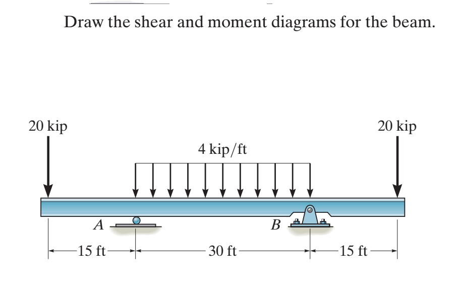
For the PEEK/CF (0°/0°) composite, its value was 422.8 ± 12.5 MPa at a strain of 0.017, while the peak stress was 190.2 ± 18.7 MPa at a strain of 0.020 for the PI/CF (0°/0°) one. Overcoming the maximum stress point resulted in the development of the fracture process, which corresponded to stage (III) of the analyzed diagrams. Draw the shear and moment diagrams for the beam. 12 kn 8 kn m 2 m problem 4 (25 pts): if the cross section of the beam in problem 3 is rectangular with width b = 0.2m and height h = 0.4m. what is the maximum bending stress on the beam and where it is located on the beam (axial position) and its cross section (distance to the neutral axis)?. 64 ft × 104 ft in plan. Eave height of 30 ft. Apex height at elev. 36 ftRoof slope 3:16 (10.62°) With opening. Cladding. Purlins spaced at 2ft. Wall studs spaced at 2ft. In our ASCE 7-10 wind load example, design wind pressures for a large, three-story plant structure will be determined. Fig. 1 shows the dimensions and framing of the building. Draw the bending-moment diagram for member CBD (0 ≤ x ≤ 8 ft) of the compound beam. 14 ft of the compound beam. Show transcribed image text. Expert Answer.
Capacity 5-1/2 in. 270 14,120 11. I Beam Load Capacity Chart. • Values shown are in full compliance with the current RMI Specifications. 46 in w (load per foot) = 1200 lb per ft l (beam span) = 14 ft Where E is a constant for steel = 30,000,000 psi And I is the moment of inertia Solving for.
Temperature distribution during laser heating (t = 39 s, region 0 ≤ x ≤ 50, deformation scale factor 10). Temperature profiles along the axis of the beam are shown in Figure 9 . Locations of the top temperature values for time instants t = 1 s, 10 s, 20 s and 40 s correspond to the current locations of the laser spot, while the profile for ...
Question: Draw the shear diagram for 0 ? x ? 14 ft of the compound beam. This problem has been solved! See the answer ...

For a simply supported beam of length L, the bending moment M is described as M = a (x - x 3 /L 2), 0 ≤ x < L; where a is a constant. The shear force will be zero at The shear force will be zero at 1. x = L/2
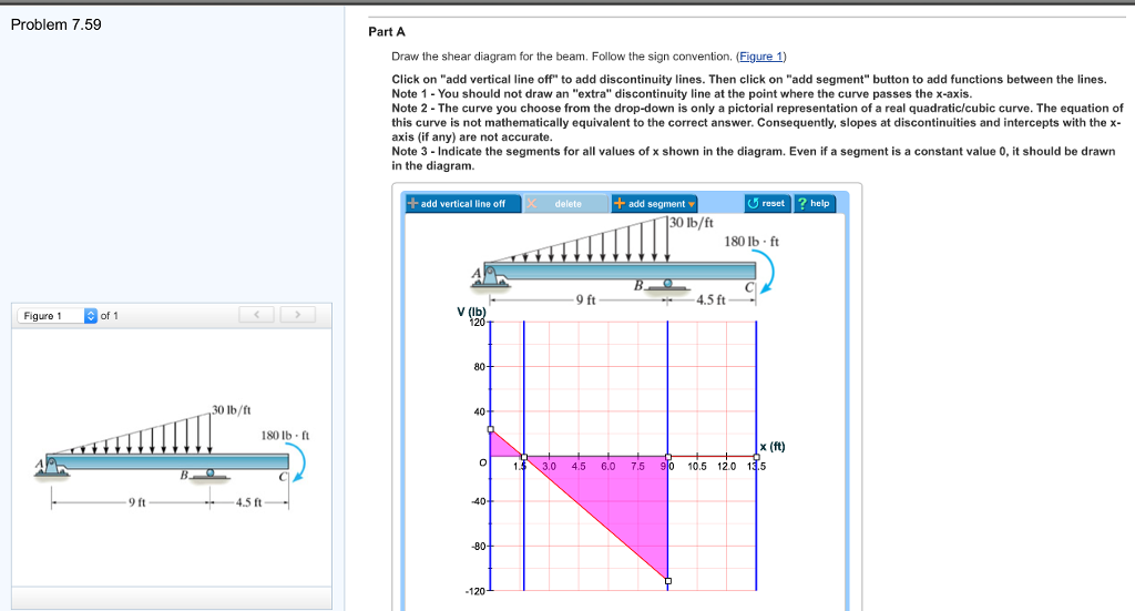
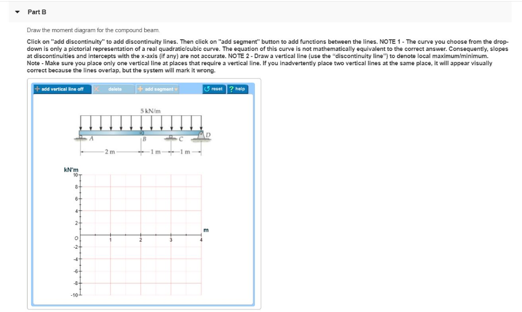
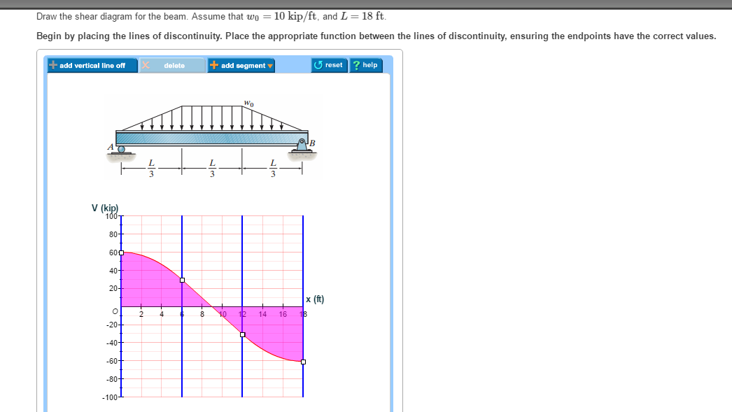
Draw the shear diagram for the beam. assume that m0=200lb⋅ft, and l=20ft.. Draw the shear diagram for the beam. Assume that M0=200lb⋅ft, and L=20ft. Begin by placing the lines of discontinuity. Place the appropriate function between the lines of discontinuity, ensuring the endpoints have the correct values. Note - Make sure you place only ...
notches is a = 6 mm, corresponding to a lling fraction F A = 0.144; (b) beam B, with b = 20.83 mm and lling fraction F B = 0.499. (c) (c) B e a mC ,w h e r et h e r s th a l fi si d e n t i c a lt ...
Distance from point A to point H on x-axis (l AH x) 0.4933 m: Area of flexible beam 1 (s 3) 3.334 × 10 − 3 m 2: Distance from point A to point H on y-axis (l AH y) 0.2281 m: Area of flexible beam 1 (s 4) 2.009 × 10 − 3 m 2: Distance from point B to point H on x-axis (l BH x) 0.21 m: Area of rodless chambers (s A) 3.117 × 10 − 3 m 2
Surface Area of a Sphere. A sphere is a perfectly round geometrical 3-dimensional object. It can be characterized as the set of all points located distance. r. r r (radius) away from a given point (center). It is perfectly symmetrical, and has no edges or vertices. A sphere with radius.

Assemble Test Cover (See Tools at back of manual for drawing) to Brake Housing (6) using four Bolts (15) evenly tightening Bolts (15) to 80-100 ft-lbs. 10. Check the brake for release.
Concrete T Beam Design to Eurocode 2 - Strain Compatibility Method. Design concepts 3. 94 (7) Only 2 left in stock - order soon. Strut-and-tie modeling is currently recommended in most U. 0 NOTATION acj ex. Title: Lecture 17 Design of Reinforced Concrete Beams for Shear 1 Lecture 17 - Design of Reinforced Concrete Beams for Shear.
Transcribed image text: Draw the shear diagram for 0 lessthanorequalto x lessthanorequalto 14 ft of the compound beam. Click on "add discontinuity" to add ...
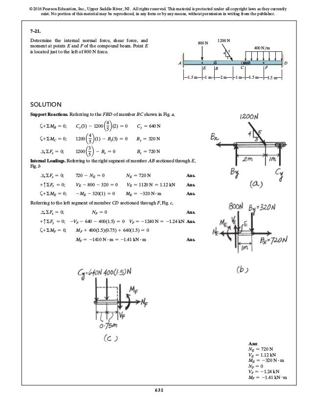
4 ft. A. The free-body diagram of the beam's right segment sectioned through ... x = 0. 06 Solutions 46060_Part1 5/27/10 3:51 PM Page 330 ... compound beam.143 pages
A particle in an infinite square potential well wouldn't be a harmonic oscillator, you're confusing two entirely different models, so I'm not sure quite what you're asking, and certianly the number of dimensions is irrelevant, if you're asking why is the Schrondinger Equation sinusoidal then the answer is simple, the linear, or in your case ...

In order to solve the problems of the smooth surface of basalt fiber and its weak interfacial adhesion with emulsified asphalt cold recycled mixture, a silane coupling agent (KH550) was used to treat the surface of basalt fiber and the effects of treatment concentration and soaking time on fiber modification were studied. The influence of silane coupling-modified basalt fiber (MBF) on the ...

Service and Maintenance Manual Models EC600SJ, H600SJ, EC600SJP, H600SJP PVC 2001 31215028. Sepetember 12, 2019 - Rev A. AS/NZS
With CBeam, a composite beam section can be created and edited graphically using any combination of rectangle, triangle or I-beam shapes. If non-composite, the loads are resisted by the steel beam alone. In this case the section modulus and moment of inertia are b (4h) 2 /6 and b (4h) 3 /12, respectively.

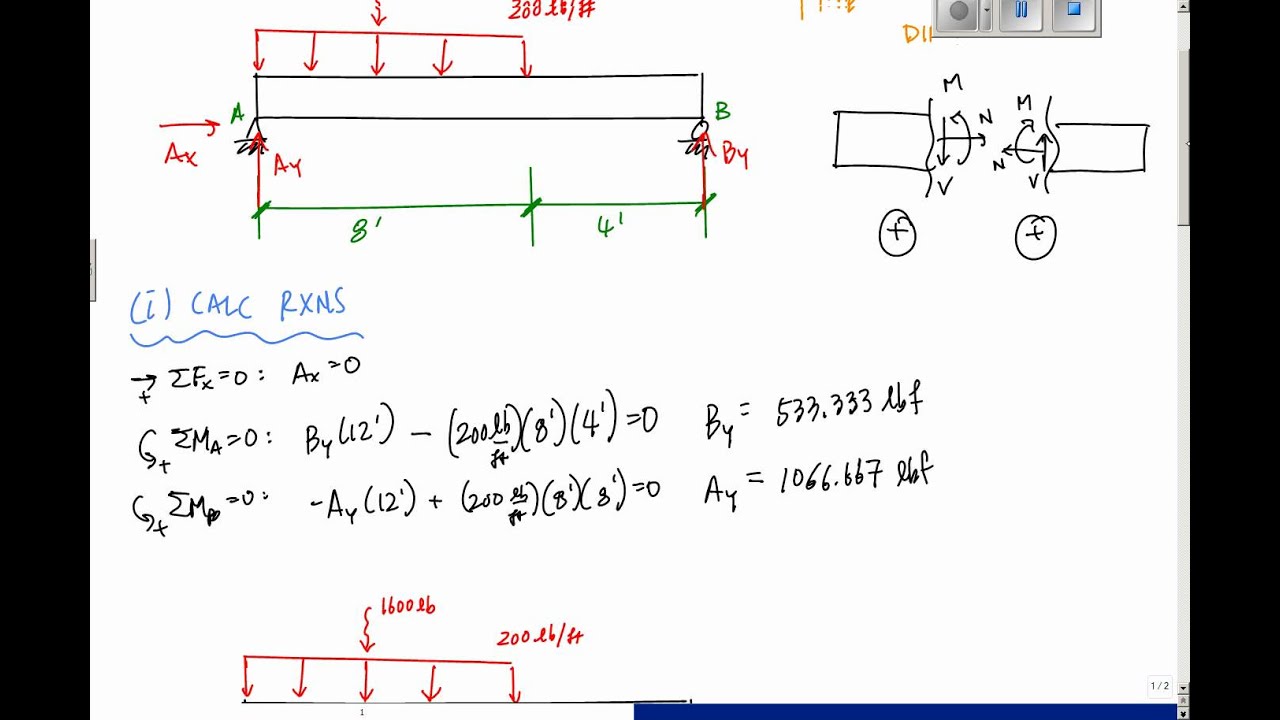
Once you have the reactions, draw your Free Body Diagram and Shear Force Diagram underneath the beam. Finally calculating the moments can be done in the following steps: 2. From left to right, make "cuts" before and after each reaction/load. To calculate the bending moment of a beam, we must work in the same way we did for the Shear Force ...
CRN: 29476 / 534711School of Science, Engineering & EnvironmentTRIMESTER TWO EXAMINATIONPROGRAMMES:BEng (Hons) Civil EngineeringBEng (Hons) Civil & Architectural EngineeringMEng (Hons) Civil EngineeringMEng (Hons) Civil &…
Atomic layer deposition (ALD) is the fastest growing thin-film technology in microelectronics, but it is also recognized as a promising fabrication strategy for various alkali-metal-based thin films in emerging energy technologies, the spearhead application being the Li-ion battery. Since the pioneering work in 2009 for Li-containing thin films, the field has been rapidly growing and also ...
Draw the bending-moment diagram for member CBD (0 ≤ x ≤ 8 ft) of the compound beam. 150 lb/ft 10 ft 2 ft 72103-4ft -. Show transcribed image text. Expert ...
Transcribed image text: Problem 7.58 ? Part A Draw the shear diagram for 0 < x < 14 ft of the compound beam Click on "add discontinuity" to add ...
Mohr's circle is a two-dimensional graphical representation of the transformation law for the Cauchy stress tensor.. Mohr's circle is often used in calculations relating to mechanical engineering for materials' strength, geotechnical engineering for strength of soils, and structural engineering for strength of built structures. It is also used for calculating stresses in many planes by ...
Transcribed image text: Draw the shear diagram for 0 x < 14 ft of the compound beam Click on "add discontinuity" to add discontinuity lines.

0 Response to "34 draw the shear diagram for 0 ≤ x ≤ 14 ft of the compound beam."
Post a Comment