39 commercial defrost timer wiring diagram
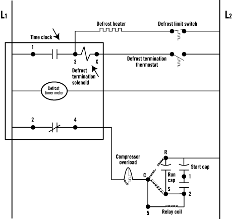
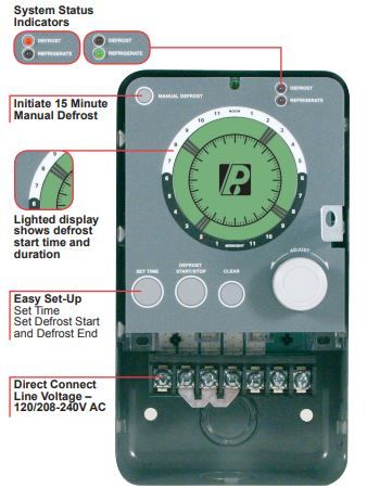
Whirlpool Refrigerator Defrost Timer Wiring Diagram. Double Pole Wall Thermostat Wiring Diagram. Cadet Double Pole Thermostat Wiring Diagram. Magnetic Door Lock Wiring Diagram. Old Genie Garage Door Opener Wiring Diagram. Genie Garage Door Opener Sensor Wiring Diagram. Liftmaster Commercial Garage Door Opener Wiring Diagram. Wires NWhite Neutral XPurple defrost termination This info obtained from sheet included with the Grasslin. 4tors Paragon Commercial Defrost For Electric Heat Hot Gas or Compressor Shutdown Defrosting Bracket and 50 Hz available Applications and Wiring Diagrams MECHANICAL DEFROST TIMER Series.
Wiring Diagram. Freezer defrost timer wiring diagram true t 23f manualzz 318 icm system commercial refrigeration temperature refrigerator paragon 632 20 whirlpool installation instructions for 38byc 018 060 60 hertz diagrams york electrolux ew23cs75qs english demand controls time hvac r basics systems national smartvapii heatcraft products pro3 service manual koldpia hobart dishwasher full ...

Commercial defrost timer wiring diagram
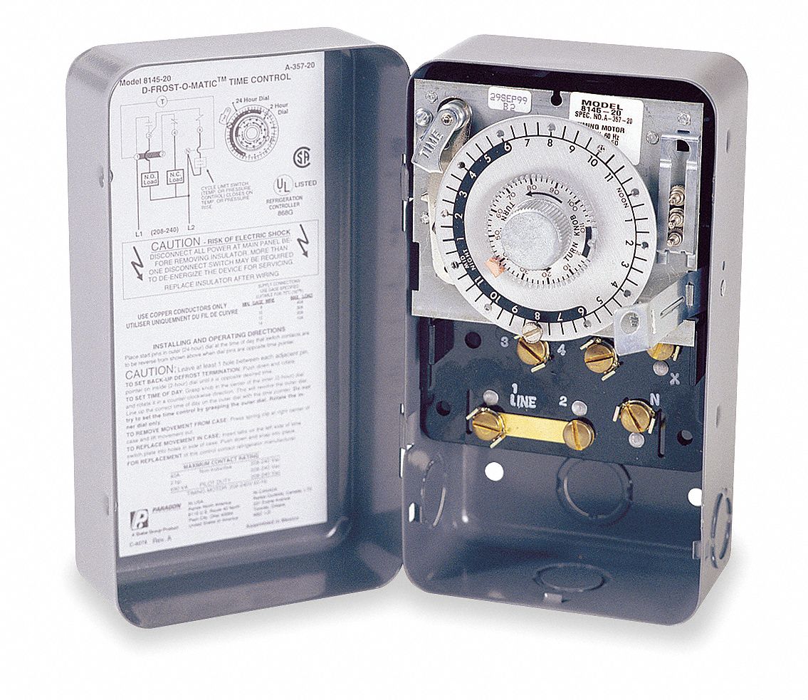
Paragon defrost timer wiring diagram paragon defrost timer wiring regarding 8145 20 wiring diagram image size 577 x 600 px and to view image details please click the image. Here is a picture gallery about 8145 20 wiring diagram complete with the description of the image please find the image you need. Master Bilt Qsf7768 C 6 X 8 X 7 7 Indoor Self Contained Walk In Freezer Ebay In 2021 Walk In Freezer Commercial Kitchen Equipment Walk In Freezer Home . ... Collection Of Freezer Defrost Timer Wiring Diagram Wiring Diagram At For Walk In Freezer Timer Diagram . 2007 honda pilot engine diagram wiring diagrams. Architectural wiring diagrams act out the approximate locations and interconnections of receptacles, lighting, and steadfast electrical services in a building. Interconnecting wire routes may be shown approximately, where particular receptacles or fixtures must be upon a common circuit.
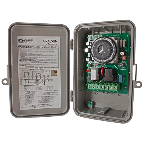
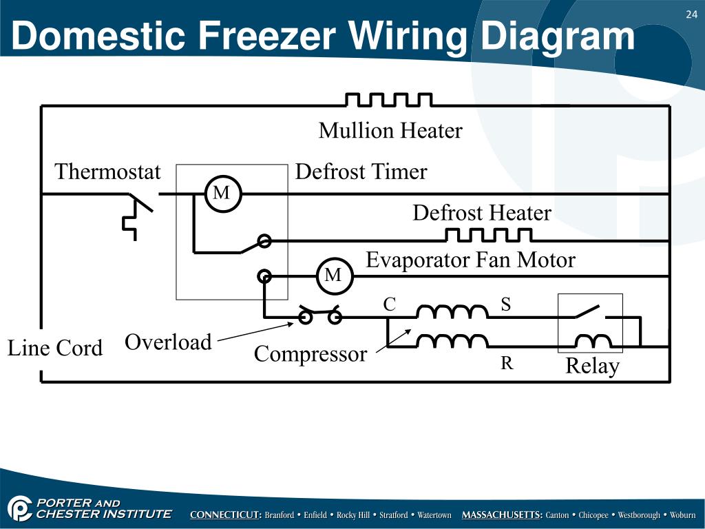
Commercial defrost timer wiring diagram. Collection Of Freezer Defrost Timer Wiring Diagram Wiring Diagram At For Walk In Freezer Diagram Freezer . Pin By Subhendu Mohanty On Misc Civil Arch Construction Hvac Design Hvac Duct Plumbing Drawing . ... 50 Cold Storage Plant Layout Wh6m Refrigeration And Air Conditioning Electrical Engineering Projects Commercial Hvac . Commercial refrigeration wiring diagrams. Walk in freezer wiring diagram. Retail store walk in coolers and freezers boiler operating control used as a thermostat universal defrost timer wiring. Wiring diagram a schematic drawing of the wiring of an electrical system. Commercial Circuit Simulator Goes Free Hackaday Quite Universal Circuit Simulator Sourceforge Net Top Ten Online Circuit Simulators Electronics Lab Rik 10 Online Circuit Simulators For Dealing With Electronics Projects ... Grasslin Controls 40a Defrost Timer Wiring Diagram. Defrost Timer Controls. Typical line voltage wiring diagram. Determine location of. All electrical parts and wiring must be shielded from torch flame. DO NOT allow torch to touch. Refrigerator Temperature. In this video you can learn about the defrost timer wiring diagram of a frost free refrigerator and circuit.
Commercial Defrost Timer Wiring Diagram from schematron.org Effectively read a cabling diagram, one has to know how typically the components inside the method operate. For instance , if a module is powered up and it sends out the signal of fifty percent the voltage in addition to the technician would not know this, he'd think he provides an ... Garbage Disposal Wiring Diagram from static-resources.imageservice.cloud Effectively read a cabling diagram, one offers to find out how typically the components within the system operate. For instance , if a module will be powered up and it also sends out a signal of half the voltage in addition to the technician does not know this, he'd think ... ⭐⭐⭐⭐⭐ On Off Timer Circuit Diagram; Views: 17692: Published: 3.3.2021: Author: rifugi.liguria.it: Circuit Diagram Timer On Off . About Diagram Timer Circuit On Off ... Fastest No Frost Refrigerator Wiring Diagram. Diagram paragon 8145 20 wiring timer diagrams defrost bhzer precision multiple controls official older frigidaire fixed frt045gm question system whirlpool refrigerator time hvac r installation instructions for walk in freezer w10822278 china sankyo robertshaw products a769 00 ge schematics 30 bypass basic universal timers 9145 9045 magic chef no ...
Electrical wiring diagram house, and of course what we provide is the most best of images for walk in freezer defrost timer wiring diagram on. Paragon defrost timer 8145 20 wiring diagram with grasslin inside awesome collection of in 11, walk in freezer wiring diagram fresh defrost timer concer biz unbelievable for of paragon 10, maxresdefault ... Collection of paragon defrost timer 8145 20 wiring diagram. The defrost timer acts as a clock, that switches the refrigerator from the freezing cycle to the defrost cycle and back. EC series programming manual shows wiring, explains keypad, has steps for setting current time, and shows 24 steps for programming timer. DC could flow not just ... Walk In Freezer Wiring Diagram - wiring diagram is a simplified suitable pictorial representation of an electrical circuit.It shows the components of the circuit as simplified shapes, and the facility and signal links between the devices. Description: Freezer Defrost Timer Wiring 220V Commercial Freezer Defrost Timer with Walk In Freezer Defrost Timer Wiring Diagram, image size 598 X 452 px ... A wiring diagram is a simplified traditional pictorial representation of an electric circuit. It shows the elements of the circuit as simplified shapes as well as the power and signal links in between the gadgets. Commercial Refrigeration Temperature And Defrost Controls.
Commercial defrost timers diagrams here you are at our site, this is images about commercial defrost timers diagrams posted by Alice Ferreira in Commercial category on . Same thing still happening, the temp on the coil will get down to below 0 and ice up, i think the switch will close at 15deg. The defrost timer is most likely on the control board.
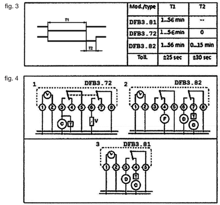
Paragon 8145 20 defrost timer wiring diagram. It reveals the elements of the circuit as simplified forms and also the power and also signal connections between the tools. Collection of paragon defrost timer 8145 20 wiring diagram. 8047 20 208 240 for electric heat defrosting auxiliary contact models 50 hz available open open closed 4 110 min.
2007 honda pilot engine diagram wiring diagrams. Architectural wiring diagrams act out the approximate locations and interconnections of receptacles, lighting, and steadfast electrical services in a building. Interconnecting wire routes may be shown approximately, where particular receptacles or fixtures must be upon a common circuit.
Master Bilt Qsf7768 C 6 X 8 X 7 7 Indoor Self Contained Walk In Freezer Ebay In 2021 Walk In Freezer Commercial Kitchen Equipment Walk In Freezer Home . ... Collection Of Freezer Defrost Timer Wiring Diagram Wiring Diagram At For Walk In Freezer Timer Diagram .
Paragon defrost timer wiring diagram paragon defrost timer wiring regarding 8145 20 wiring diagram image size 577 x 600 px and to view image details please click the image. Here is a picture gallery about 8145 20 wiring diagram complete with the description of the image please find the image you need.
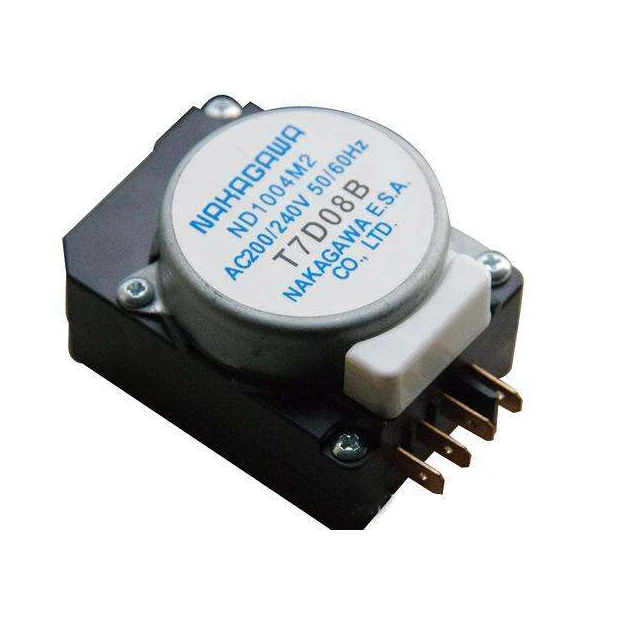
Good Quality R 8014 Nt0804m2tp Nakagawa Defrost Timer View Defrost Timer Nakagawa Product Details From Guangzhou Zhigao Freeze Equipment Co Ltd On Alibaba Com

No Frost Refrigerator D Frosting Timer Function And Connection Fully4world Refrigeration And Air Conditioning Timer Hvac Air Conditioning











0 Response to "39 commercial defrost timer wiring diagram"
Post a Comment