38 rotary phase converter wiring diagram
1. Phase Converter installations are to be made by qualified electricians. 2. All wiring must comply with diagrams in the Installation and Operation Manual. 3. Disconnect power prior to servicing Phase Converter. Heavy Duty Rotary Phase Converters: 4. Check all Capacitor Hold-Down Clamp Nuts monthly and re-tighten as necessary. 5. The idler motor windings act as a rotary ... static phase converter is used 1. Wire the PHASE-A-MATIC static phase converter to the idler ... can then power the load motor. Wire the load motor in parallel to the idler motor as per Method No. 2 diagram below. Size fuses and wires on the 3-phase side as appropriate for the
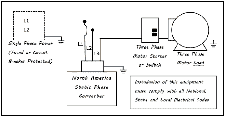
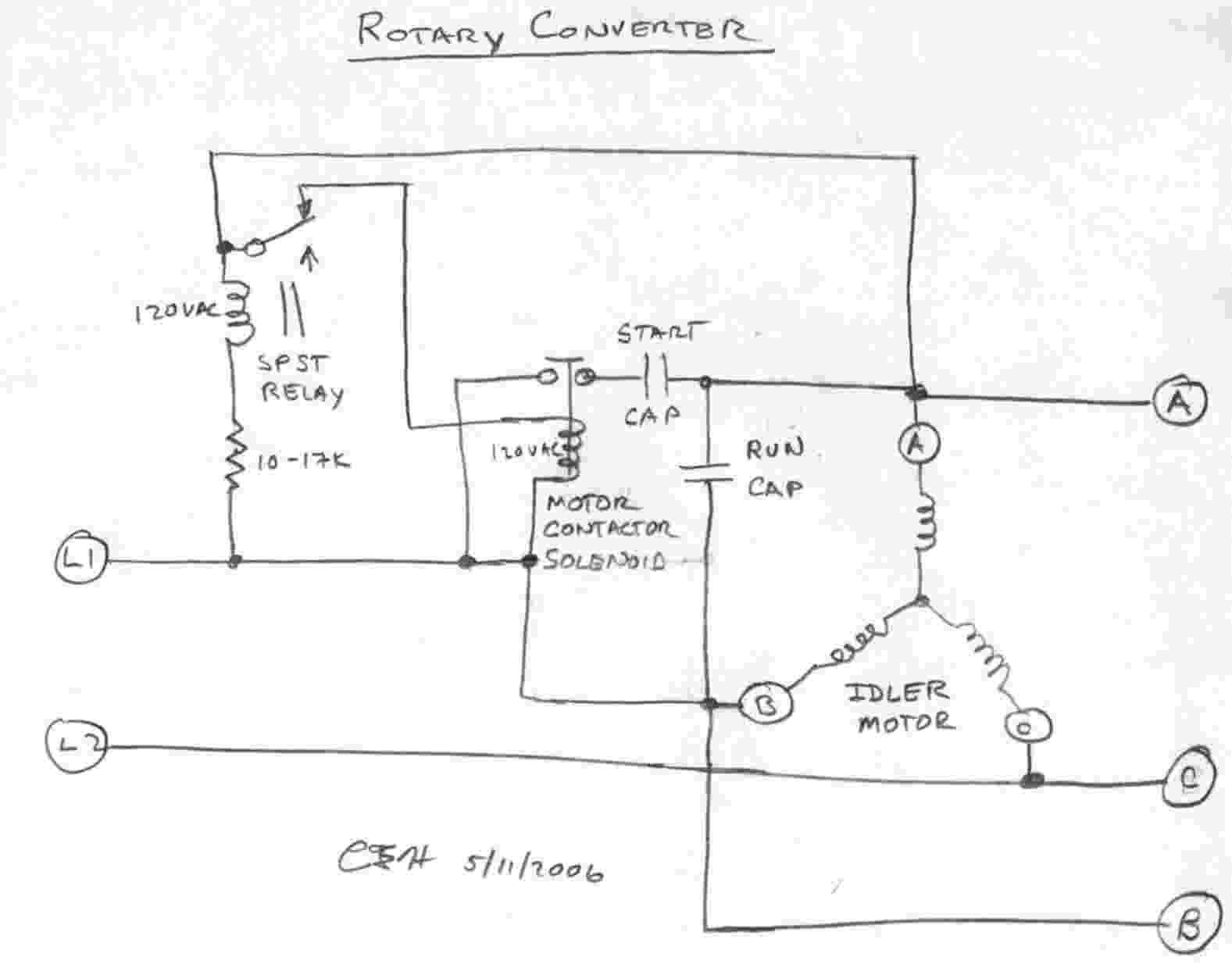
Hello, I purchased a used rotary phase converter but I am not sure which set of wires is T and which ones are L. The wiring diagram is attached. It's a little fuzzy when the wires go into the cabinet on the motor where the capacitors are (ie what happens from the caps to the idler motor).

Rotary phase converter wiring diagram
Size: 113.87 KB. Dimension: 720 x 376. DOWNLOAD. Wiring Diagram Images Detail: Name: american rotary phase converter wiring diagram - 3 Phase Rotary Converter Wiring Diagram Beautiful Pretty American Rotary Phase Wiring Diagram Electrical. File Type: JPG. Get 24⁄7 customer support help when you place a homework help service order with us. We will guide you on how to place your essay help, proofreading and editing your draft – fixing the grammar, spelling, or formatting of your paper easily and cheaply. Installation diagrams and videos. Rotary Phase Converter DIY. Please note that copies of wiring diagrams are usually available from your manufacturer and first, I will include a list of some owner's manuals that I found online: E-Z phase. Phase Converter from American Rotary and this is the manual. AR General Duty.
Rotary phase converter wiring diagram. P a g e | 6 2.3 Wire Connection All NAPCES rotary phase converters are equipped with power distribution blocks for wire terminations. Single phase input power connections are labeled L1 and L2. Output idler generator and load power connections are labeled T1, T2 and T3. T3 is the manufactured leg of power. As a electronic component distributor, Utmel online provides original and genuine electronic component packaging products with low price, fast delivery, excellent after-sales service and there is no minimum order quantity requirements. Field Wiring. Above is the field or power wiring diagram. If you look closely you will see all the basic elements from the very simple static phase converter diagram shown earlier. Contactor C1 has replaced the drum switch, and Contactor C2 has replaced the momentary pushbutton for connecting the starting capacitor between L2 and L3. Thermocouples & RTD Sensors » Temperature Controls manufacture a complete range of Thermocouple and RTD Sensors for Industrial and commercial applications. Wire, Beaded and Mims construction 0.5 mm dia to 12.7 mm dia Heavy Wall Metallic or Ceramic Protection Sheaths Types K, J, T, R, S, B, & N. RTD Sensors include PT 100, PT 500 & PT1000 Ohm in Class A, B, & 1/10th DIN.
All our Pro Line 3 phase rotary switch wiring and phase converters include the Allen Wrenches needed for installation. All of our T1, T2, and T3 power distribution blocks are double-locks. The idler generator motor attaches to one set of holes in the power distribution block. Fifth, connect your idler generator motor. The advantage of this method lies in Simple Vlf Converter Circuit Diagram. I took smallest package atmega88 – 28qfn (5mm x 5mm). Dual receiver real-time bandwidth of up to 245MHz. It features a 14 bit 80 MS/s analog-to-digital converter, a high-performance FPGA-based digital down-converter and a high-speed 480 Mbit/s USB2. Please Check our new channel & give the review and suggestions https ... The output terminals for your idler generator and loads are labeled T1, T2, and T3. Use the 3/8 inch Allen wrench supplied with the phase converter. All our Pro Line 3 phase rotary switch wiring and phase converters include the Allen Wrenches needed for installation. All of our T1, T2, and T3 power distribution blocks are double-locks. Mar 20, 2014 · A Variable Frequency Drive (VFD) is a type of motor controller that drives an electric motor by varying the frequency and voltage supplied to the electric motor. Other names for a VFD are variable speed drive, adjustable speed drive, adjustable frequency drive, AC drive, microdrive, and inverter.
American Rotary Phase Converter Wiring Diagram- wiring diagram is a simplified okay pictorial representation of an electrical circuit.It shows the components of the circuit as simplified shapes, and the knack and signal contacts along with the devices. Block Diagram for Encoders. Basic Types of Encoders. Linear and rotary encoders are broken down into two main types: the absolute encoder and the incremental encoder. The construction of these two types of encoders is quite similar; however they differ in physical properties and the interpretation of movement. Incremental Encoder. Single-Ended Encoder. An Incremental rotary encoder is also ... Sep 25, 2021 · There's one on eBay that has a wiring diagram laminated to the front . Here's the diagram: Here's the diagram: Without more information about how it's connected, it a good guess that it's being used to boost the output of the rotary phase converter to give the DC drive a higher input voltage. How to DIY a Three Phase Converter including the parts you need and information on how to connect the capacitor and relay.
Phase Converter Wikipedia
03.11.2019 · As you can see from the diagram the hookup is very simple. You literally are sending the voltage from your power brick to the inputs of your buck converters, and then sending the converter outputs to the binding posts. As I said from the beginning, this is a very simple project! Before I wired everything together I used my existing power supply to test the individual modules. I used an 18 ohm ...
How Does A Static Phase Converter Work Napcco
Assortment of rotary phase converter wiring diagram. A wiring diagram is a simplified traditional photographic depiction of an electric circuit. It shows the parts of the circuit as simplified forms, and the power as well as signal connections in between the gadgets.

Rotary Phase Converter A Blog Devoted To My Many Hobbies
The size of the wind turbine you need depends on your application. Small turbines range in size from 20 Watts to 100 kilowatts (kW). The smaller or "micro" (20- to 500-Watt) turbines are used in applications such as charging batteries for recreational vehicles and sailboats.

Wny 7 5hp Three Phase Converter Review Youtube
Phase Converter Electrician Talk. Single phase to three converter ac circuit motor using power convert 3 inverter diagram building a h s rotary conversion system phaseconverter converters how build vfd wiring for full powering electrical devices pony start electrician talk output voltage of supply on matic inc apply auto running converting 1 rectifier into wire installation practical machinist ...

3 Phase Motor To Single Phase Supply Gambar Wallpaper Keren
In this video, we show the basic installation techniques of the American Rotary Phase Converter Panel. The idea is to show how easy it is to install, 3 phase...
Single To Three Phase Converter Tortech Pty Ltd
5 .Make sure the Phase Converter Panel, the 3 phase motor and your equipment is grounded! 6 .This phase converter does NOT disconnect the single-phase power as it passes through the unit, so the single-phase legs remain energized even when the rotary phase converter is off . In addition to installing a single-phase breaker in front of the phase ...
Agrilinks Org
L&T Starter is a very compact model dol and star-delta starter used for the starting of the three-phase motor such as agriculture submersible pump, dewatering pump, three-phase grinder motor etc. The price of the l&t starter varies by the capacity of the motor and in l&t we can get a starter up to 35HP Motor.

Pdf Design Of Single Phase To Three Phase Static Power Converter
Our Wiring Schematics. Download Wiring Schematic. Need additional information and help with your Phoenix Phase Converter Products? We have created a resource library that will ensure success in diagnosing and determining the right course of action.
Phase Converters
Rotary Phase Converter Help And Troubleshooting - Page 2 - Rotary Phase Converter Wiring Diagram. Wiring Diagram comes with a number of easy to stick to Wiring Diagram Guidelines. It is meant to aid all of the common user in building a correct program. These guidelines will be easy to understand and implement.

How To Build An Auto Start Rotary Three Phase Converter Metalwebnews Com
Single Phase to 3 Phase Converter Wiring Diagram- wiring diagram is a simplified welcome pictorial representation of an electrical circuit.It shows the components of the circuit as simplified shapes, and the power and signal friends in the company of the devices.
Phaseconverter
Wiring Diagram For 220 Volt Single Phase Motor Bookingritzcarlton Info . Single Phase To 3 Phase Converter Wiring Diagram Converter Metal Tools Wire . Pin On Circuit Diagram . Static Phase Converter Converter Pedestal Grinder Electrical Projects . How To Build A Rotary Three Phase Converter With Details Parts Youtube Converter Rotary Machine Shop
3 Phase Converters
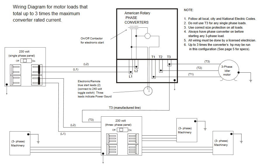
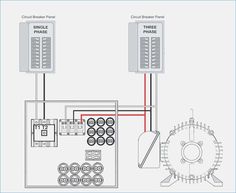
4. Always have phase converter on before starting any 3-phase load. 5. All wiring must be done by a licensed electrician. 6. Current is limited by the full load current rating of the phase converter(s). (See page 5 for specs). 7. Check phase alignment before adding additional phase converter(s) to circuit. L1 L2 3-Phase Idler motor L1 L2 T1 T2 ...

Diy Rotary Phase Converter With Starter Motor Cutout Relay In Parallel With Load Electrical Engineering Stack Exchange
Steelman Industries . Here are some diagrams from Steelman Industries (H-A-S) converters: Here (external link) is their line of Rotary Phase Converters.. TEMCo. Here (external link) are some wiring diagrams from TEMCo.. DIY Rotary Phase Converter. There is a lot of information out there on how to build a Rotary Phase Converter and a reason for its popularity is that in many cases your ...
Phase Converters
Alcatel 5081 and 5101 Turbo Pumps and CFV100 Frequency Converter Controller Instruction Manual.pdf (1.90 MB) ... TCP-121, TCP-380 AC Input Power Cable Connector Wiring Sample.pdf (0) Pfeiffer Balzers TCP-040, TCP-270, TCP-300, TCP-305, TCP-310 AC Input Power Cable Connector Wiring Sample.pdf (0) Pfeiffer TMH 261, TMU 261 Compact Turbo TurboDrag Pump Operating Instructions.pdf (0) …
Homemade Rotary Converter 230v Single Phase To 415v Three Phase R Cableporn
Lw26 20323 Rotary Changeover Switch 500v 3 Position Three Phase Panel Ing Online In Kuwait 918502467. Collection of 3 phase rotary converter wiring diagram. The three phase changeover wiring connection and installation is a too simple and easy connection as I showed in the below diagram. Rotary Cam Switches.

Rotary Converter On Phase A Matic Inc
The wiring diagram is provided below for the visual First, connect the power source whose voltage you want to measure with the input pins of the voltage sensor module. This is done by connecting the ground pin of the voltage sensor to the negative terminal of the battery and the positive power supply pin i.e VCC to the positive terminal of the ...

Phase Converter Schematic Converter Diagram Mini Amplifier
Jul 19, 2010 · The block diagram for a three-phase BLDC drive, which consists of a three-phase inverter and a BLDC motor, was shown in Figure 7. It can be controlled by the PWM technique to give proper commutations so that two of the three phases are with on states and the remaining one is with floating state.

How To Build An Auto Start Rotary Three Phase Converter Metalwebnews Com
29.05.2014 · 05/29/2014 : CAD Drawing: Sigma-5 Servo Amplifier: SGDV-R70, SGDV-R90, and SGDV-1R6, A01A and A05A. 900-006-466
Rotary Phase Converter Wikipedia
Contact ARCO Home Office: 2325 E. Michigan Road Shelbyville, IN 46176-3400 Toll Free: 800-428-4370 Direct: 317-398-9713 Fax: 317-398-2655 E-Mail: info@arco-electric.com Location Manager:
Rotary Phase Converter Wiring Diagram Electric Problems
3 phase panel load calculations. unsatisfiedauntybhabhi. 3 phase panel load calculations. 3 phase panel load calculations ...
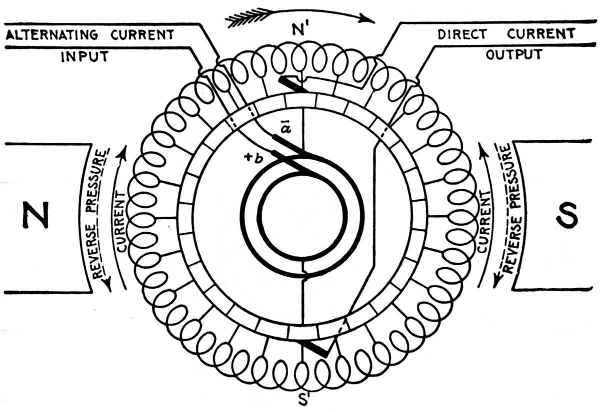
File Rotary Converter Single Phase To Dc Png Wikimedia Commons
Collection of 3 phase rotary converter wiring diagram. A wiring diagram is a streamlined standard photographic depiction of an electric circuit. It shows the elements of the circuit as simplified shapes, and the power and also signal connections between the tools.

How To Build A Rotary Three Phase Converter With Details Parts Youtube
Rotary Phase Converter Wiring Diagram. wiring diagram for loads that american rotary total up to 3 phase idler motor t1 t2 t3 wiring diagram for paralleling multiple phase converters using a transfer switch note all wiring must be done by a licensed phase a matic inc rotary phase converter installation 230v "r" series rotary converter is 230v single phase in single unit installation diagram ...
Phoenixphaseconverters Com
American Rotary's engineering departments spent over 2 years engineering the perfect generator for a Rotary Phase Converter, and its patent technology is the best in the industry. American Rotary's custom generator is one of a kind in our industry and outperforms the standard motor/idlers found on a typical phase converter. Designed for Phase Converters. American Rotary's custom designed ...
How To Install H A S Rotary Phase Conversion System
Ac Series Tru Wave Tm Phase Converter Pages 1 3 Flip Pdf Fliphtml5. H a s rotary phase conversion system how does static converter work electrician talk to wire single three auto start wiring diagram up 30hp 3 hp 9 on matic inc in general board building output voltage of practical machinist largest diagrams quest ac series tru wave tm installation and operation manual pony dual t type 5l ...

25 Best Looking For 3 Phase Rotary Converter Wiring Diagram Stephan Fuchs
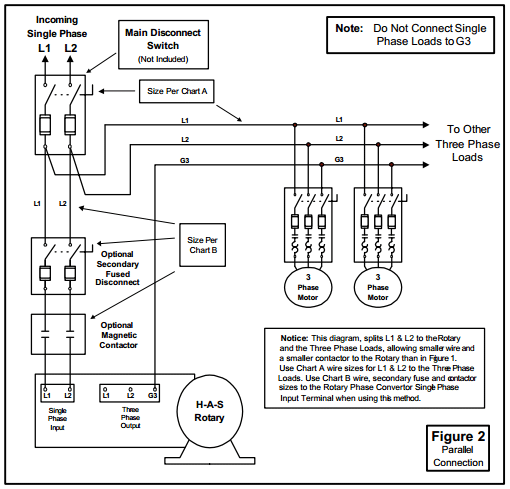
Install the H-A-S Rotary according to the appropriate wiring diagram (Figure 1 or 2). Incoming power (L1 & L2) should be connected through the main disconnect switch and connected to the rotary terminal block, terminals 1 & 2. Install the system lines L1, L2, & G3. These may be connected to a three phase distribution panel or looped from motor ...
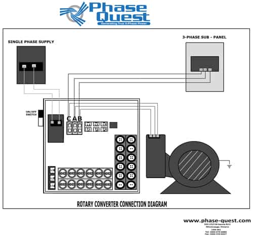
Wiring Diagrams Phase Quest Inc Phase Quest Inc
Description: Laser Hobbyists - Hobby Archives - Www.laserfx with regard to Rotary Phase Converter Wiring Diagram, image size 625 X 742 px, and to view image details please click the image.. Here is a picture gallery about rotary phase converter wiring diagram complete with the description of the image, please find the image you need.

Building A Phase Converter Metalwebnews Com
Moulded case circuit breaker series launched in 1993, was available in different versions and is now obsolete. SACE Isomax S series ranged from S1 to S8 with rated uninterrupted currents I u from 125 to 3200A with ultimate rated breaking capacity I cu from 10 to 200kA (380-415V). These devices were developed for AC and DC distribution and were available in fixed, plug-in and withdrawable version.
44 Best Phase Converter Ideas Electrical Wiring Electrical Circuit Diagram Electrical Projects
Rotary 3 Phase Converter Wiring Diagram - heretup. Collection of 3 phase rotary converter wiring diagram. A wiring diagram is a streamlined standard photographic depiction of an electric circuit. It shows the elements of the circuit as simplified shapes, and the power and also signal connections between the tools. 3 Phase Converter Wiring Diagram.
Americanrotary Com
Installation diagrams and videos. Rotary Phase Converter DIY. Please note that copies of wiring diagrams are usually available from your manufacturer and first, I will include a list of some owner's manuals that I found online: E-Z phase. Phase Converter from American Rotary and this is the manual. AR General Duty.
Three Phase Inverter Circuit Diagram Diy Electronics Projects
Get 24⁄7 customer support help when you place a homework help service order with us. We will guide you on how to place your essay help, proofreading and editing your draft – fixing the grammar, spelling, or formatting of your paper easily and cheaply.

Phase A Matic Wiring Diagram Anisfamy
Size: 113.87 KB. Dimension: 720 x 376. DOWNLOAD. Wiring Diagram Images Detail: Name: american rotary phase converter wiring diagram - 3 Phase Rotary Converter Wiring Diagram Beautiful Pretty American Rotary Phase Wiring Diagram Electrical. File Type: JPG.
Laser Hobbyists Hobby Archives Www Laserfx Com
Cr Cul Listed Rotary Phase Converter Toews Power Systems

Rotary Phase Converter Connection Diagram Electrical Projects Home Electrical Wiring Electrical Diagram
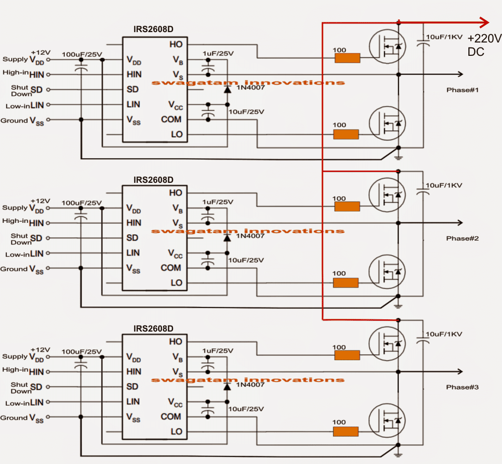
Simple 3 Phase Inverter Circuit Homemade Circuit Projects
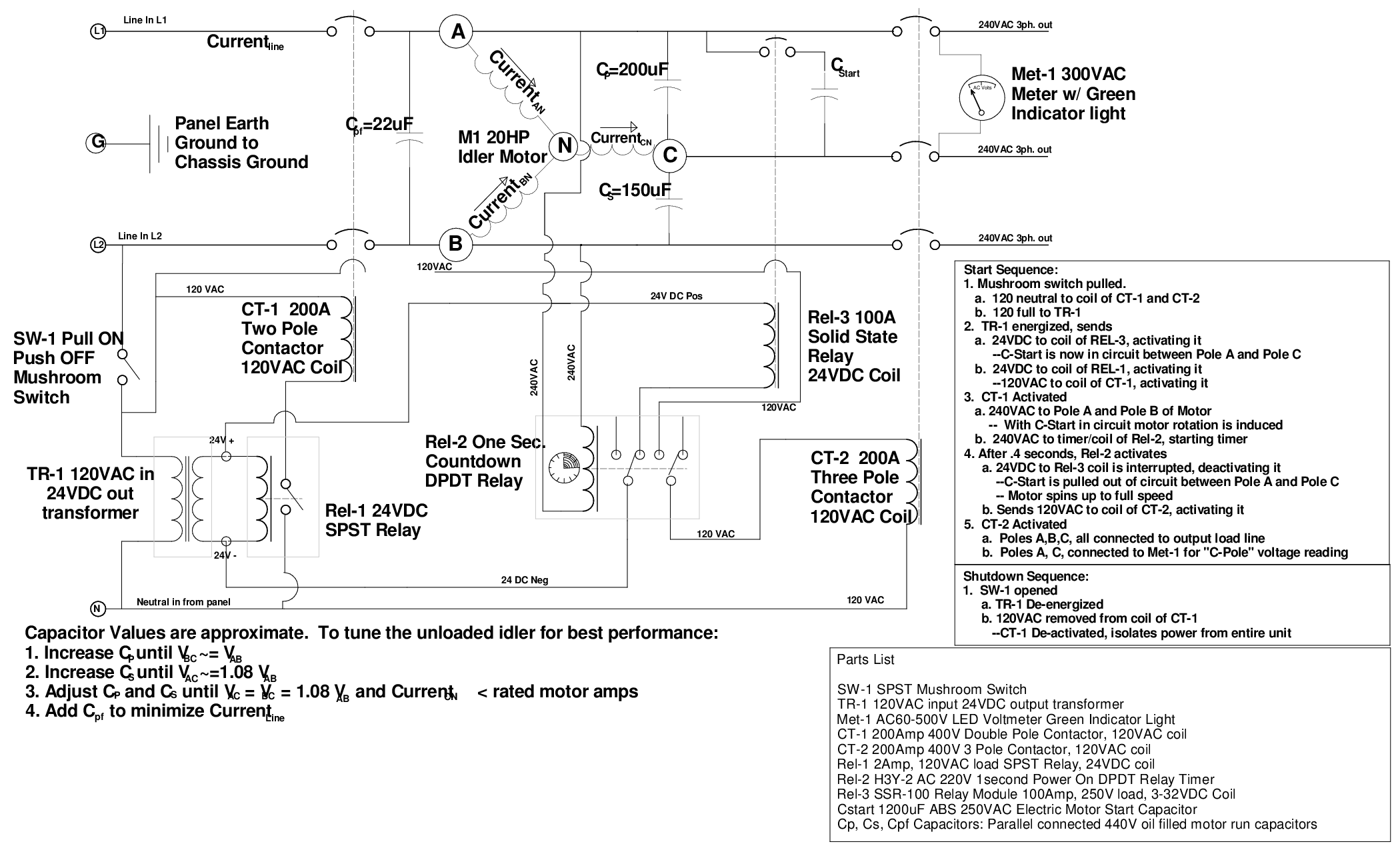
How To Build A Rotary Phase Converter Homemadetools Net
Phase A Matic Rotary Converter Installation Instructions
Powercapacitors Co Uk
0 Response to "38 rotary phase converter wiring diagram"
Post a Comment