38 iron carbon phase diagram
Hypereutectoid steel: has a carbon content greater than the eutectoid 8 Example: Phase Equilibria For a 99.6 wt% Fe-0.40 wt% C at a temperature just below the eutectoid, determine the following a) composition of Fe 3C and ferrite (α) b) the amount of carbide (cementite) in grams that forms per 100 g of steel The primary phase of low-carbon or mild steel and most cast irons at room temperature is ferromagnetic α-Fe. It has a hardness of approximately 80 Brinell. The maximum solubility is about 0.02 wt% at 727 °C (1,341 °F) and 0.001% carbon at 0 °C (32 °F). When it dissolves in iron, carbon atoms occupy interstitial "holes". Being about twice the diameter of the tetrahedral hole, the carbon ...
Click here to download pdf notes NOW - http://bit.ly/3lggovpIron Carbon DiagramIron Iron Carbide DiagramIron Carbon Phase Diagram ExplanationIron Carbon Equ...

Iron carbon phase diagram
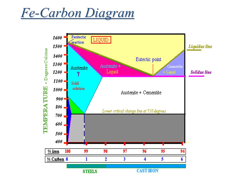
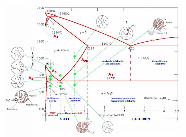
The Iron-Carbon Diagram: A map of the temperature at which different phase changes occur on very slow heating and cooling in relation to Carbon, is called Iron- Carbon Diagram. Iron- Carbon diagram shows - the type of alloys formed under very slow cooling, proper heat-treatment temperature and how the properties of steels and cast irons Jun 01, 2012 · Dr. Dmitri Kopeliovich Iron-carbon phase diagram describes the iron-carbon system of alloys containing up to 6.67% of carbon, discloses the phases compositions and their transformations occurring with the alloys during their cooling or heating.. Carbon content 6.67% corresponds to the fixed composition of the iron carbide Fe 3 C. . The diagram is presented in the picture: Simplified Iron-Carbon phase diagram austenite ↔ pearlite (mixture of ferrite & cementite) The Austenite to ferrite / cementite transformation in relation to Fe-C diagram. MICROSTRUCTURE OF AUSTENITE. MICROSTRUCTUREOF PEARLITE Photomicrographs of (a) coarse pearlite (b) fine pearlite . 3000X.
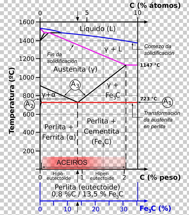
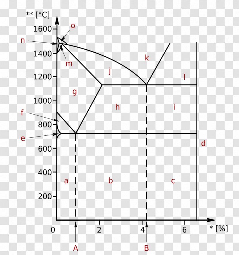
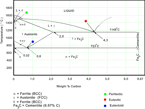
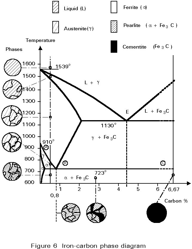
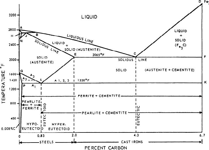
Iron carbon phase diagram. This iron carbon phase diagram is plotted with the carbon concentrations by weight on the X-axis and the temperature scale on the Y-axis. The carbon in iron is an interstitial impurity. The alloy may form a face centred cubic (FCC) lattice or a body centred cubic (BCC) lattice. It will form a solid solution with α, γ, and δ phases of iron. The iron–iron carbide (Fe–Fe 3 C) phase diagram. The percentage of carbon present and the temperature define the phase of the iron carbon alloy and therefore its physical characteristics and mechanical properties. The percentage of carbon determines the type of … The iron-carbon phase diagram showing the eutectic and eutectoid reactions. Reproduced with the permission of Jud Ready of the Georgia Tech. Joint Student Chapter of ASM/TMS. Grey cast irons are softer with a microstructure of graphite in transformed-austenite and cementite matrix. The graphite flakes, which are rosettes in three dimensions ... The Iron–Iron Carbide (Fe–Fe3C) Phase Diagram In their simplest form, steels are alloys of Iron (Fe) and Carbon (C). The Fe-C phase diagram is a fairly complex one, but we will only consider the steel part of the diagram, up to around 7% Carbon.
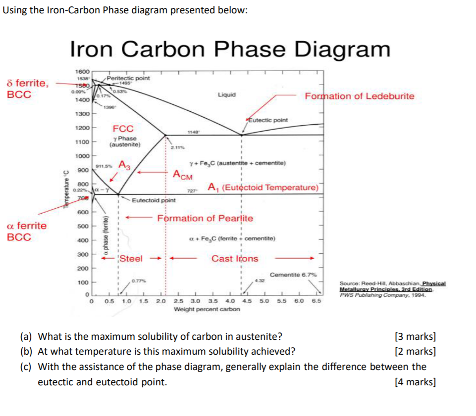
Iron bromide-water. The phase diagram covers the temperature range from minus 40 to 140 °C. The solid phases are ice and the nonahydrate, hexahydrate, tetrahydrate and dihydrate of iron bromide. Sodium hydroxide – phosphoric acid – water. The solubility phase diagram at 60 °C is shown. Many solid phases appear in this phase diagram. (b) In Iron-Carbon phase diagram, we can see that the maximum concentration of Carbon is 6.67%. This is due to the fact that maximum solubity of carbon in iron is 6.67% as it forms iron carbide (Fe3C form). After 6.67 percentage,there is no applicati… View the full answer The Iron Carbon Phase Diagram There is more to the iron-carbon phase diagram than related in the backbone. In particular, there is some nomenclature that I avoided in the main text but that is important for understanding other writings about iron and steel. A. Phase Diagrams 1. Iron-Copper System The iron-copper phase diagram, taken from Hansen,3 is presented in Figure 1. Hansen3 also gives a thorough review of the work done on the system up to 1957. A review of more recent work, up to 1963 was done by . Elliott~ The most recent version of the phase diagram
Iron/Carbon Phase Diagram Iron shows a eutectic with Carbon allowing for a lower melting alloy Body Centered Tetragonal. 6. 7. 8 Carbon content can be reduced by reaction with oxygen and stirring. 9. 10 Eutectoid Steel Pearlite. 11 Time-Temperature-Transformation Diagram. 12 Time-Temperature-Transformation Diagram Mar 11, 2013 · Fig 1 Iron carbon phase diagram. C is an interstitial impurity in Fe. It forms a solid solution with alpha, gamma and delta phases of iron. Maximum solubility of C in alpha iron is 0.025 % at 727 deg C. Body centred cubic (BCC) iron has relatively small interstitial positions. Iron-Carbon Phase Diagram with Detailed Explanation: If the percentage of the carbon is in the range of 0 to 2.11 % then it is called Steel and if the percentage of carbon is in the range of 2.11 to 6.67% then it is called Cast iron. As the carbon content increases, it produces more Iron-Carbide volume and that phase will exhibit high hardness. The iron-carbon system (steel and cast iron) MSE 2090: Introduction to Materials Science Chapter 9, Phase Diagrams 2 Component - chemically recognizable species (Fe and C
Simplified Iron-Carbon phase diagram austenite ↔ pearlite (mixture of ferrite & cementite) The Austenite to ferrite / cementite transformation in relation to Fe-C diagram. MICROSTRUCTURE OF AUSTENITE. MICROSTRUCTUREOF PEARLITE Photomicrographs of (a) coarse pearlite (b) fine pearlite . 3000X.
Jun 01, 2012 · Dr. Dmitri Kopeliovich Iron-carbon phase diagram describes the iron-carbon system of alloys containing up to 6.67% of carbon, discloses the phases compositions and their transformations occurring with the alloys during their cooling or heating.. Carbon content 6.67% corresponds to the fixed composition of the iron carbide Fe 3 C. . The diagram is presented in the picture:
The Iron-Carbon Diagram: A map of the temperature at which different phase changes occur on very slow heating and cooling in relation to Carbon, is called Iron- Carbon Diagram. Iron- Carbon diagram shows - the type of alloys formed under very slow cooling, proper heat-treatment temperature and how the properties of steels and cast irons

Please Answer The Following Question Regarding The Iron Iron Carbide Phase Diagram A Carefully Draw And Label The Phase Diagram Of Iron And Carbon Alloy Up To 6 Carbon Contents B For Pure

Materials And Metallurgical Engineers World The Iron Carbon Phase Diagram Describe Fe C Diagram There Is More To The Iron Carbon Phase Diagram Than Related In The Backbone In Particular There Is Some
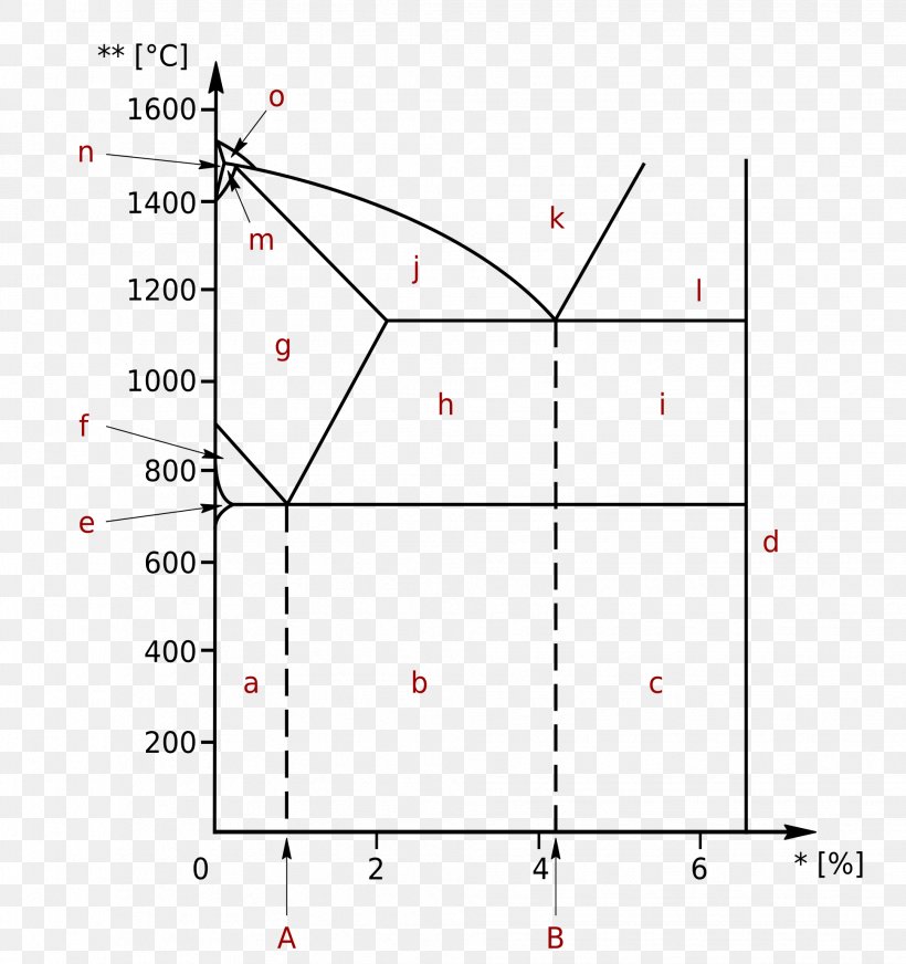
Iron Carbon Phase Diagram Cementite Triple Point Png 1938x2063px Phase Diagram Area Carbon Cementite Chemical Equilibrium
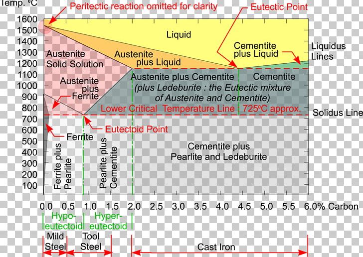
Iron Carbon Phase Diagram Steel Cementite Png Clipart Angle Area Austenite Carbon Carbon Steel Free Png

Can Someone Explain Me About This Iron Carbon Phase Diagram Which Is Beyond 6 67 Wt C Askmemetallurgy










0 Response to "38 iron carbon phase diagram"
Post a Comment