38 electric strike wiring diagram
electric strike Diagram 2 A mortise lock aligned with its centerline 3/8" below the centerline of the electric strike. 2) The depth and positioning of the electric strike cavity. It is important to select an electric strike with the correct cavity depth to accommodate the lock. Many electric strikes have shallow cavities and wiring diagram LBM ® If the answer is 12-16* Volt continue to step 6. If the answer its 24 volt please follow the instructions below. What does the strike wiring configuration need to be? *For 16 Volt AC/DC operations Maintain the solenoid wiring configured for 12 - 16 V. Be advised that with a 16 Volt source, the Model 5000 is capable of a 10 ...
1500 Series or 1600 Series Electric Strike 1500 Series and 1600 Series Electric Strikes Installation Instructions 1 Product Components Specifications 1 2 3 ASSA ABLOY, the global leader in door opening solutions 3 1 2 Pigtails (12 VDC and 24 VDC) Trim Enhancer MINIMUM WIRE GAUGE REQUIREMENTS VOLTAGE 12VDC 24VDC Solenoids are rated at +/- 10% ...

Electric strike wiring diagram
P:\INSTALLATION INST\ELECTRIC STRIKE\INST-30-4.vsd Rev - 01/11 Page 3 Solenoid Solenoid 30-4 Series LCBM Wiring Diagram 30-4 Series LCBMA Wiring Diagram N/O C N/C ORANGE BROWN PURPLE Auxiliary Switch (LBM) 7 5 8 Electrical Ratings for ALL 30-4 Electric Strike Solenoids Resistance in OHMS +/-10% 6.2 23.5 500 6.2 23.5 96.0 380 1200 Electric Strike Wiring Diagram– wiring diagram is a simplified enjoyable pictorial representation of an electrical circuit.It shows the components of the circuit as simplified shapes, and the skill and signal associates amid the devices. Common wiring diagrams. Resolution: The following common wiring diagrams are available:One Single Door with Panic BarElectric Latch Retraction, with Auto OperatorDelayed egress - Fire Rated ApplicationAuto Operator and actuatorElectr... Resolution: Electronic Protocols:Access Control Door with electric trimAccess Control with electric strike ...
Electric strike wiring diagram. electric door strike wiring diagram . electric door strike wiring diagram . fast trac form . riser drawings for auto operators . Common Wiring D . quote request form . can automatic door opener work with and card reader strike . quote request form ... Electric Door Strike Wiring Diagram - wiring diagram is a simplified normal pictorial representation of an electrical circuit. It shows the components of the circuit as simplified shapes, and the capacity and signal associates in the midst of the devices. A wiring diagram usually gives guidance not quite the relative face and promise of ... Hes 51wk Electric Strike Wiring Diagram - One of the most hard automotive repair tasks that a mechanic or repair shop can acknowledge is the wiring, or rewiring of a car's electrical system.The trouble really is that every car is different. similar to bothersome to remove, replace or fix the wiring in an automobile, having an accurate and detailed Hes 51wk Electric Strike Wiring Diagram is ... Electric Strike Kit: https://amzn.to/2VjiwogExtra Push Entry Clickers:https://amzn.to/2EbUAfzLow Voltage Wire: https://amzn.to/2EvMuQkIn this video we show y...
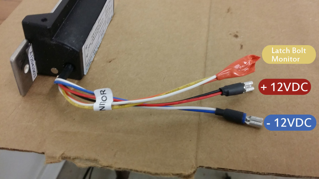
Blue Wire VOLTAGE AND WIRING ELECTRIC STRIKE ATTACHMENT 1. Before installing the strike, make the necessary wire connections. Refer to the table below in. (Fig. 7) for ESK/ESP strikes. for latch/deadbolt and monitor on ESP strikes only. 2. When you are installing the strike into the frame cut-out (Fig. 3, page 06), tuck the Hes 5000 Series Electric Strike Wiring Diagram Sample. hes 5000 series electric strike wiring diagram - What's Wiring Diagram? A wiring diagram is a type of schematic which utilizes abstract pictorial signs to show all the affiliations of elements in a system. Wiring layouts are made up of 2 points: icons that represent the elements in the circuit,… This electric strike ships as 12V. If you need to convert the unit from 12V to 24V, see Diagram 2. 2. If your strike is supplied with the LATCHBOLT MONITOR (LBM), or LATCHBOLT STRIKE MONITOR (LBSM), see Diagrams 3 & 4 for wiring instructions. 3. For available faceplate options, see page 4. Prepare Strike a To prevent electric shorting ... SERIES HEAVY DUTY ELECTRIC STRIKES Hanchett Entry Systems, Inc. N. 17th Ave. Phoenix, AZ diagramweb.net Wiring diagram for 12/24 volts FIG. A 12 VOLT DC FIG. B 24 VOLT DC NOTE: The is supplied as a 12 volt DC unit. For 24 volts DC, see figure B. INSTRUCTIONS: 1. Cut the violet and black wires. 2.
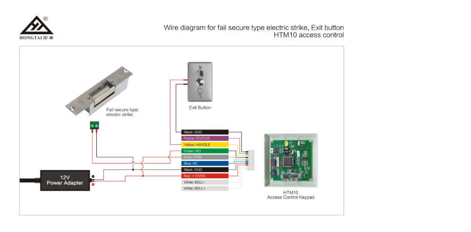
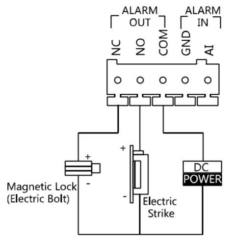
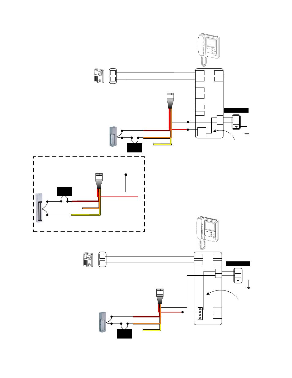
Nov 09, 2021 · Electric strike wiring diagram. A first consider a circuit representation might be complicated however if you could. It shows the components of the circuit as simplified. 12V to 24V Conversion Diagram 2. Electric Strike Wiring Diagram wiring diagram is a simplified enjoyable pictorial representation of an electrical circuit. GSC3570 Connection & Wiring Diagrams - "Fail Secure" Electric Strike, POE Power Supply Outdoors-+ Fail Secure Electric Strike Door Connect Indoors Motion Sensor-+ S Power Supply 12V GND Exit Button +12V GND IN+ AIN1 NC1 AIN3 AIN2 COM1 NO1 GND POE power supply 802.3af 12.5W IN + Active voltage range 9-15V POE Switch Electric Door Strike Wiring Diagram. Collection of electric door strike wiring diagram. A wiring diagram is a simplified traditional pictorial representation of an electrical circuit. It reveals the parts of the circuit as simplified forms, and also the power as well as signal links between the gadgets. A wiring diagram normally offers information about the… magnetic lock or fail safe strike with button, keypad, PIR and touch sense bar or micro-switch bar wired in series N/C PIR Power Supply for fail safe strikes and magnetic locks should be DC. If this is not available you may use an AC power source an d wire inline a “Full Wave Bridge” rectifier. This will convert the AC to DC.
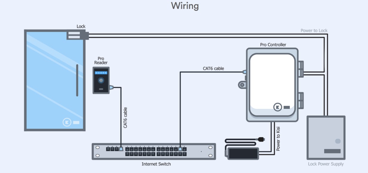
Standalone Fail Secure Electric Lock Kisi Support
Jul 07, 2019 · A wiring diagram is an easy visual representation of the physical connections and physical layout of your electrical system or circuit. It shows the way the electrical wires are interconnected which enable it to also show where fixtures and components could be coupled to the system.
China European Short Type Fail Secure No Door Strike Electric Strike Electric Lock Status Output Dc12v On Global Sources Electric Strike Striker Door Strike
typical electric strike wiring diagram intermittent/continuous duty 24 vdc black : common white : no red : nc color code: field reversible (fail secure) to fail safe fail secure configuration field reversible (fail safe) to fail secure fail safe configuration wire coding (monitored version) fail secure to fail safe step 1 loosen screw (b) approximately

Access Control Cables And Wiring Diagram Kisi
Adams Rite Electric Strike Wiring Diagram Sample. adams rite electric strike wiring diagram - A Beginner s Overview of Circuit Diagrams A first consider a circuit representation might be complicated, however if you could read a train map, you can check out schematics. The objective is the same: obtaining from point A to aim B. Literally, a…

Wiring For A Fail Secure Configuration
We show you how an electric strike works with a remote door opener and a push to exit button. This is a simple electric strike setup with a manual push to ex...

Door Strikes
Search Wiring Diagrams for HES and Securitron products. Use the fields below to narrow down your search. You can also view all Wiring Diagrams by leaving the fields blank and clicking the "Search" button. PRO TIP: Be Broad! There are additional filters on the Results page to further narrow down your search.

Dc12v Door Release Electric Strike Electric Bolt Lock Power To Lock Open Door Security For Access Control System Power Electric Power Lockspower Door Lock Aliexpress
HES 8300 Electric Strike. Faceplates & Accessories, Documents, Certifications & Listings. The HES 8300 series is a fire rated, compact, high performance electric strike featuring a unique concealed design for use with cylindrical locksets. No cutting on the frame is required. Simply remove the existing strike plate, adjust the vertical ...
1
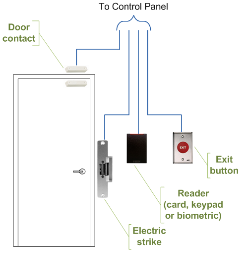
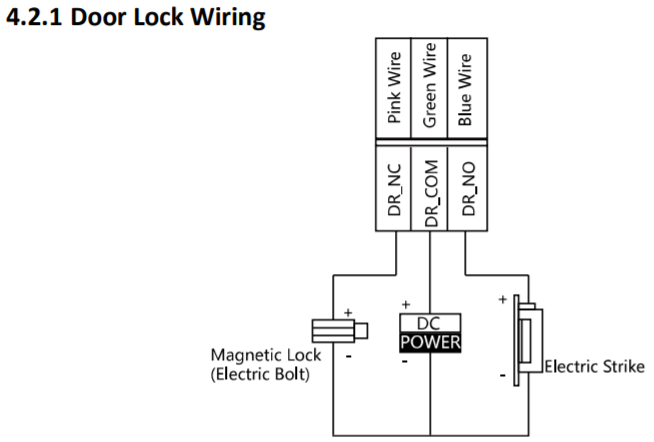
The one in the diagram is a magnetic lock, but the premise is the same for an electric strike. The reader receives the access credentials, sends them to the controller for authentication, and if they are approved, the controller tells the power supply to either give or cut off power to the lock, which opens the door.
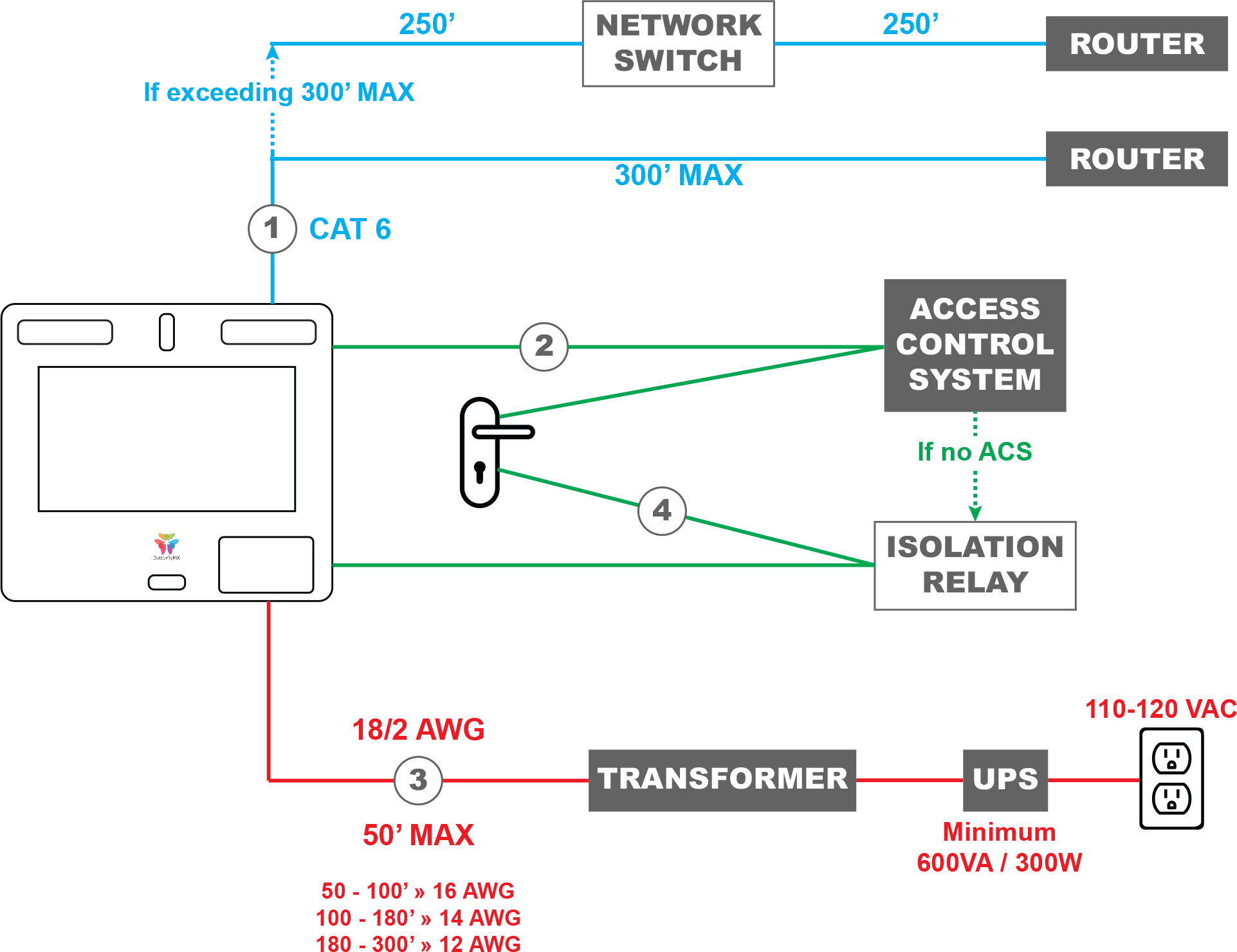
Wiring A Butterflymx Smart Intercom Directly To An Electric Lock Butterflymx
powering a lock, the minimum inductive load (lock) power wire guage shall be determined using the sdc wire guage chart or another voltage drop estimation tool. all wiring (single or multi- conductor) shall be color coded without splices. a minimum of two spare conductors is recommended. 6. voltage may not be specified on these wire diagrams. verify
File Access Control Door Wiring Png Wikipedia
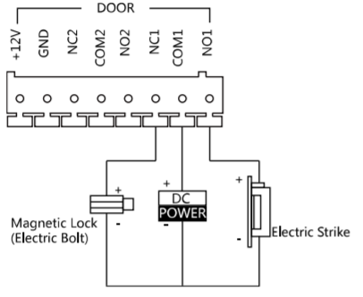
Magnetic Lock Wiring Diagram Much like the door access control system diagram above, the mag lock wiring diagram relies on a few simple basics: electricity supply, switches, and, of course, locks. Magnetic locks , also referred to as mag locks or maglocks for short, rely on a constant flow of electricity to stay sealed.

Fs003
The 9000 Series Electric Strike has back EMF protection built into the product. No external protection diode is required. The wiring diagram for the monitoring schematic is shown in Fig. 4 and on the back of the strike. ASSA ABLOY Australia Pty Limited, 235 Huntingdale Rd, Oakleigh, VIC 3166 ABN 90 086 451 907 ©2008 An ASSA ABLOY Group brand

How Connect An Electric Strike Youtube
as shown in Diagram 2. 3 VioletIF using the Latchbolt Monitor (LBM) or Latchbolt Strike Monitor (LBSM), THEN REFER to Diagrams 5 and 6 to complete wiring (see page 3). Verifying the Operation Mode The HES 9400/9500/9600/9700 Electric Strike is pre-set for FAIL SECURE OPERATION as shown in Diagram 3. 1 VERIFY that both keepers are in

Robert Hoyt Stevenjamesjraz Profile Pinterest
Wiring Diagrams. Sort by 80.0390 - 10ACP12DS Access control package 5 . pdf | 105.19 KB ... Electric Strike and auto flush bolts in active leaf . pdf | 12.48 KB . download; 80.0014 - MC25 Pair of Doors W/ Electric Strike, Manual Flush Bolts . pdf | 14.52 KB . download ...

Olide Electric Strike For Automatic Swing Door Olidesmart
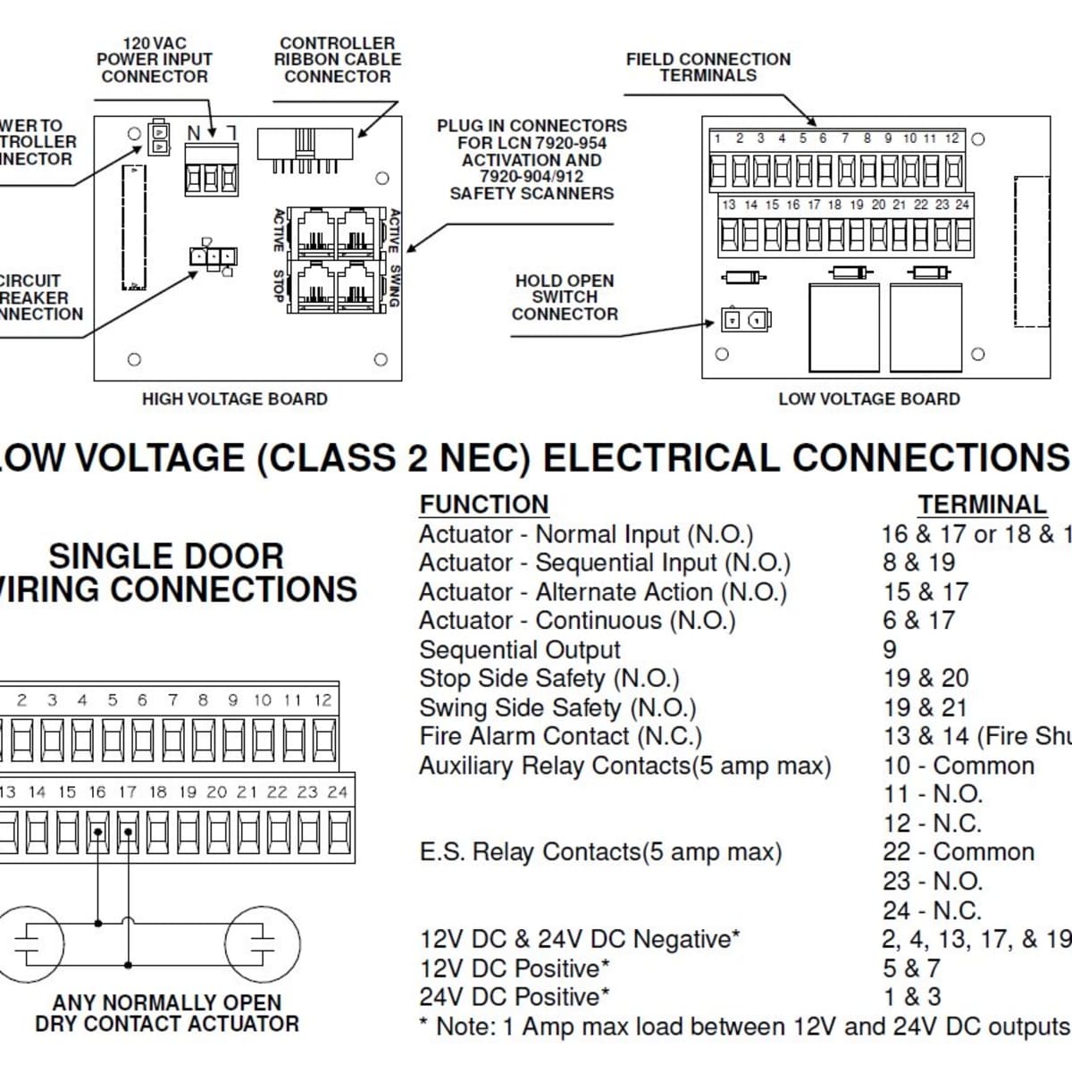
Common wiring diagrams. Resolution: The following common wiring diagrams are available:One Single Door with Panic BarElectric Latch Retraction, with Auto OperatorDelayed egress - Fire Rated ApplicationAuto Operator and actuatorElectr... Resolution: Electronic Protocols:Access Control Door with electric trimAccess Control with electric strike ...
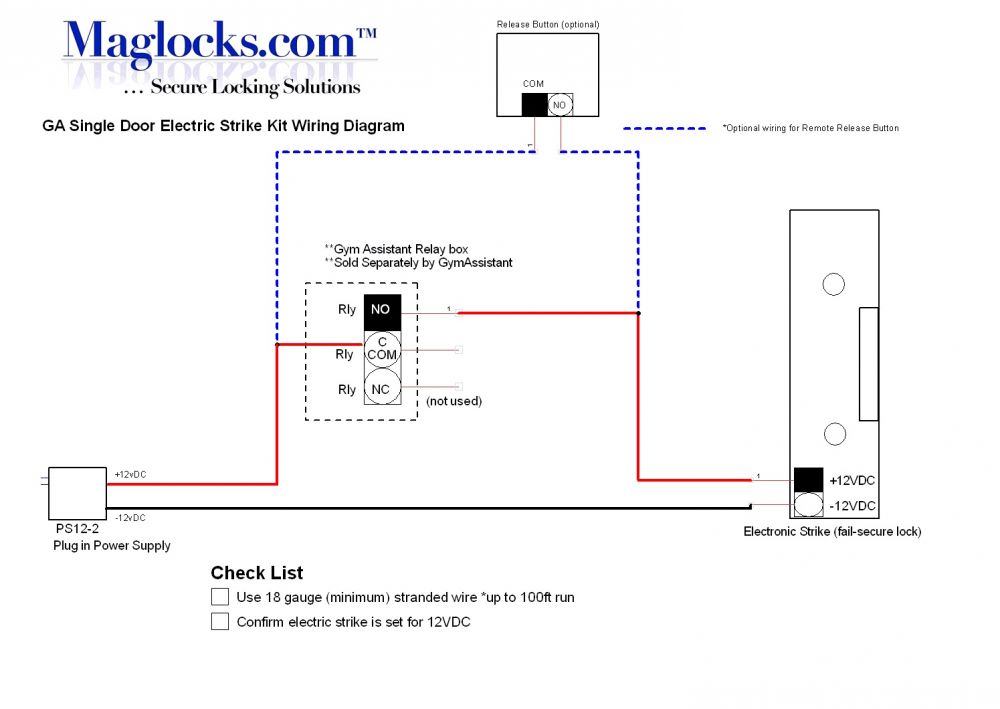
Gym Assistant Door Electric Strike Kit Rim Mount Push Bars
Electric Strike Wiring Diagram– wiring diagram is a simplified enjoyable pictorial representation of an electrical circuit.It shows the components of the circuit as simplified shapes, and the skill and signal associates amid the devices.
Rc 01 Powernet Proximity Reader Controller User Manual Isonas Orporated
P:\INSTALLATION INST\ELECTRIC STRIKE\INST-30-4.vsd Rev - 01/11 Page 3 Solenoid Solenoid 30-4 Series LCBM Wiring Diagram 30-4 Series LCBMA Wiring Diagram N/O C N/C ORANGE BROWN PURPLE Auxiliary Switch (LBM) 7 5 8 Electrical Ratings for ALL 30-4 Electric Strike Solenoids Resistance in OHMS +/-10% 6.2 23.5 500 6.2 23.5 96.0 380 1200

Fs003
Arduino Rfid Door Strike Victorbush

5 Wires Electric Lock Magnetic Output With Timer Dc12v Fail Safe Power Off To Open Door Security For Access Control System Output Aliexpress
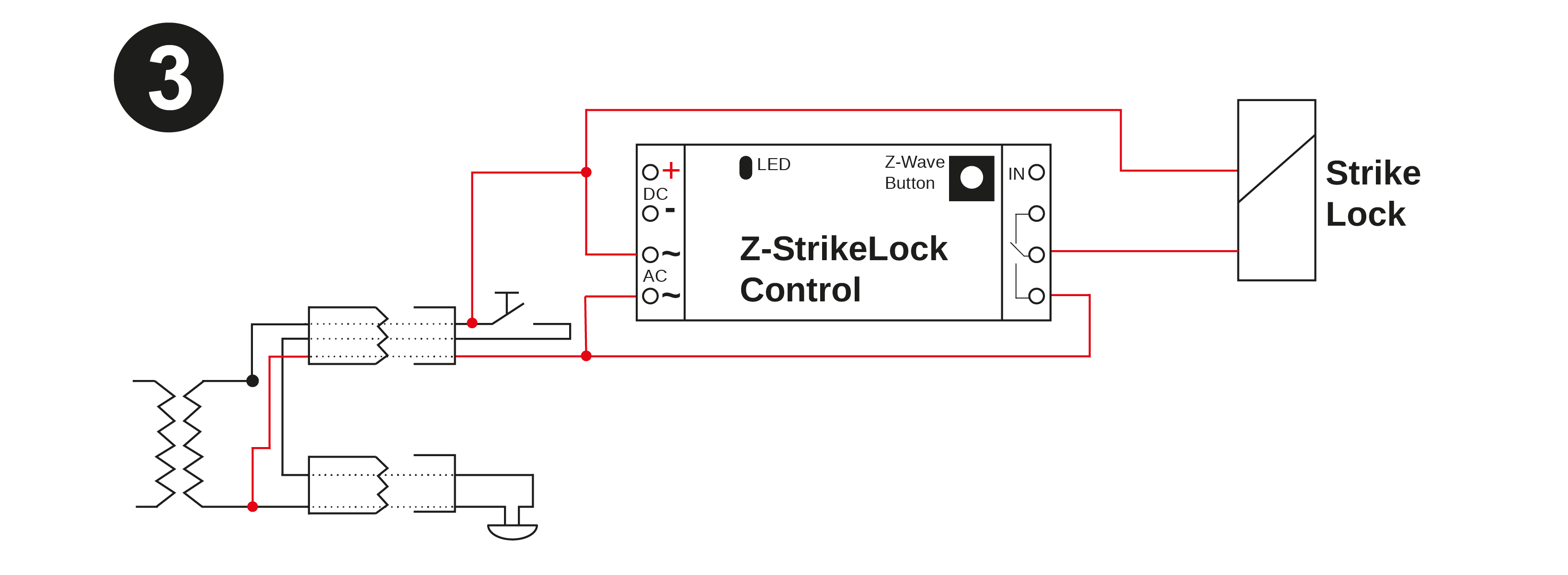
Strike Lock Control

Low Voltage Buzzer For Dc Electric Strikes
Dc12v Dc24v Door Electric Lock For Access Control System Lock Delay Time Is Adjustable Auto Door Electric Lock Olide Autodoor

Hes 9400 Surface Mount Electric Strike Installation Youtube
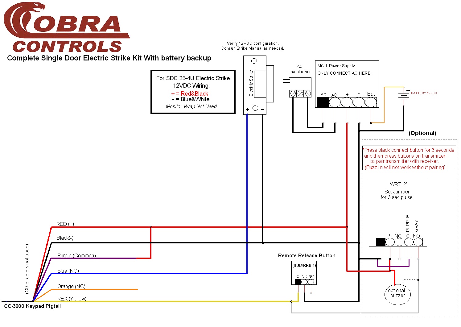
Complete Single Door Electric Strike Kit

Low Volt Wiring Unit 4 School Of Lock And Electronic Security
Wiring Diagram For Sf Vi104e Ip Visiotech
2
How To Coordinate Automatic Doors With Locking Devices Dengarden
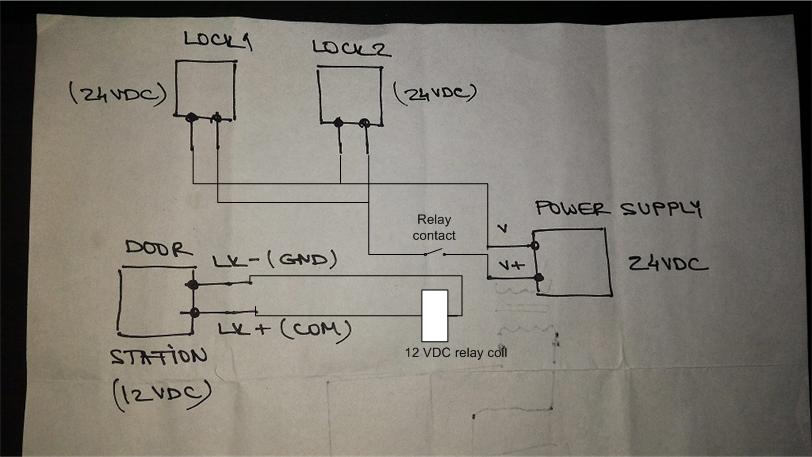
Wiring Help 24vdc Door Strikes To 12vdc Door Station General Access Control Discussion Cctvforum Com
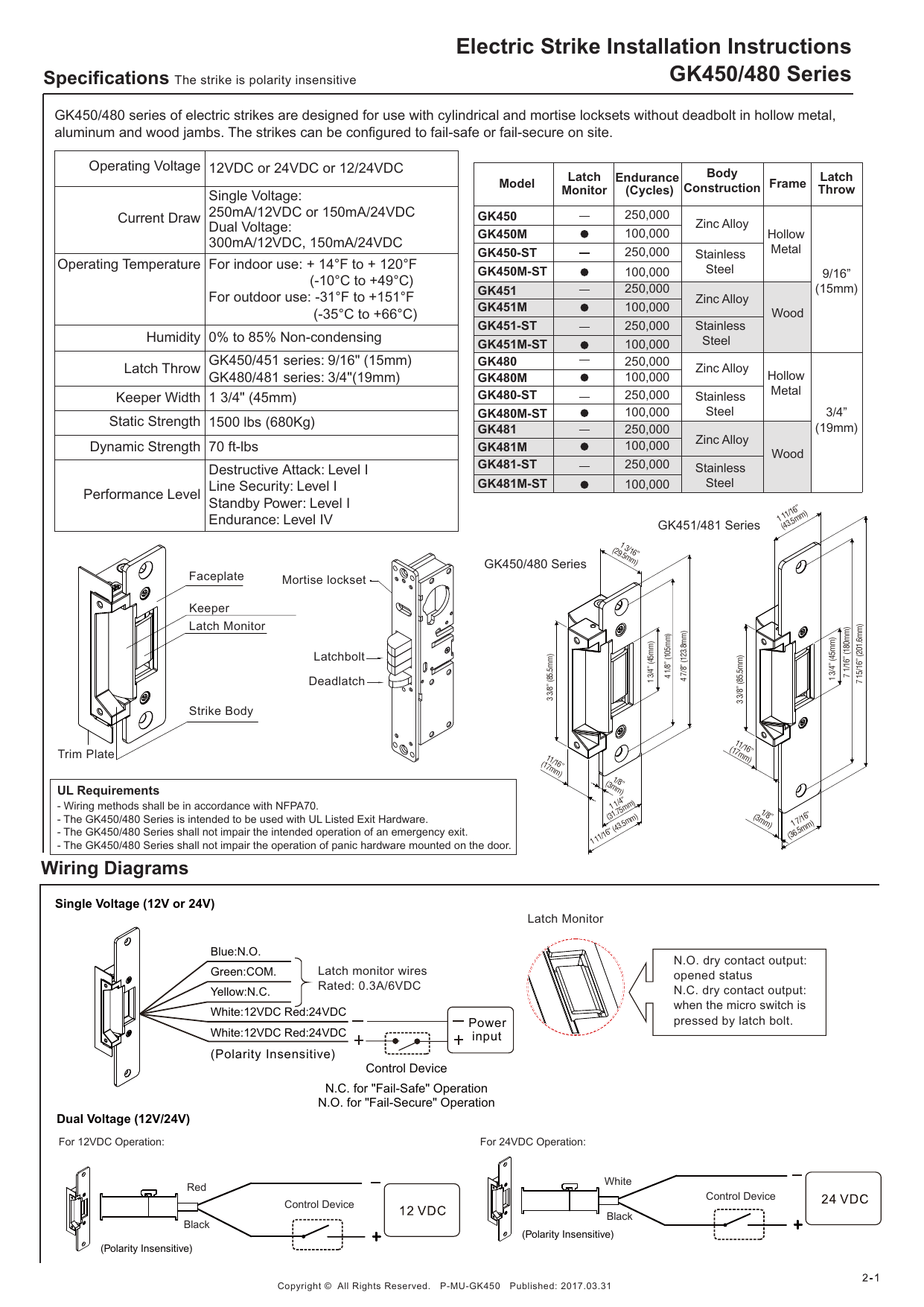
Gianni Industries Gk451 Gk481gk451 St Gk481 St Electric Strike For Cylindrical Deadlatch Locksets For Wood Frames Installation Instruction Manualzz
Hikvision Ip Intercom Lock Wiring Ness Corporation

How To Wire A Door Strike To The Liftmaster El2000 El2000ss Or El25 Telephone Entry System Youtube

Electronic Arduino Electric Strike With Arduino Circuitry Itectec

Electric Strike Lock Hubtechshop Nairobi Kenya

Installation Guide For Noke Door Controller Noke
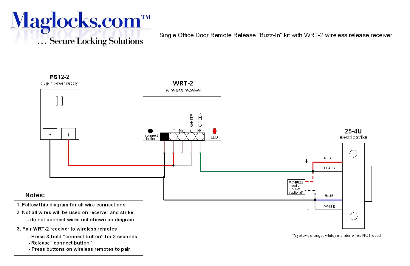
Single Door Remote Buzz In Kit Electric Strike
How To Install An Electric Strike Lock For Doors
Hikvision Ip Intercom Lock Wiring Ness Corporation
Hes 5000 Wiring Diagram Electrical Wiring Diagram Pictures 2020
0 Response to "38 electric strike wiring diagram"
Post a Comment