37 oil tank piping diagram
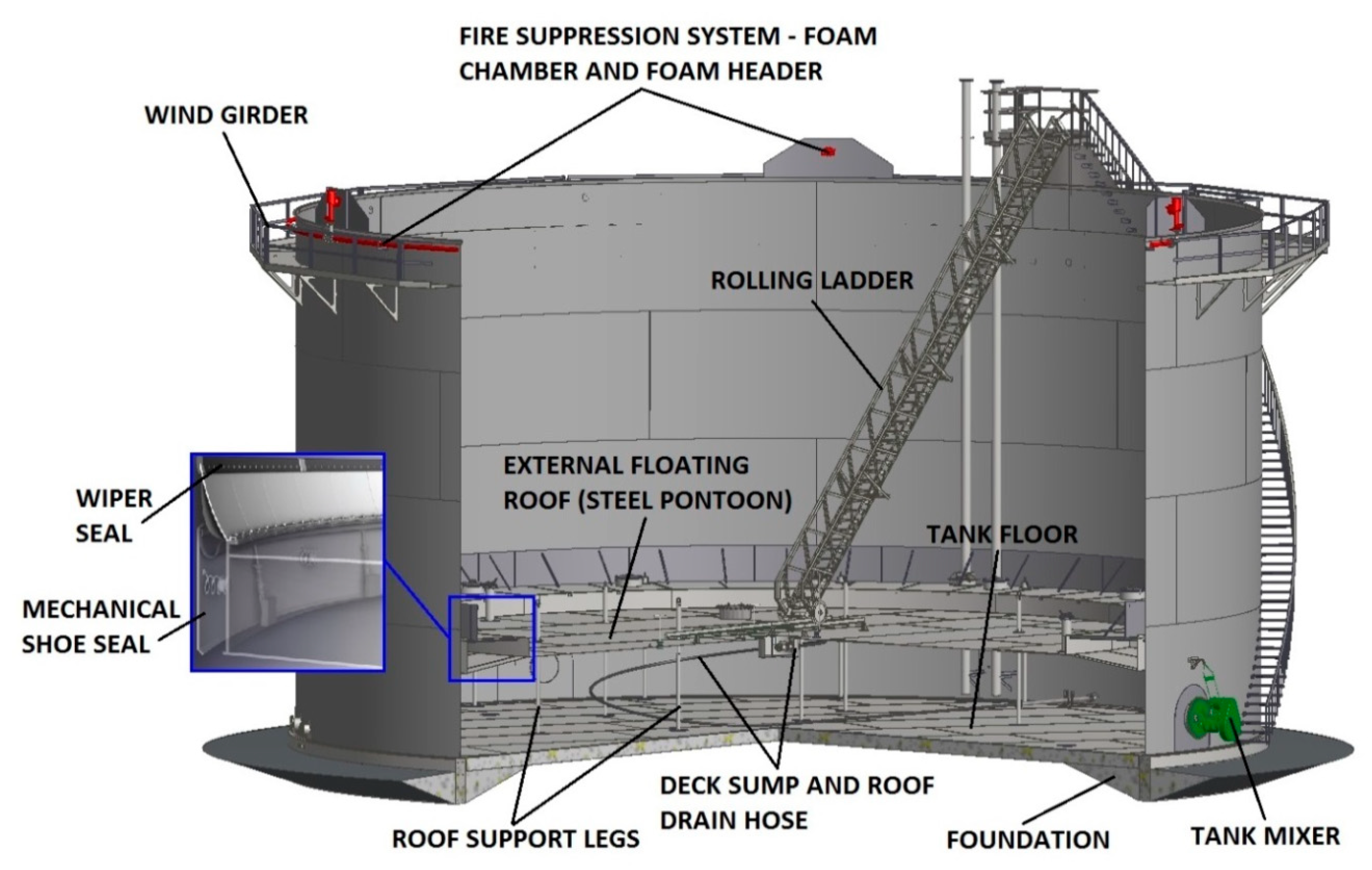
Fig 13– Fuel Supply Piping Using Duplex Tank Bushings ... Figure 2 is a suggested connection diagram only and other connection.22 pages Cone roof tanks: Low pressure tanks for storing petroleum, water, food products, chemicals, and petrochemical products. Floating roof tanks: The roof floats depending on the volume of stored products. Mostly used in oil refineries, such type of tanks reduce fire hazards. Low-temperature storage tanks: Usually store cryogenic fluids line liquefied ammonia, propane, methane, etc.
17 Feb 2010 — Can anybody post a detailed piping set-up for fuel tanks? Thanks!
Oil tank piping diagram
Sealing your Primary Oiler · Oil System Diagram · Very Simplified Oil line Routing · Oil Line Routing · Amsoil Oil Comparison Study · Factory option oil. Shovelhead - Oil line routing on 76 FLH w/stock tank. - Restoring a 76 FLH. Need oil line routing diagram for stock oil tank. My sifton oil pump.Jan 07, · This video was uploaded from an ... NO. 2 OIL TEMPERATURE CONTROL. SYSTEM (TYPICAL-PROVIDE A COMPLETE. SYSTEM FOR EACH ABOVEGROUND. TANK). XHEV. H-. ELECTRIC OIL HEATER H. BPV. FUEL OIL BACK.1 page An Aboveground Storage Tank (AST) Facility or tank farm consists of tanks (including day tanks), piping, secondary containment and ancillary equip-ment. These facilities are used to store fuel that will be dispensed at the site, ... • Valves control the flow of oil between tanks and other tanks, delivery barges and other sources. The most ...
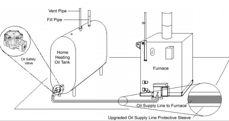
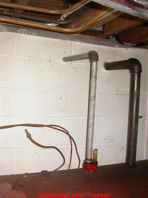
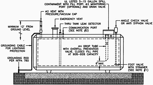
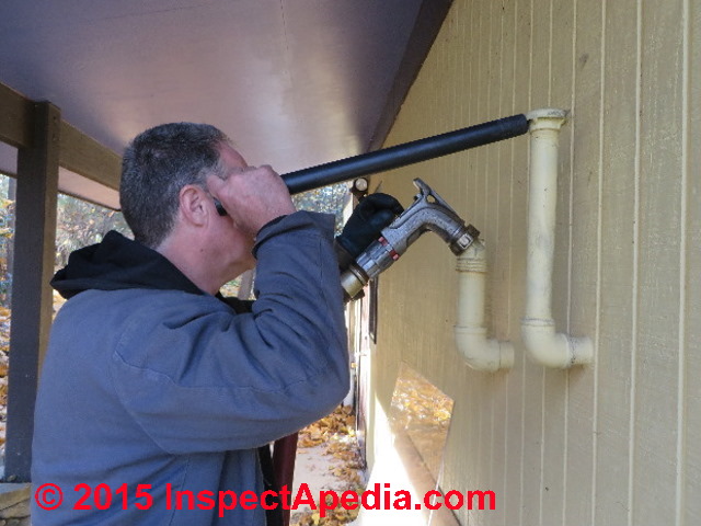
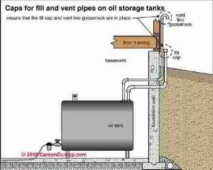
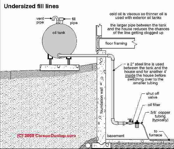
Oil tank piping diagram. Oil Tanks and Piping Chapter 3 Chapter 3—Oil Tanks and Piping 3-3 Introduction The comfort, cleanliness and efficiency of today’s oilheat systems rely on clean, uncontaminated fuel reaching the oilburner. To achieve this: • Install tanks properly. • Maintain tanks by regularly inspecting them and fixing minor defects before tion, construction and repair of fuel-oil storage and piping systems. ... 1301.4 Fuel tanks, piping and valves. The tank, piping and. The oil tank filler pipe is connected to the first oil tank (the rear tank of the pair in our photo) at an oil tank top inlet fitting accepting a 2" diameter filler pipe. A second tank top tapping is used to continue the same diameter 2" steel piping out of the top of tank 1 and into the top of tank 2. checklist can aid you in proper maintenance of your heating oil aboveground storage tank system (AST). DIAGRAM OF A TYPICAL HEATING OIL AST SYSTEM . INSPECTION CHECKLIST . Ask the following questions and if the answer to any of them is "NO," contact your oil dealer or burner technician.
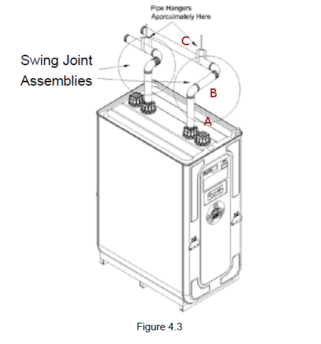
twin tanks 2" fill into tank 1, 2" transfer from top of tank 1 to top of tank 2 using swing joints & union, 2" vent from tank 2. I also suggest if you are using 2 pipe burner piping, you pipe into tank 2 not 1. possible comp ftg leak in tank 1, also tie tanks together at bottom. hope this helps, and if there are better ways out there, I would love to here them. 1305.6 [Heating Oil Storage Tank] Fill piping. Fill piping shall comply with the requirements of Sections 1305.6.1 through 1305.6.6. 1305.6.1 Size. Fill piping shall be a minimum of 2 inches (51 mm)in diameter or 3 inches (76 mm)for No. 6 fuel oil. 1305.6.2 Termination location. 13. Wire the tank or system/pipe sensor connected to the DHW sensor terminals on the follower boiler addressed as #1. 14. The system/pipe sensor must be placed on common piping to the tank, as close to the tank as possible. 15. The system/pipe sensor is wired to the system sensor terminals on the master boiler. Each air pipe from a double bottom tank, deep tanks which extend to the ship’s side, or any tank which may be run up from the sea, is led up above the bulkhead deck. From oil fuel and cargo oil tanks, cofferdams, and all tanks which can be pumped up, the air pipes are led to an open deck, in a position where no danger will result from leaking ...
An Aboveground Storage Tank (AST) Facility or tank farm consists of tanks (including day tanks), piping, secondary containment and ancillary equip-ment. These facilities are used to store fuel that will be dispensed at the site, ... • Valves control the flow of oil between tanks and other tanks, delivery barges and other sources. The most ... NO. 2 OIL TEMPERATURE CONTROL. SYSTEM (TYPICAL-PROVIDE A COMPLETE. SYSTEM FOR EACH ABOVEGROUND. TANK). XHEV. H-. ELECTRIC OIL HEATER H. BPV. FUEL OIL BACK.1 page Sealing your Primary Oiler · Oil System Diagram · Very Simplified Oil line Routing · Oil Line Routing · Amsoil Oil Comparison Study · Factory option oil. Shovelhead - Oil line routing on 76 FLH w/stock tank. - Restoring a 76 FLH. Need oil line routing diagram for stock oil tank. My sifton oil pump.Jan 07, · This video was uploaded from an ...
Processes Free Full Text Applied Cleaning Methods Of Oil Residues From Industrial Tanks Html

Fuel Oil System In Ship For Marine Diesel Engine Marinerspoint
Search Q Underground Oil Tank Vent Pipe Tbm Isch

Single And Double Fuel Tank Piping Diagram Heating Help The Wall
Pitching Tank Fill And Vent Pipes Heating Help The Wall
2
Marine Piping Systems
Oil Lines In Concrete Why They Need To Be Replaced Ed S Garage

Brake Piping Brake Oil Tank And Rerated Parts Wheel Loader Komatsu Wa1200 3 Operator S Compartment And Control System 777parts

Heating Oil Piping Defects Leaks Where Heating Oil Leaks Occur Why How To Find Them How To Fix Them

Piping And Instrumentation Diagram Of The Test Plant Acronyms Download Scientific Diagram

Marine Sea Time Fuel Oil Line Diagram And Explanation In Ship

Figure 2 11 Lubricating Oil System Piping Diagram
Oil Tank Fill Vent Piping Installation Inspection
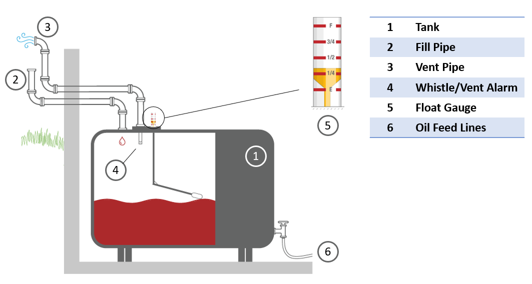
How An Oil Tank Works Smart Oil Gauge
2
Installation
Oil Tank Fill Vent Piping Installation Inspection
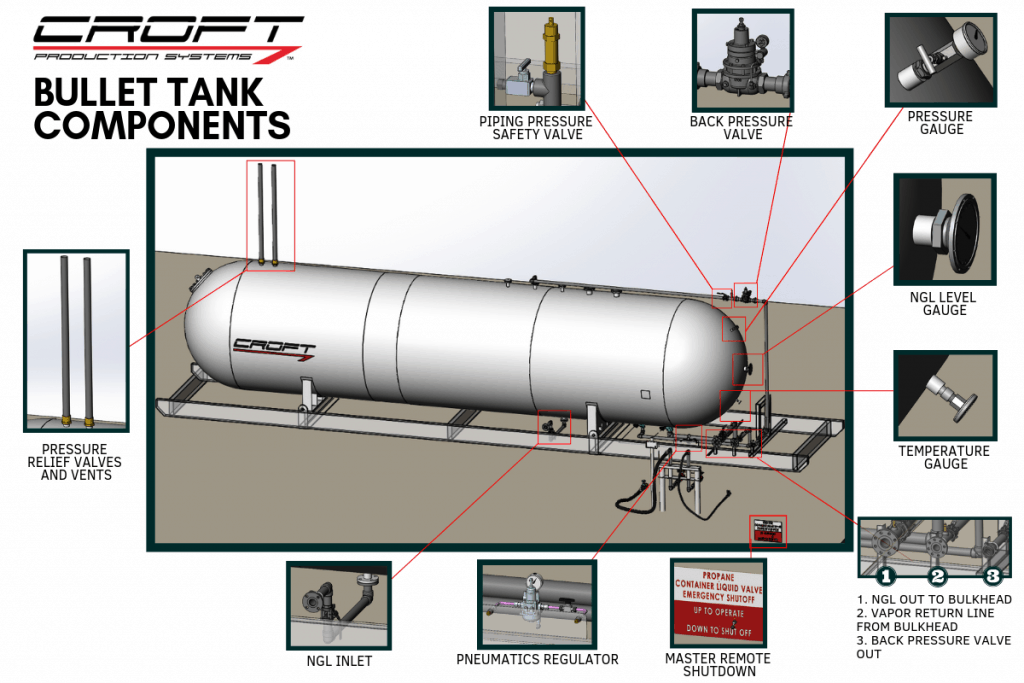
What Is A Bullet Tank

Buried Oil Tanks James Dobney Inspections

Ship Pipe Routing Design Using Nsga Ii And Coevolutionary Algorithm

10 Tips Hot Oil Systems 2004 09 01 Process Heating
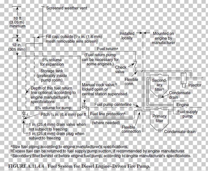
Fire Pump National Fire Protection Association Diesel Fuel Storage Tank Piping Png Clipart Angle Area Black
Is My Oil Tank Safe
Diagram Of Piping Of Two Stage Screw Heat Pump System With Flash Tank Download Scientific Diagram

Fuel Oil System Of Ships

Archnav De Piping Diagrams Print
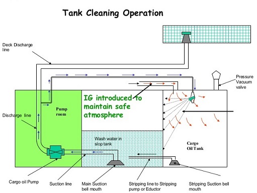
Standard Procedures For Tank Cleaning Purging And Gas Free Operation For Oil Tankers
Oil Piping For Duplex Or Paired Oil Storage Tanks
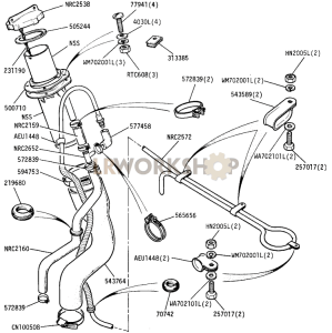
Fuel Tank Pipes Diagrams Find Land Rover Parts At Lr Workshop

Brake Oil Piping Brake Oil Tank To Brake Chamber Tbg Spec 10001 10391 Wheel Loader Komatsu Wa500 1 A Drive Shaft Differential And Wheels 777parts

Fuel Oil Systems Fuel Oil Systems Consist Of Storage Tanks Pumps Ppt Video Online Download
2
Oil Tank Fill Vent Piping Installation Inspection

Pipe Pump Sizing Preferred Utilities Mfg

Brake Oil Piping 1 3 Brake Oil Tank To Master Cylinder 12001 Wheel Loader Komatsu Wa70 1 Drive Shaft Differential And Wheels 777parts

Above Ground Stationary Utility Tanks Foremost Fuel Storage Tanks
0 Response to "37 oil tank piping diagram"
Post a Comment