37 joule thief circuit diagram
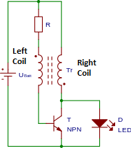
I saw [this video](https://youtu.be/xUQYMfPac0g) on wireless power transmission, which seems similar to a [Joule thief oscillator](https://en.wikipedia.org/wiki/Joule_thief) (working without any capacitors). However in contrast here the two primary coils are wound up in the same direction. How does the oscillation work here (without any capacitor), does it oscillate even without the second part of the transformator(with the LED)? From what I understand the circuit diagram looks somewhat like [t... August 27, 2018 - A useful website for electronics projects like Arduino, PIC, timers, IoT, Li-Fi, Inverters, digital clocks. Get reply for all query you ask.
September 4, 2020 -

Joule thief circuit diagram
Public circuits, schematics, and circuit simulations on CircuitLab tagged 'joule-thief'. Homemade SpeakersHomemade MobileJoule ThiefPile AaDiy ElectronicsElectronics ProjectsDiy ArtworkCircuit DiagramDiy House Projects Conectar leds a una bateria o pila con 1,5 voltios. Inversor con transistor o circuito integrado ... The joule thief flasher! July 31, 2020 - All that is required in addition ... Joule Thief circuit is a 680 pF capacitor. Apart from this, the feedback wire which is connected between ground and the wire from the ferris toroid which is also connected to a 1.5kΩ resistor and a diode, according to the circuit diagram which shows ...
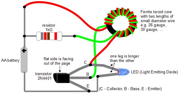
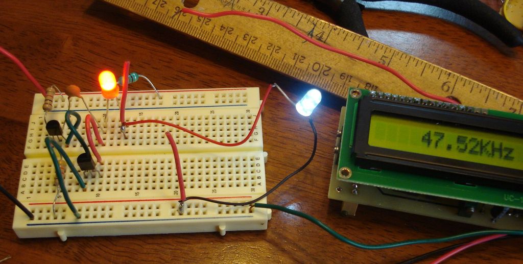
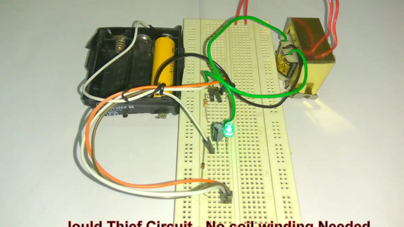
Joule thief circuit diagram. Step-by-step run through of how a Joule Thief circuit works. Includes how all the parts, the 1.5 volt AA battery, the resistor, the transistor and the ferrit... Jan 29, 2017 - Make a Joule Thief Coil Without a Ferrite Toroid: There are many different articles and videos to be found online that will teach you how to build a Joule Thief circuit and power LEDs off of dead batteries. Most of them, however, call for some form of coil made using a ring, ... Joule Thief Circuit How to Make and Circuit Explanation: A “Joule Thief” is a simple voltage booster circuit. It can increase the voltage of a power source by changing the constant low voltage signal into a series of rapid pulses at a higher voltage. You most commonly see this kind of circuit ... The waveform of an operating joule thief, showing a 30% duty cycle at approximately 40 kHz ... The circuit works by rapidly switching the transistor. Initially, current begins to flow through the resistor, secondary winding, and base-emitter junction (see diagram) which causes the transistor ...
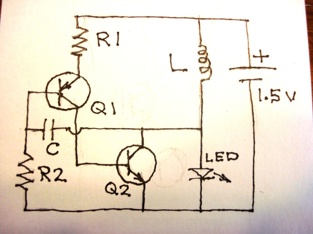
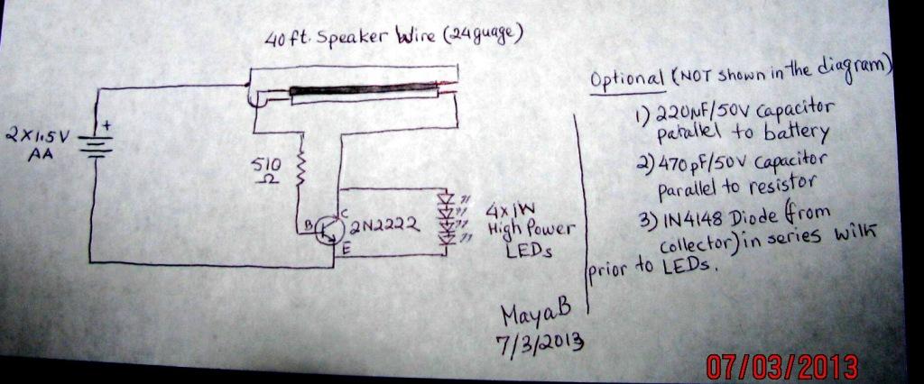
I'm working on this [diagram](http://rimstar.org/sdenergy/joule_thief/joule_thief_circuit_diagram_schematic.jpg), which I believe I have wired right and if I haven't in the [photo](https://i.imgur.com/7fh0AYv.jpg), I've tried quite a few variations. I tried the center tapped version as well. - My toroid has 12 windings. - Green from positive to collector. - White from positive over resistor to base. - LED is in the correct orientation (positive on the left, in the photo) - Emitter goes to groun... August 10, 2021 - Of course this would mean the battery getting drained pretty much earlier than a 5mm LED, but it's still economical than using a two 1.5 cells and not including a joule thief circuit. Let's try to understand the proposed circuity with the following points: If you see the circuit diagram the only ... March 2, 2015 - A “Joule Thief” is a simple voltage booster circuit. It can increase the voltage of a power source by changing the constant low voltage signal into a series of rapid pulses at a higher voltage. You most commonly see this kind of circuit used to power LEDs with a “dead” battery, but ... January 3, 2017 - The normal joule thief circuit has only two coils, but as you can see in the above circuit diagram, this one has three. That third coil and the CFL are the only additions to the regular joule thief circuit. There's also one change and that's to change the normal low power transistor for a power ...
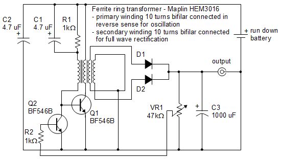
I'm on a wireless power transfer project and I "accidentally" made this circuit. At first, I needed a oscillator that makes full wave ac and tried MOSFET joule thief and realized that it's one of the blocking oscillators that makes half wave ac after trying to light an LED connected with a coil and found out that the LED turns on only at the one side of receiving coil. So I thought "what if i put two MOSFETs with two connectors(gate and drain) changed except source which is connected with ground... February 23, 2015 - A simple blocking oscillator circuit ... called a Joule thief. ... The output will be pulses of voltage that can be filtered using a diode and capacitor. As there is no regulation, the output voltage will vary with the input voltage or load. As this circuit uses a BJT, the ... November 4, 2017 - Here is the joule thief circuit used in the above photos. Transistor - The legs of the transistor can be determined by noticing that there's a flat side to the transistor case. See the diagram above. A large number of transistors have been reported to work: 2N4401, NET123AP, BC547B, 2SC2500, ... September 22, 2016 - This joule thief led or high efficiency LED with 1.5 volt driver is a tried and tested circuit built around some discrete electronics components. A common
Joule Thief Circuit Diagrams, Etc....
The Simple Joule Thief. ... Circuit diagram for Jeanna's light variation of joule thief circuit.

Pin on Renewable energy
http://www.imgur.com/HTHOxWU I'm an absolute beginner. I started a couple of days ago and refreshed basic theory, but I'm not so certain what the transistor is doing in this circuit. I think it uses the capacitor to smooth the LED charging/discharging, but maybe I am wrong. edit: http://www.maplin.co.uk/uv-banknote-checker-kit-528793#overview this is the kit I'm assembling edit2: all the above is nonsense because I have no idea what I am doing. /u/james_block pointed out that it's a [joule th...
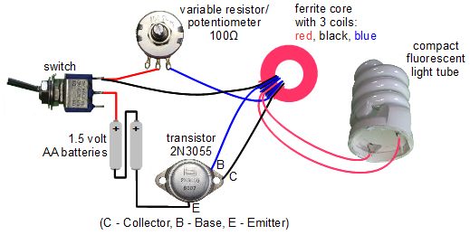
Joule thief circuit powering a compact fluorescent lightbulb
https://twitter.com/CodysLab/status/1312123574832885762 Simple and elegant. --- When the remnants of a hurricane came through my area and knocked my power out for a week, my neighbors trick was to bring his solar lights in at dusk. I think it would be a more refined to add a switch, so you could turn the light off when you wanted to sleep yet still have some juice left if you needed to go to the bathroom. But I suppose as long as you could keep a charge on your phone you could use that for ...

~: Joule Thief With Fluorescent Ballast And Relay
February 23, 2015 - This Design Idea illustrates a novel approach to the Joule Thief circuit.

Joule Thief Circuit Diagrams, Etc....
This is my first try at making the circuit. I burned out all the LEDs I had laying around. My main goal is making one that the output can be measured. I don't really care about lighting an LED. Here are the 2 toroids I made and tried, maybe the wrong toroid cores? http://i.imgur.com/aKtu8mK.jpg I have some NP 2222a transistors and a couple other ones I have also tried. I have tried this design with no luck http://rimstar.org/sdenergy/joule_thief/joule_thief_circuit_diagram_schematic.jpg And ...
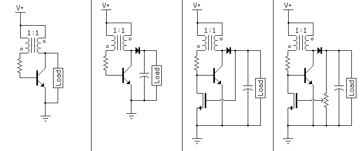
Simplifier - Voltage-Regulated Joule Thief
I'm working on a small crank-able light using a DC motor,capacitors, and LEDs with a joule thief to drain the capacitors completely when the voltage in them drops too low for the LEDs. However I want the power from the capacitors to be able to go directly to the LEDs before the capacitors drop to low voltage then switch to going through the joule thief when they hit the low voltage point to get the most efficiency. Any suggestions on how I can achieve this? I am not the best with electrical ...

Joule Thief Circuit Diagrams, Etc....
Make a SUPER Joule Thief Light! ... Circuit diagram for Jeanna's light variation of joule thief circuit.

Pin on Simple & usefull electronic circuits for many purposes
I'm working on a small crank-able light using a DC motor,capacitors, and LEDs with a joule thief to drain the capacitors completely when the voltage in them drops too low for the LEDs. However I want the power from the capacitors to be able to go directly to the LEDs before the capacitors drop to low voltage then switch to going through the joule thief when they hit the low voltage point to get the most efficiency. Any suggestions on how I can achieve this? I am not the best with electrical engi...
2011-11-29 Joule Thief pictorial diagram - RustyBolt.Info ...
Engage with the work that David Barlex and Torben Steeg are doing in D&T
QX5252F 5V Supply - EasyEDA
February 25, 2018 - I quote from Wikipedia (https://en.wikipedia.org/wiki/Joule_thief): ... This self-stroking/positive-feedback process almost instantly turns the transistor on as hard as possible (putting it in the

Joule Thief Circuit Diagrams, Etc....
July 31, 2020 - All that is required in addition ... Joule Thief circuit is a 680 pF capacitor. Apart from this, the feedback wire which is connected between ground and the wire from the ferris toroid which is also connected to a 1.5kΩ resistor and a diode, according to the circuit diagram which shows ...
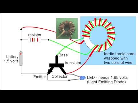
How a Joule Thief Works - YouTube
Conectar leds a una bateria o pila con 1,5 voltios. Inversor con transistor o circuito integrado ... The joule thief flasher!

free energy circuit Page 3 : Power Supply Circuits :: Next.gr
Public circuits, schematics, and circuit simulations on CircuitLab tagged 'joule-thief'. Homemade SpeakersHomemade MobileJoule ThiefPile AaDiy ElectronicsElectronics ProjectsDiy ArtworkCircuit DiagramDiy House Projects
2-Transistor Joule Thief Circuit
Joule thief - getting power from dead batteries

LED Torch Hobby Electronics, Electronics Projects, Joule ...
Transformerless Joule Thief

Simple Joule Thief Circuit Using BC547 NPN Transistor

Joule thief - getting power from dead batteries
Pin em Projects to Try

joule thief - Google Search | Joule thief, Power inverters ...

Joule Thief Circuit Diagrams, Etc....

Joule thief circuit gets overunity in 2021 | Power supply ...
Transformerless Joule Thief

Is joule thief circuit gets overunity?

Joule Thief Circuit Diagrams, Etc....

12V to 220V Inverter - Engineering Stuff-Projects,Books ...

Joule Thief Circuit Diagrams, Etc....

Making a joule thief
Joule thief circuit powering a clock
Joule Thief Circuit Diagram - DIY Electronics Projects

Joule Thief | CircuitDiagram.Org
3 Best Joule Thief Circuits | Homemade Circuit Projects

Joule Thief Circuit Diagrams, Etc....
How does the 'Joule Thief' circuit work? - Quora
Joule Thief Circuit Diagram - DIY Electronics Projects

Joule Thief Circuit Diagrams, Etc....
0 Response to "37 joule thief circuit diagram"
Post a Comment