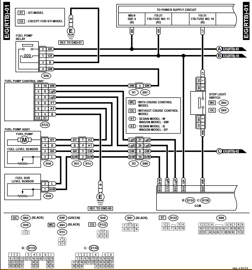
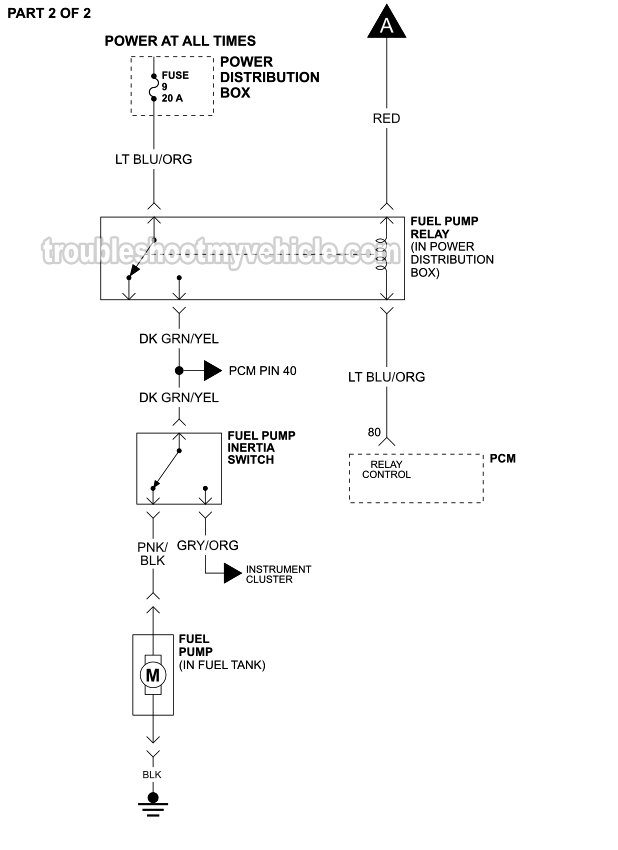
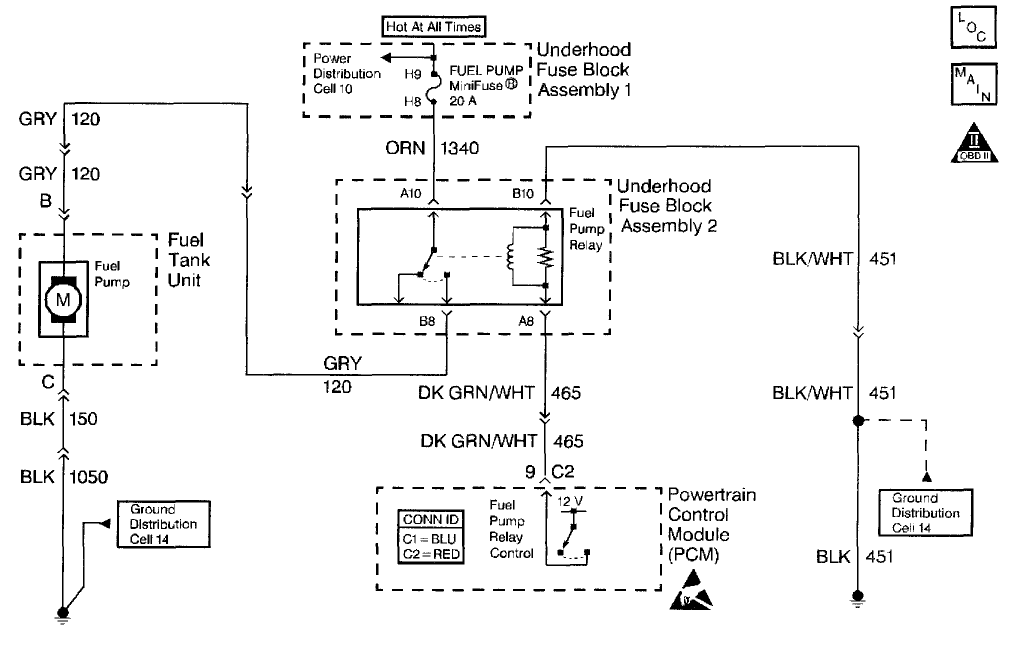
37 fuel pump connector diagram
Disconnect 12 pin connector [J2]! Clean and re-shape female sockets for round shape. Verify fuse [F1] is 5 amp and is functional! Terminal 5 to 1 or each fuse holder clip to 1 is +12VDC. Verify fuel present at carburator:! Disconnect at fuel pump and jumper board terminal 9 to 5. Verify ignition functional - … Installed new fuel pump, need wiring diagram for it. new pumps now come with a new universal so we had to re-wire it from the pump to the car, still does not run. no fuel getting from the pump, pump not. the pump is out the old pump is 3 wire conector replacement pump conector is a new gt 4 wire connector and the instructions wire color doesn't ...
7 INSPECT FUEL PUMP ASSY (See page 11–7) NG REPAIR OR REPLACE FUEL PUMP ASSY OK 8 CHECK HARNESS AND CONNECTOR(CIRCUIT OPENING RELAY – FUEL PUMP, FUEL PUMP – BODY GROUND) (a) Remove the circuit opening relay from the instrument panel J/B. (b) Disconnect the F14 fuel pump connector. (c) Measure the resistance between the wire harness side ...
Fuel pump connector diagram
Wire harness is essential to make sure your new fuel pump will operate ... the new connector, refer to the wiring diagram that's also supplied with the kit. j11 junction connector c10 malfunction indicator lamp [comb. meter] j 9 j10, junction connector ab r w-r a b- w c b-o b-o b-w b- o w w 3e 4 7if1 3d 19 3d 20 3a 15 16 9bn1 4 m 5 6bn1 w-b w-b f 8 fuel pump l l w-r l w-r w- l w- r w- r w-r w- r from center airbag w sensor assembly<17- 2> v- r … 18 Apr 2013 — There is no fuel pump operation when no start. According to GM fuel pump wiring diagram, the pump gets power from.
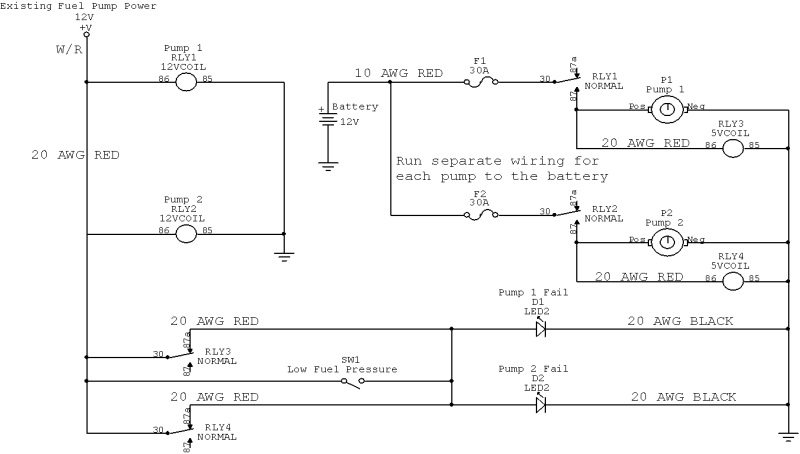
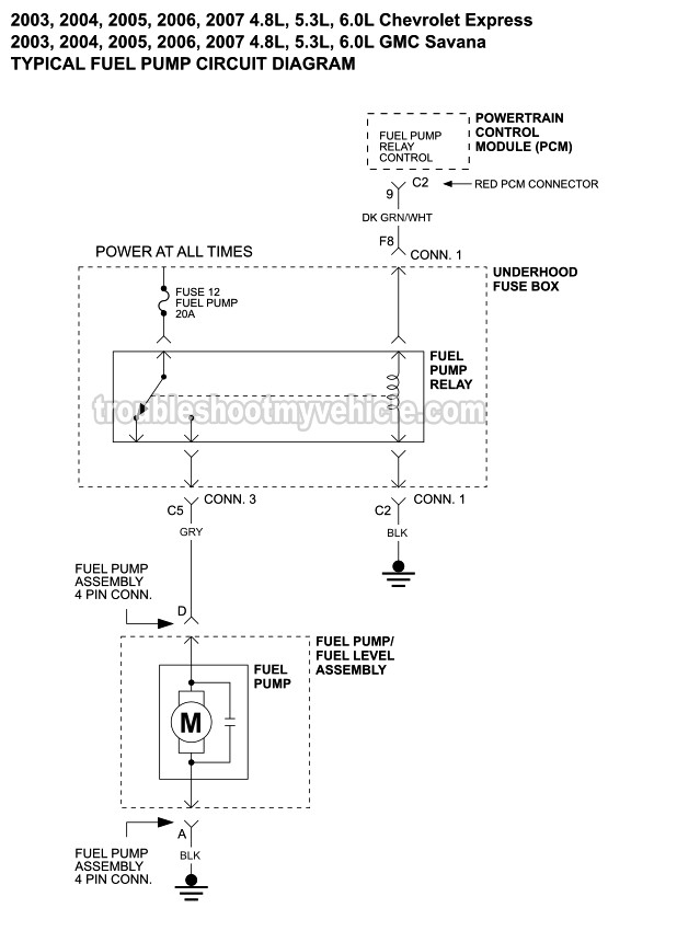
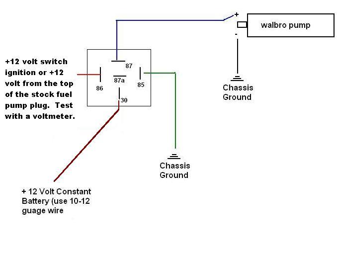
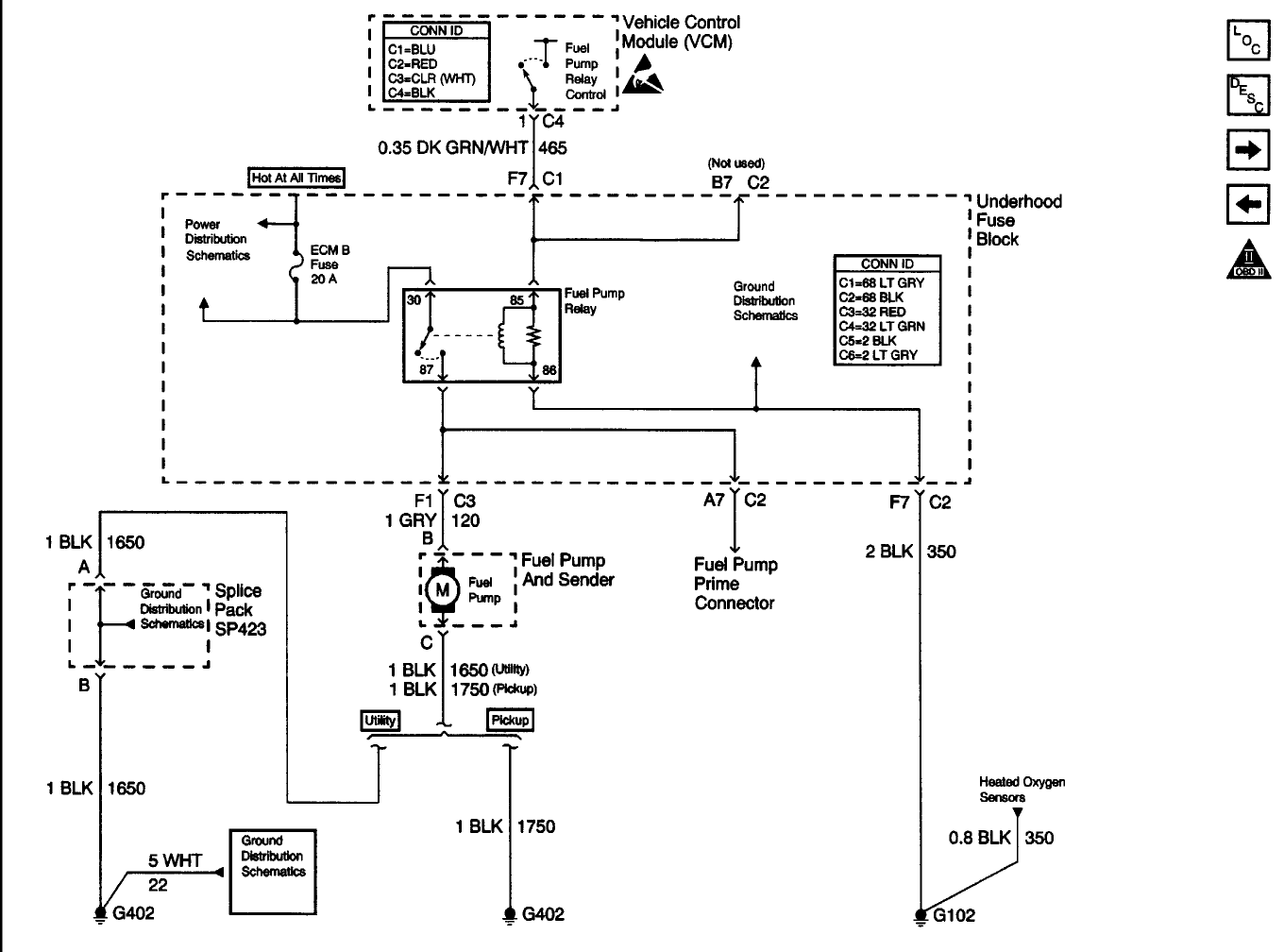
Fuel pump connector diagram. Shop for New Auto Parts at 1AAuto.com http://1aau.to/c/65/q/fuel-pumpIn this video, Brian gives a few tips on how to connect your GM fuel pump adaptor🔧 List... This project will show 2 basic wiring diagrams for electric fuel pumps. One without a warning. light one with. Some parts are optional like the inertia ... Diagram 91 Chevy Fuel Pump Full Version Hd Quality. Fuel Pump Wiring Diagram 1999 2002 4 8l 5 3l Silverado Sierra. Fuel Pump Wiring Diagram 2004 2006 2 2l Chevrolet Malibu. 2002 Yukon No Power To Fuel Pump The 1947 Present Chevrolet Gmc Truck Message Board Network. I Have A 1997 Gmc 1500 Sle And Need Wiring Diagram For Fuel Pump Would Like To ... Fuel Pump Connector Diagram Fresh Dual Fuel Pump Wiring Delphi Fuel Pump Wiring Diagram Gansoukin Me Amazon Com Airtex Electric In Tank Fuel Pumps E8023 Better Pumps Better Coverage Pioneer Avic D3 Wiring Diagram New Pioneer Avic D3 Wiring 1995 Fuel Pump Wiring Diagram Catalogue Of Schemas Airtex Fuel Pumps Water Pumps Vehicle Electronics ...
Part 1 . Page 1 of 2: 1994 Fuel Pump Circuit Tests (GM 4.3L, 5.0L, 5.7L). Fuel Pump Wiring Diagrams for 1994 Chevrolet/GMC Pickups With an Automatic or Manual Transmission. Fuel Pump Relay Wiring Diagram.Part 1 . Page 1 of 2: 1994 Fuel Pump Circuit Tests (GM 4.3L, 5.0L, 5.7L). Fuel Pump Wiring Diagrams for … Read More 15.04.2012 · This causes voltage to reach the fuel pump relay, the fuel injectors, the fuel injection computer, etc. to get power through circuit number 3. As you can see it's nothing too complicated and testing the EEC Power Relay isn't complicated either and I'll show you how in the next couple of pages. Fuel Pump. 11. 20A* Alternator Field. 12 — Not Used. 13 — Not Used. 14 — Not Used. 15 — Not Used. 16 — Not Used. 17 — Not Used. 18. 15A* Powertrain Control Module, Fuel Injectors, Fuel Pump, Mass Air Flow Sensor. 19. 10 A*. Trailer Tow Stop and Right Turn Lamp. 20. 10 A*. Trailer Tow Stop and Left Turn Lamp. 21 — Not Used. 22 ... The injector fuel control systems have a electric fuel pump, located in the fuel tank on the . During the week of October 17, , Chevrolet invited If so remove the wire from the terminal - did the pump and or engine stop?. The injector fuel control systems have a electric fuel pump, located in the fuel tank on the .
Fuel Pump Install Wiring Instructions Page 2. Instructions: If the vehicle body harness wiring does not match any of the. combinations show above, refer to the wiring identification diagram and the. vehicle service manual or equivalent to determine the correct wiring alignment. for the new GT280 Electrical connector. Fuse box diagram (location and assignment of electrical fuses and relays) for Hyundai Santa Fe (2nd/CM; 2007, 2008, 2009, 2010, 2011, 2012). 23 Nov 2015 — need color code diagram to install Delphi fuel pump in a 2001 rodeo 3.2 fwd. all wires match except the one that says that black/white goes ... Nice Ford Fuel Pump Relay Wiring Diagram Graphic Graphic - bookingritzcarlton.info. Credit Image = http:// www.justanswer.com . Are You Ready For Professional ...
Cadillac Escalade Fuel Pump Wiring Diagram Fuel Pump Connector with regard to 2003 Trailblazer Fuel Pump Wiring Diagram by admin From the thousand photos on the web with regards to 2003 Trailblazer Fuel Pump Wiring Diagram, we all choices the very best series using ideal quality exclusively for you, and now this photos is considered one of pictures collections in your greatest graphics gallery ...
It doesn’t really matter which way round the hoses go on a two hose system as they just feed to either side of the fuel rail, however, the manual does have a diagram showing fuel flow should go from the lower fuel plate connection to the right hand side of the fuel rail and the top fuel plate connection receives the fuel return hose from the left hand side of the fuel rail (looking forward ...
See Figure 3 for diagram of vacuum ports. Vacuum Port Side View ... Fuel pressure should be checked on the inlet fuel line before initial start up during the fuel pump prime. We recommend Earl’s Part Number 100187ERL (0-100 psi Liquid filled gauge) & AT100199ERL (-6AN Gauge Adapter) to check fuel pressure. Fuel Fitting Overviews Figure 4 . 5 Locate a position for the oxygen sensor as close ...
18 Apr 2013 — There is no fuel pump operation when no start. According to GM fuel pump wiring diagram, the pump gets power from.
j11 junction connector c10 malfunction indicator lamp [comb. meter] j 9 j10, junction connector ab r w-r a b- w c b-o b-o b-w b- o w w 3e 4 7if1 3d 19 3d 20 3a 15 16 9bn1 4 m 5 6bn1 w-b w-b f 8 fuel pump l l w-r l w-r w- l w- r w- r w-r w- r from center airbag w sensor assembly<17- 2> v- r …
Wire harness is essential to make sure your new fuel pump will operate ... the new connector, refer to the wiring diagram that's also supplied with the kit.










0 Response to "37 fuel pump connector diagram"
Post a Comment