36 si c phase diagram
192 / Phase Diagrams—Understanding the Basics. A hypothetical ternary phase space diagram made up of metals . A, B, and . C. is shown in Fig. 10.2. This diagram contains two binary eutectics on the two visible faces of the diagram, and a third binary eutectic between ele-ments . B. and . C. hidden on the back of the plot. Because it is ... 計算熱力学はいわば"物性推算法"の一つであり、用いる熱力学データベースも、もっとも良さそうな"推算値"で構成されています。. これらは様々な情報に基づき、細心の注意を払って推定されたものですが、間違いや問題はあり得ます。. 従って、それ ...
Abstract. The two most recently published [1 to 3] phase diagrams for the Si-C system show somewhat deviating results. They were combined by [4], giving the diagram shown in Fig. 1. The only condensed phases that occur in this phase diagram are silicon, silicon carbide (SiC), and graphite [4]. See also [5, 6].
Si c phase diagram
Phase Diagrams • Indicate phases as function of T, Co, and P. • For this course:-binary systems: just 2 components.-independent variables: T and Co (P = 1 atm is almost always used). • Phase Diagram for Cu-Ni system Adapted from Fig. 9.3(a), Callister 7e. (Fig. 9.3(a) is adapted from Phase Diagrams of Binary Nickel Alloys , P. Nash In the equation (4), the total energy of phase mixture of solid solutions for −Si Ge is given by () ( )1 Si Ge. mix = − + E x x E xE (5) In the equation (5), ESi and EGe are the total energy per atom of Si and Ge calculated with the equation (1). 2.4. Phase diagram at low temperatures In this work, we have investigated the phase diagram at Si 2 O 8 T1 T2 T3 An 67 55% An 87 An 95 45% Ab An An 32 Binary Solid Solution Phase Diagram Temp. %Melt Comp. Melt %Solid Comp. solid T 1 100 An67 0 An95 T 2 55 An53 45 An87 T 3 0 An32 100 An67 An 53 Fractional crystallization of composition M An 95 An 0 Equilibrium Crystallization of M
Si c phase diagram. 2.1. Al-Mg-Si PHASE DIAGRAM The Al-Mg-Si phase diagram can be used for the analysis of many wrought alloys of 6XXX series and casting alloys of the 356.0 type, provided the concentration of iron impurity is low (Table 2.1). This diagram is also the basic diagram for casting alloys of the 512.0 type that are considered in Chapter 4. Here too, understanding the phase diagram better is a route towards improving the properties (i.c. the silicon content) of electrical steels. The standard phase diagram for Fe-Si is the one by Kubaschewski (1982). In the iron-rich region, the dominant phases are a-Fe (0 at.% Si), DO3 (a1, 25 at.% Si) and B20 (e, 50 at.% For the system Ti Si C phase diagrams at 1373 K and at 1523 K were determined. For that purpose, several alloys and diffusion couples were equilibrated and analysed by EPMA (electron probe ... The Ti-Si-N-O quaternary phase diagram • Entire phase diagram can be calculated by taking into account all possible combinations of reactions and products • 4 ternary diagrams of Ti-Si-N, Ti-N-O, Ti-Si-O and Si-N-O were evaluated • additional quaternary tie lines from TiN to SiO 2 and Si 2N 2O A.S.Bhansali, et al., J.Appl.Phys. 68(3 ...
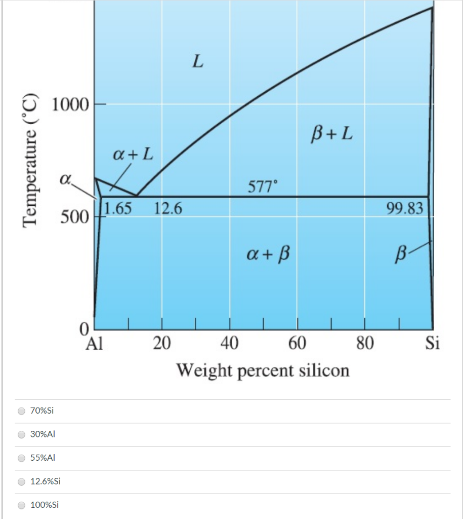
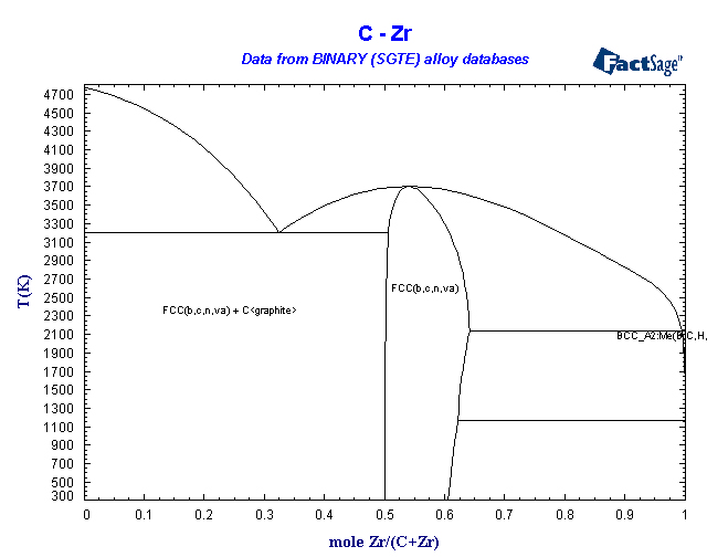
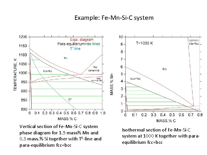
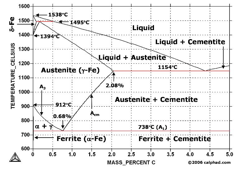
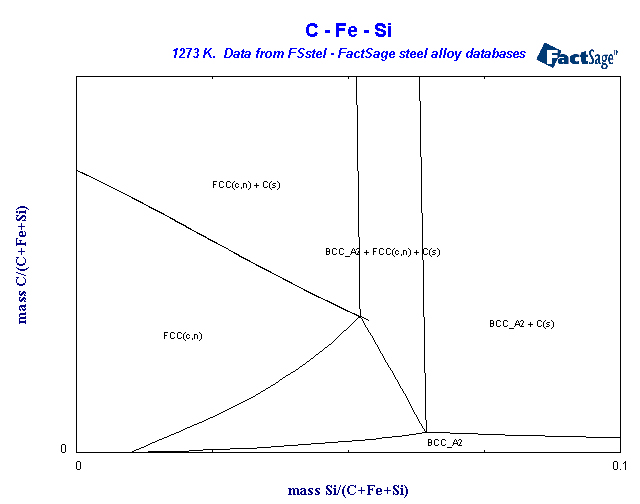
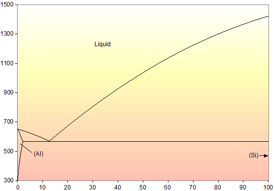
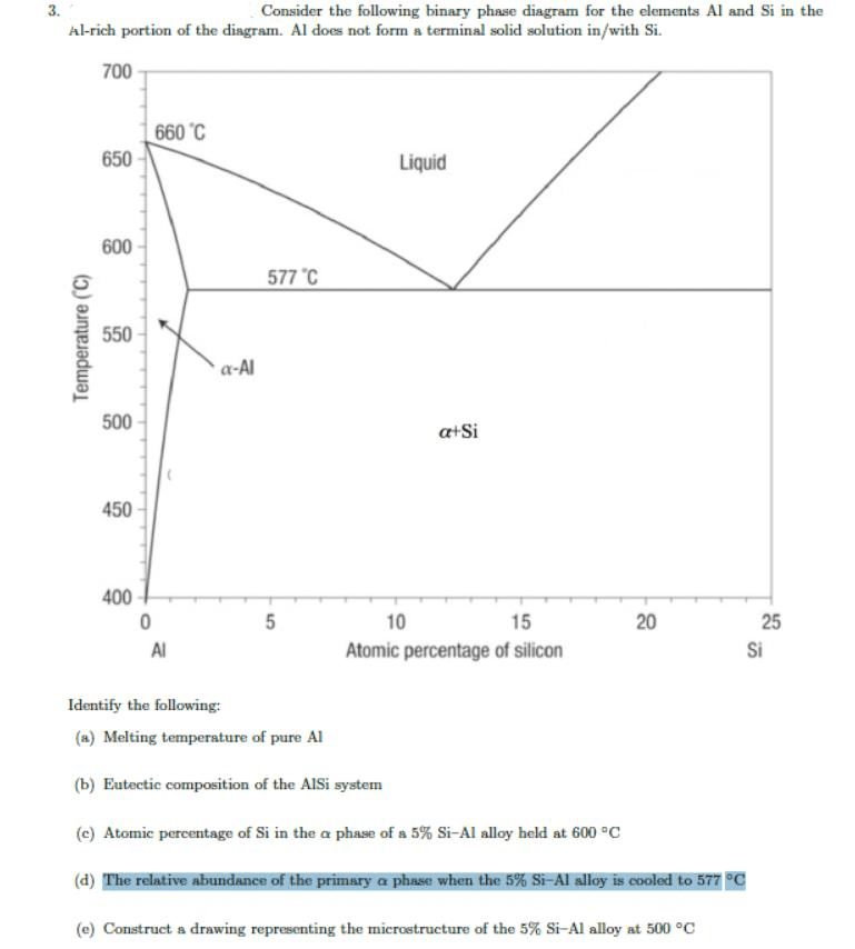
The Si-C-O predominance diagram, in conjunction with a free-energy minimum of the gas phase, has been used to explain several observations in the reactions of SiC and/or carbon with SiO2. the phase diagram from experimental thermodynamic data. The main purpose of the present study has been to do computer calculations of isothermal sections of the Fe-C-Si stable and metastable phase diagrams by using thermodynamic data from the three contributory binary systems. The Al-Si phase diagram is a straightforward, classic example of a eutectic system where each element has little, if any solubility in the other. Aluminum melts at 660.452 °C while silicon melts at 1414 °C. The diagram, from Murray and McAlister (Vol. 8, Metals Handbook, 8th ed., 1973, p. 263), shows the eutectic at 12.6 wt. % Si and 577 °C. and 12. As seen the liquidus surface falls steeply from the very high temperatures in the C-rich part ofthe diagram. Graphite is the primary phase above -25a% C at the Mn-Cbaseline, and this region extends up the C/SiC coexistence line at -13a% C. SiC is present from -21a% Si and
FactSage 8.1 - List of Stored Phase Diagrams (7811) FACT Databases. FToxid FACT oxide data (501) FTsalt salt data (351) FTmisc sulfide, alloy, micellaneous data (39) ... SpMCBN Spencer Group M-C-N-B-Si alloys (837) Click on a system to display the phase diagram. (NH4)2SO4-H2O FTfrtz (NH4)2SO4-H2O_with_gas FTfrtz Si Mn W Mo Review Fe-C phase diagram • 2 important points-Eutectoid (B): γ⇒α+Fe 3C-Eutectic (A): L ⇒γ+Fe 3C Fe 3 C (cementite) 1600 1400 1200 1000 800 600 400 0 12 3 4 5 66.7 L γ (austenite) γ+L In this Letter we present a calculation of the temperature-pressure phase diagram of Si in a range of pressures covering from − 5 to 20 GPa and temperatures up to the melting point. The phase boundaries and triple points between the diamond, liquid, β-Sn, and Si 34 clathrate phases are reported. We have employed efficient simulation techniques to calculate free energies and to numerically ... Phase Diagram Resources from ASM International. Alloy phase diagrams and crystal structure data are used by metallurgists, materials engineers, and materials scientists to develop new alloys for specific applications; fabricate these alloys into useful configurations; design and control heat treatment procedures for alloys that will produce the required mechanical, physical, and chemical ...
Solved In The Al Si Phase Diagram The Composition Of Liquid Chegg Com
The Si-C binary phase diagram. The main features of the Si-C binary phase diagram were described long ago, with SiC being the only stable compound of the diagram (Fig. 5.1). Some discrepancies can be found in the literature, especially in the determination of the invariant transformations and the description of the SiC liquidus.
1
Define the following: (a) liquidus, (b) solidus, (c) solvus, (d) fractional crystallization (e) solid solution, (f) incongruently melting compound. Draw examples of phase diagrams that show the following - be sure to label everything. a phase diagram that has an intermediate compound that melts incongruently.
Eprints Iisc Ac In
Title Phase Diagram and Thermochemistry of the Al-Mg-Si System Publication Z. Metallkd. Language English Authors Lüdecke D., Aachen RWTH University, Lehrstuhl für Metallurgie der Kernbrennstoffe und Theoretische Hüttenkunde, Aachen, Germany Original diagram Al-Mg-Si isothermal section at 427 °C

Review Chemical Compatibility Of Sic Sic Composites With The Gfr Environment C Cabet Laboratoire Of Non Aqueous Corrosion Cea Saclay France Ppt Download
The simplest phase diagrams are pressure-temperature diagrams of a single simple substance, such as water.The axes correspond to the pressure and temperature.The phase diagram shows, in pressure-temperature space, the lines of equilibrium or phase boundaries between the three phases of solid, liquid, and gas.. The curves on the phase diagram show the points where the free energy (and other ...

First Principles Phase Diagram Calculations For The Wurtzite Structure Quasibinary Systems Sic Aln Sic Gan And Sic Inn Journal Of Applied Physics Vol 110 No 2
Understanding Phase Diagrams - V.B. John . Ternary phase diagram books by D.R.F. West - there are several . Ternary grid . Space diagram . C A B . Space diagram . Usually have elements at the corners as the constituents,
Osti Gov
The Al-Si Phase Diagram The binary Al-Si phase diagram was initially studied by Fraenkel of Germany in 1908. It is a relatively simple binary diagram where there is very little solubility at room temperature for Si in Al and for Al in Si. Thus, the terminal solid solutions are nearly pure Al and Si under equilibrium conditions.

Scielo Brasil Liquid Phase Sintered Sic Processing And Transformation Controlled Microstructure Tailoring Liquid Phase Sintered Sic Processing And Transformation Controlled Microstructure Tailoring
The phase diagram of Ti-Si-C at 1473 K from Bruckl. z homogeneity region for TisSi3, 4 from 61 at.% up to 63.8 at.% Ti, whereas it is reported by Bruckl as a line compound without any homogeneity region. The extension of this region on addition of carbon seems unrealistic in comparison with e.g. MosSi3 .5 ...
Triceceramics Com
Metall., 12, 78-81 (1972) in Russian. (Crys Structure, Equi Diagram; Experimental) Google Scholar. Indicates key paper 73Vol: F.W. Voltmer and F.A. Padovani, "The Carbon-Silicon Phase Diagram for Dilute Carbon Concentration and the Influence of Carbon on Czochralski Growth of Silicon", Semicond.
Si X Phase Diagrams
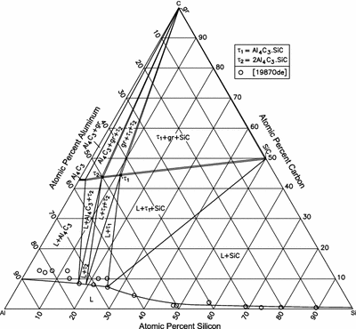
The phase diagram of the ternary system Al-C-Si was optimised using experimental data from the literature. The binary Al-C and Al-Si systems were taken from the literature. The Si-C system was also optimised using the least square method. The calculated sections agree very well with the experimental data.
Binary Sgte Alloy Phase Diagrams
In the Si/C phase diagram, the only stable phases at P = 1 atm are the numerous polytypes of the simplest 1:1 stoichiometry, SiC. However, many metastable yet likely to be kinetically persistent phases can be found for almost any composition. Given the instability of simple graphite-type structures …

A The Calculated Isothermal Section Of The Al Si C Phase Diagram At Download Scientific Diagram
dissolved in the liquid phase. At the equilibrium temperature of 680 °C, the liquid phase only contains 2.0 wt% SiO 2. When the liquidus tem-perature increased to 900 and 1100 °C, 3.8 and 7.1 wt% SiO 2 were dissolved in the liquid, respectively. From the perspective of phase diagram, the results indicate that SiO 2 has a large primary phase ...
Ir Nsfc Gov Cn
Si 2 O 8 T1 T2 T3 An 67 55% An 87 An 95 45% Ab An An 32 Binary Solid Solution Phase Diagram Temp. %Melt Comp. Melt %Solid Comp. solid T 1 100 An67 0 An95 T 2 55 An53 45 An87 T 3 0 An32 100 An67 An 53 Fractional crystallization of composition M An 95 An 0 Equilibrium Crystallization of M
Jurnal Unej Ac Id
In the equation (4), the total energy of phase mixture of solid solutions for −Si Ge is given by () ( )1 Si Ge. mix = − + E x x E xE (5) In the equation (5), ESi and EGe are the total energy per atom of Si and Ge calculated with the equation (1). 2.4. Phase diagram at low temperatures In this work, we have investigated the phase diagram at

Phase Relations In Si Al Y O C Systems
Phase Diagrams • Indicate phases as function of T, Co, and P. • For this course:-binary systems: just 2 components.-independent variables: T and Co (P = 1 atm is almost always used). • Phase Diagram for Cu-Ni system Adapted from Fig. 9.3(a), Callister 7e. (Fig. 9.3(a) is adapted from Phase Diagrams of Binary Nickel Alloys , P. Nash
The Role Of Phase Transformation Kinetics In Phase

Phase Diagram Of The System Si C For Pressures Above 108 Atm 10 By Download Scientific Diagram
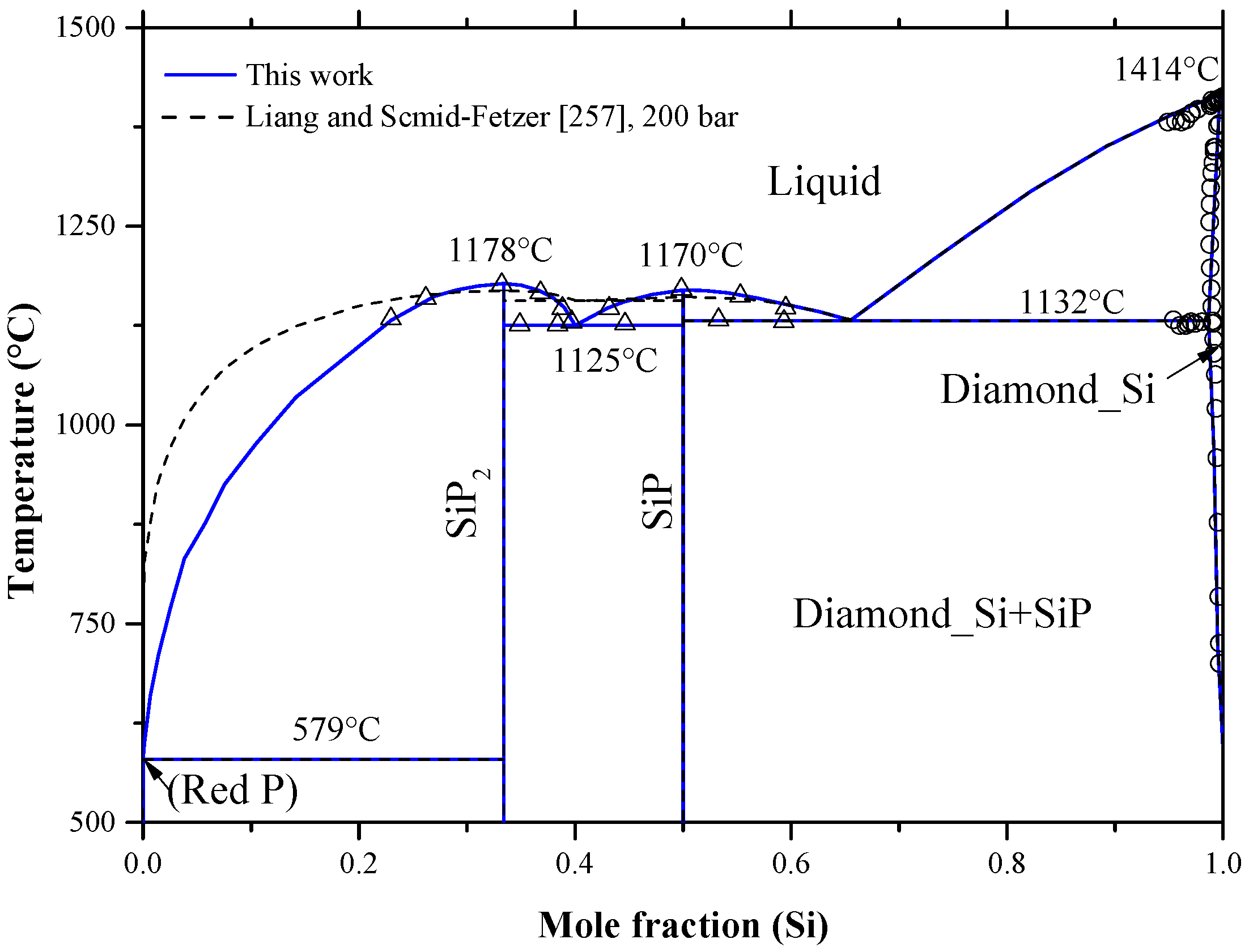
Materials Free Full Text Binary Phase Diagrams And Thermodynamic Properties Of Silicon And Essential Doping Elements Al As B Bi Ga In N P Sb And Tl Html

Ni Si C Phase Diagram At 1 800 K Redrawn From 45 Download Scientific Diagram

Chapter 3 Bulk Growth Of Silicon Carbide Fundamentals Of Silicon Carbide Technology Growth Characterization Devices And Applications Book
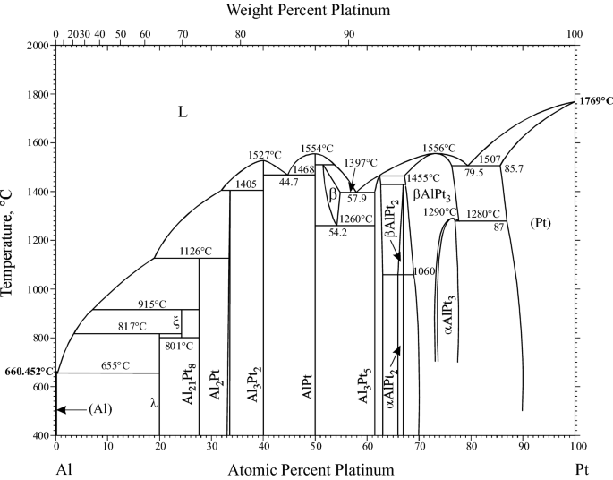
Supplemental Literature Review Of Binary Phase Diagrams Al Pt As U C Li C Mg Cd Nd Co Ta Fe Re Ga Y La Ni O V P Si And Re Zr Springerlink
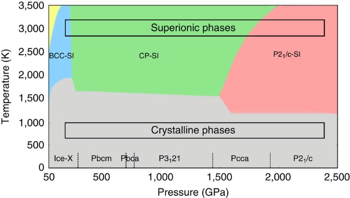
The Phase Diagram Of High Pressure Superionic Ice Nature Communications

Applications
Phase Diagram Metallurgy For Dummies
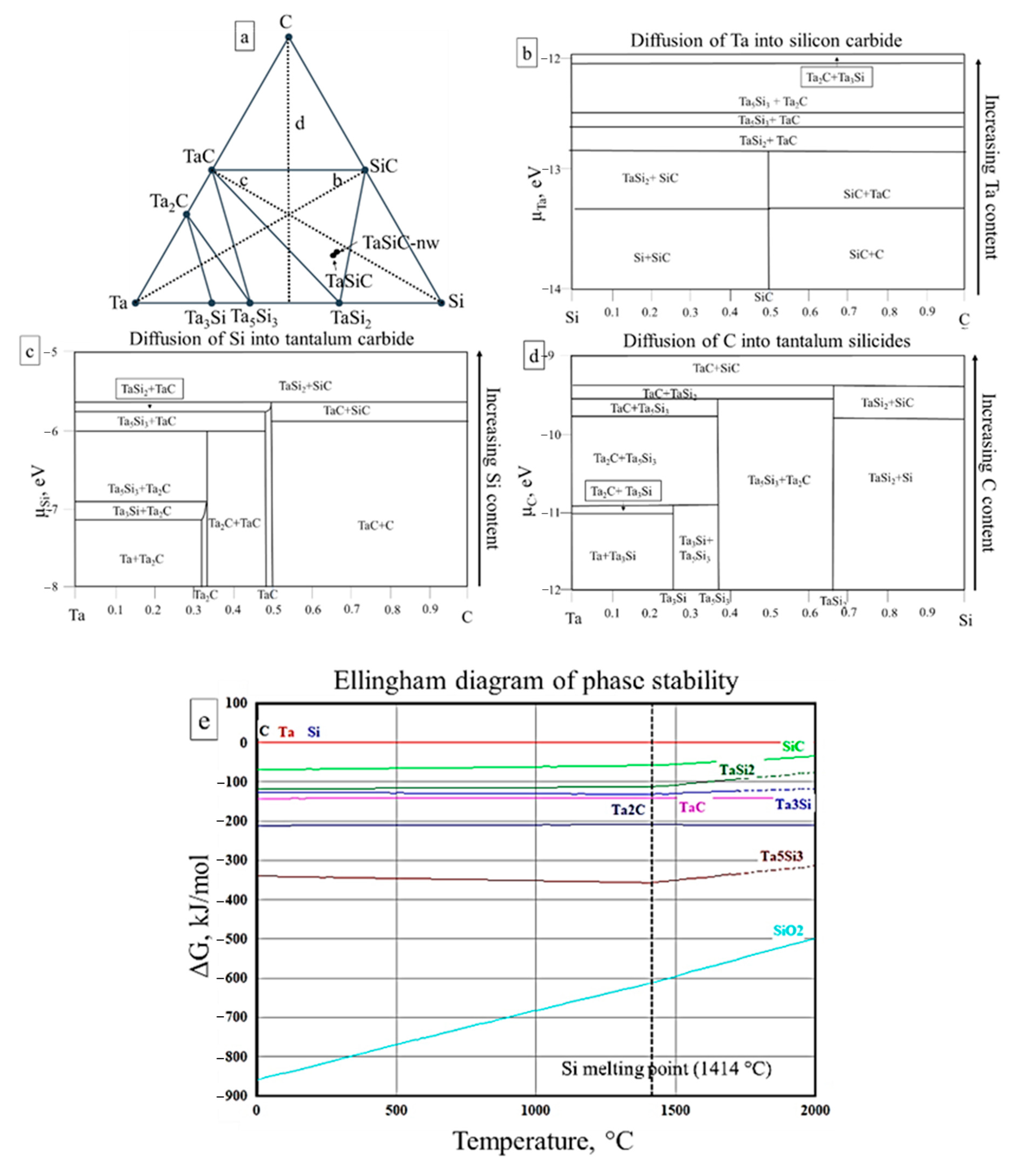
Materials Free Full Text Effect Of In Situ Grown Sic Nanowires On The Pressureless Sintering Of Heterophase Ceramics Tasi2 Tac Sic Html
Fsstel Factsage Steel Alloy Phase Diagrams

Gas Transport Mechanisms And The Behaviour Of Impurities In The Acheson Furnace For The Production Of Silicon Carbide Sciencedirect
Phase Diagram For Al Si

Consider The Al Si Phase Diagram In The Figure Below 1500 B L Temperature C 500 1 65 12 6 Homeworklib
Al C Si Aluminum Carbon Silicon Springerlink

File Fe Graphite Phase Diagram Greek Svg Wikimedia Commons
Oneclass 3 Consider The Following Binary Phase Diagram For The Elements Al And Si In The Al Rich Po
Trace Tennessee Edu
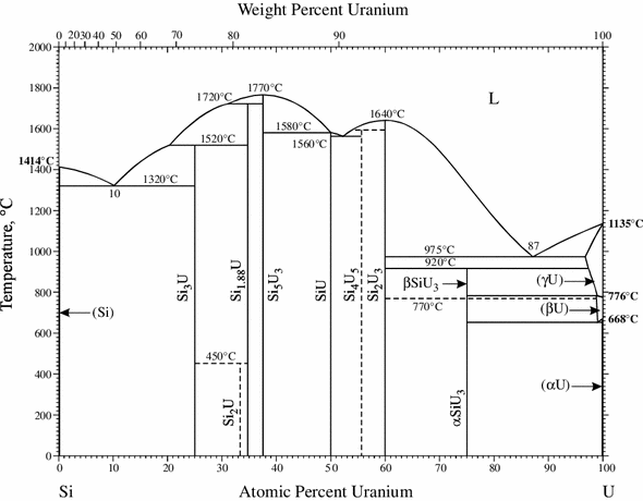
Si U Silicon Uranium Springerlink

Pauling File
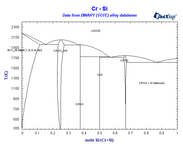
Binary Sgte Alloy Phase Diagrams

Al C Phase Diagram And Database Gedb For Factsage
0 Response to "36 si c phase diagram"
Post a Comment