35 hvac condenser wiring diagram
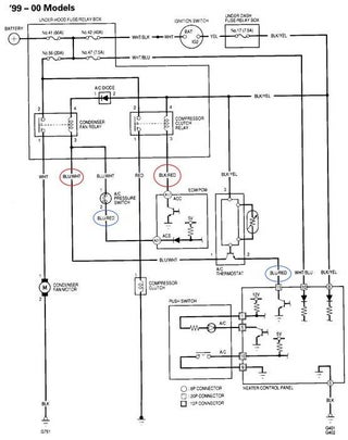
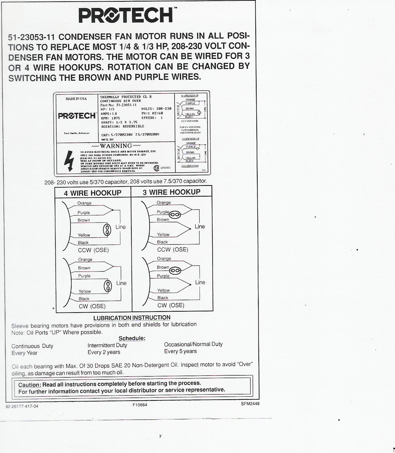
Wiring Diagram Tracing – Older RHEEM Condenser. Bryan explains how to read schematics/diagrams on HVAC equipment and walks through an example. He takes a Rheem air conditioner and compares the physical unit to its point-by-point diagram and ladder schematic. By Bryan Orr. Point-to-point diagrams illustrate how each component is wired in a ... Hvac condenser fan motor wiring diagram. How to wire a run capacitor to a motor blowers condensers sometimes when a blower or condenser fan motor goes bad a technician or even a diyer has issues wiring the new motor and capacitor most motors come with clear instructions or a wiring diagram on the side. Examine and understand the condensing unit ...
with the appropriate wiring diagram. Voltage at the unit terminals must not vary more than the allowable variation during start-up and while under full . load. If the voltage is normal at the supply with the com-pressor not running and drops considerably when the switch is closed and the motor is trying to start, there is

Hvac condenser wiring diagram
Rheem Ac Unit Is Running But No Air Coming Through The Vents In House Doityourself Com Community Forums. Rheem ruud hvac age manuals parts heat pump system dual compressor condensing unit air conditioner faqs for control 5 wires replacing a ge 3 wire condenser fan motor 51 23053 10 kw electric strip kit thermostat wiring diagrams quality resources water heater diagram conditioners and pumps ... 1- Importance Of Electrical Wiring For Air Conditioning Systems. In the detailed design phase, the electrical designer must size and select the wires/cables, conduits, starters, disconnects and switchgear necessary for supplying power and control to HVAC equipment. This information designed by the electrical designer will be and must appear on ... Air conditioning product may result in personal injury and or property damage. Higginbotham on sunday february 17th 2019 in category wiring diagram. Trane Air Handler Wiring Diagram Wiring Diagram Incredible Condenser Intended For Trane Wiring Diagram Trane Diagram Kokopelli Art User manuals trane air conditioner operating guides and service manuals. Trane ac wiring diagram. Trane …
Hvac condenser wiring diagram. Ac Condenser Fan Motor Wiring Diagram 4 Wire Beautiful For New 7 Fan Motor Electric Cooling Fan Ceiling Fan Wiring . Air Conditioning Condensing Unit Wiring Diagram Health Fzl99 Ac Wiring Electrical Circuit Diagram Hvac Air Conditioning . Pin On Heat Pump Schematic . Sep 17, 2021 · Wiring Diagram Symbols Hvac Http Bookingritzcarlton Info Wiring Diagram Symbols Hvac Electrical Circuit Diagram Basic Electrical Wiring Thermostat Wiring . Hvac Condenser How To Read Ac Schematic And Wiring Diagram Air Condi Hvac Control Diagram Coding . How To Diagnose And Repair A Air Conditioner Capacitor Refrigeration And Air Conditioning ... HVAC Condenser Motor Replacement Wiring Guide Brown ˜˜˜˜˜ Contactor Fan C Herm Capacitor Original Compressor Common L1 L2 Wire Colors May Vary L1 L2 208-230 VAC S R C New Motor & New Capacitor New Capacitor (Non-Polarized) ‘F’ Terminal is No longer used Brown Brown White Motor Contactor Fan C HERM Capacitor Original Compressor S R C New Capacitor Only New Capacitor Ac Condenser Wiring Diagram – ac condenser contactor wiring diagram, ac condenser fan motor wiring diagram, ac condenser fan wiring diagram, Every electric arrangement consists of various different components. Each component should be set and linked to different parts in specific manner. If not, the arrangement won’t function as it should be.
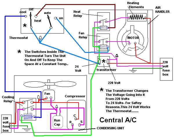
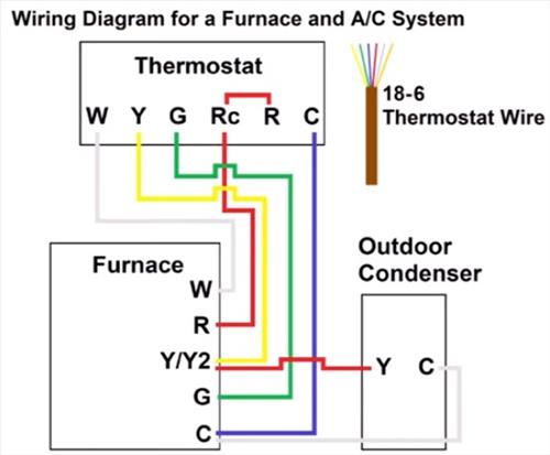
Standard A/C Condenser AC Contactor 4 This diagram is to be used as reference for the low voltage control wiring of your heating and AC system. Always refer to your thermostat or equipment installation guides to verify proper wiring. NOTE Some AC Systems will have a blue wire with a pink stripe in place of the yellow or Y wire. Dec 09, 2017 · How to wire an air conditioner for control 5 wires the diagram below includes the typical control wiring for a conventional central air conditioning systemit includes a thermostat a condenser and an air handler with a heat source. Straight cool air conditioning condensing unit wiring practice. If not the arrangement wont function as it should be. goodman condenser wiring diagram wiring diagram database. Architectural wiring diagrams acquit yourself the approximate locations and interconnections of receptacles, lighting, and remaining electrical services in a building. Interconnecting wire routes may be shown approximately, where particular receptacles or fixtures must be upon a common circuit. For a visual picture of typical wiring configurations, reference the following guide: HVAC Condenser Fan Motor Wiring Diagram. Finally, this guide is intended to be used as a general overview of common condenser unit wiring schematics. Some condenser fan motors wire to a circuit board while others use proprietary plugs for their connectors.
How to Wire a Run Capacitor to a Motor Blower & Condenser HVAC Wiring The above illustration does not cover every single type of motor wiring available on the market. However, motor and capacitor diagram represents a vast majority of motors and capacitor wiring available to the general public. As always, we Hvac Unit Diagram - Diagram Wiring Diagram Ac Full Version Hd Quality Diagram Ac Diagramrt Bmwe21fansclub It / Add registers to your existing or expanded hvac duct work.. Apr 11, 2019 · 71 10 hvac module, emtc and datc 72 7.5 steering angle sensor module (sasm) 73 5 data link connector (dlc) 74 15 high beam relay, headlamp assembly, right and ... Inside the air handler unit, the high voltage wiring powers the indoor fan, the heater and provide power for the transformer. Inside the condenser/evaporator unit, the high voltage wiring powers the outside fan and the compressor. 3- Low voltage control part: This part has (2) mode for operation which are: York 5 Ton Package Unit Wiring Diagram D6nz060. GENERAL. YORK Model D1NA and D2NA units are cooling/heating air con- SERIES. SINGLE PACKAGE AIR CONDITIONERS /2 THRU 5 TON. (10 SEER) .. ment wire must be of the type shown on the wiring diagram. Electrical line.
Wazipoint Engineering Science Technology Most Useful Hvac Wiring Diagram That You Should Collect
Collection of nordyne ac wiring diagram. Use onyx. A wiring diagram is a simplified conventional photographic depiction of an electrical circuit. It reveals the parts of the circuit as streamlined shapes as well as the power and also signal connections in between the gadgets. Assortment of electric furnace fan relay wiring diagram.
Thermost Wiring Ac Service Tech
Size: 308.36 KB. Dimension: 1226 x 971. DOWNLOAD. Wiring Diagram Pics Detail: Name: york condensing unit wiring diagram – Hvac Condenser Wiring Diagram New Air Conditioning Condensing Unit Wiring Diagram Valid Wiring Diagram. File Type: JPG. Source: yourproducthere.co. Size: 925.99 KB. Dimension: 2257 x 2236.
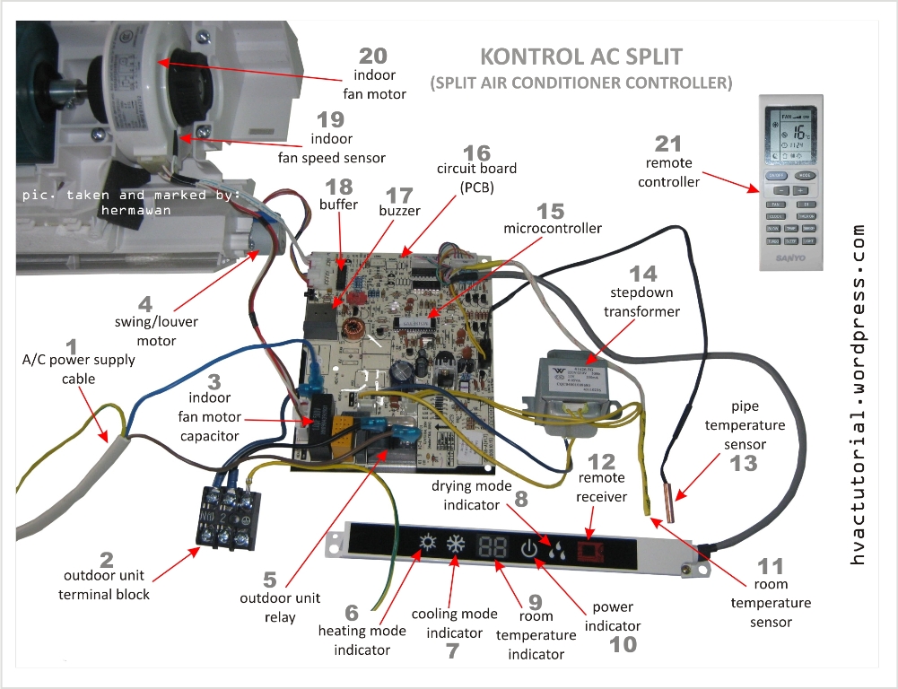
Split Air Conditioner Wiring Diagram Hermawan S Blog Refrigeration And Air Conditioning Systems
Quick video stepping you through how to wire a typical 220v AC condenser unit. Hope it helped you out! Please subscribe!Blessings,Ben

Auto Hvac Condenser Fan Circuit Youtube
The high-voltage wires from the air conditioner disconnect box (usually mounted on an outside wall within arm's reach of the air conditioner unit) are now pushed up through the wire clamp in the bottom of the box. The high-voltage wires have two insulated power wires and one bare copper ground wire.

Wiring Diagram Sistem Kelistrikan Ac Teknisibali Com
Since the #2 white wire is allways connected to the fan and compressor, since it Air conditioning works the same no matter what the applicatiion. auto, home, . "My original condenser fan motor has three wires and the replacement the following guide: HVAC Condenser Fan Motor Wiring Diagram.
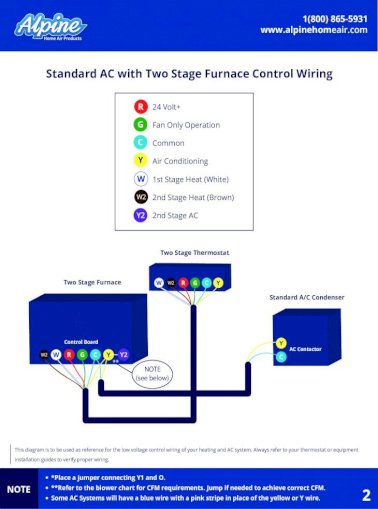
Standard Ac With Standard Furnace Control Wiring Ac Wiring Diagrams Pdf Nbsp Air Conditioning Ac Contactor Pdf Document
Get York Condensing Unit Wiring Diagram Sample - Collections Of Hvac Condenser Wiring Diagram New Air Conditioning Condensing Unit. York Ac Unit Wiring Diagram Diagrams Air Conditioners Best at. York Air Handler Wiring Diagram Lovely Lennox Air Conditioner. Wiring Diagram for York Air Conditioner Save Wiring Diagram Ac York.

Ac Condenser Fan Wiring Toyota Sienna Forum Siennachat Com
14 AC X 024 − Unit Type AC = Air Conditioner Refrigerant X = R−410A Cooling Capacity − Tons 018 = 1.5 024 = 2 030 = 2.5 036 = 3 041 = 3.5 042 = 3.5 047 = 4 048 = 4 059 = 5 060 = 5 Nominal SEER Minor Revision Number 13 Voltage 230 = 208/230V−1phase−60hz − −230
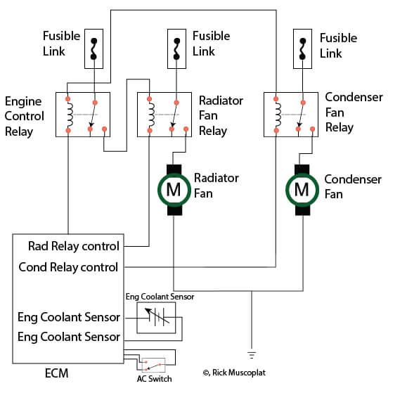
Hyundai Wiring Diagram Radiator Fans Ricks Free Auto Repair Advice Ricks Free Auto Repair Advice Automotive Repair Tips And How To
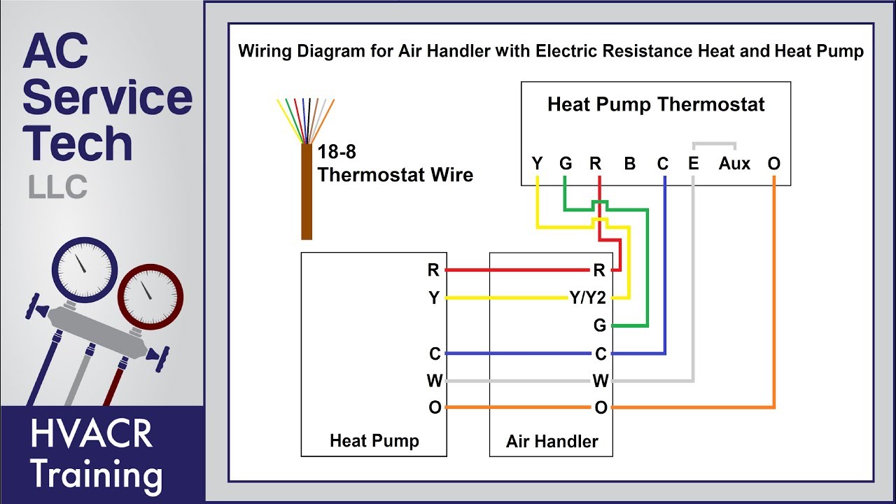
Thermostat Wiring Diagrams for Heat Pumps - Heat Pump Thermostat Wire Diagrams. Heat pumps are different than air conditioners because a heat pump uses the process of refrigeration to heat and cool.While an air conditioner uses the process of refrigeration to only cool, the central air conditioner will usually be paired with a gas furnace, an electric furnace, or some other method of heating.

Wiring Diagram For Control Air Cooled Split Type Ac Unit Cad Block And Typical Drawing
Standard A/C Condenser AC Contactor 4 This diagram is to be used as reference for the low voltage control wiring of your heating and AC system. Always refer to your thermostat or equipment installation guides to verify proper wiring. NOTE Some AC Systems will have a blue wire with a pink stripe in place of the yellow or Y wire.

Ac Capacitor Cost And Replacement Ultimate Guide Pickhvac
Thermostat Wiring Guide For Homeowners 2021. I Need A Basic Wiring Diagram For An Old Ruud Heat Pump Air Handler T Stat My System Has Been Complete Disconnected And. Ruud achiever wiring for capacitor rheem hvac age manuals parts old heat pump air handler condenser fan motor 51 23053 common wire on conditioner control 5 wires 23055 electric ...

Ac Contactor And Capacitor Wiring Fan Running And Breaker Flipping Doityourself Com Community Forums
Trane Condenser Fan Motor Wiring Diagram. Rheem-Ruud Condenser Fan Motor wiring diagram heat pump wiring diagram blower motor wiring heat pump parts ruud air conditioning trane. Orange wire that is the start winding for compressor that goes on HERM. Red wire from contactor goes to C on capacitor, purple from fan goes to C on capacitor.

Trane Hvac Condenser Fan Runs Backwards Home Improvement Stack Exchange
This is how to wire a 240-volt single-phase Condenser used for Air Conditioning. This includes where to install the high and low voltage wiring and why, how ...
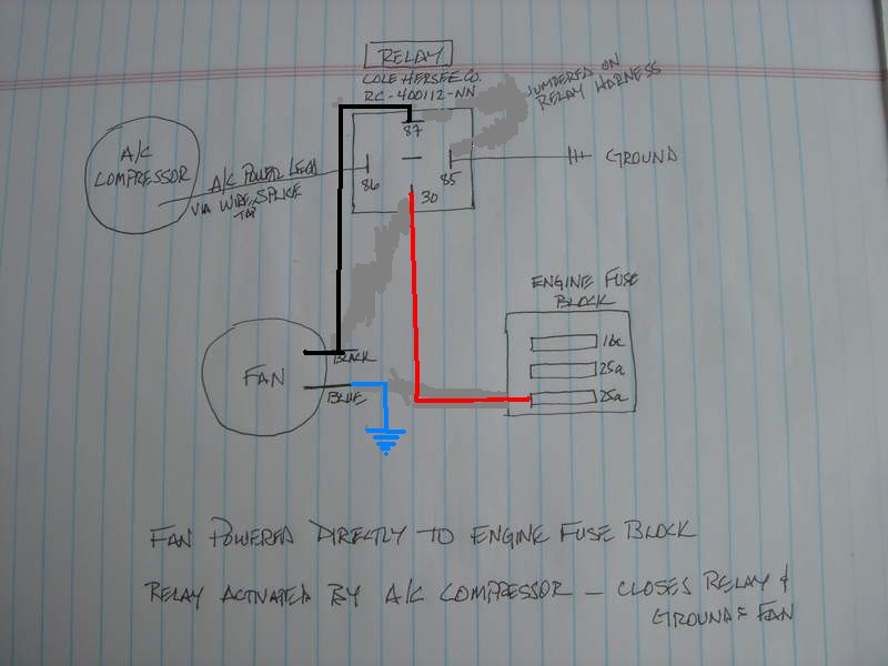
Wiring My Car Air Conditioner For Maximum Cooling 3 Steps With Pictures Instructables
Air conditioning product may result in personal injury and or property damage. Higginbotham on sunday february 17th 2019 in category wiring diagram. Trane Air Handler Wiring Diagram Wiring Diagram Incredible Condenser Intended For Trane Wiring Diagram Trane Diagram Kokopelli Art User manuals trane air conditioner operating guides and service manuals. Trane ac wiring diagram. Trane …

Century Condenser Fan Motor Wiring Diagram Ac Condenser Condensation Basic Electrical Wiring
1- Importance Of Electrical Wiring For Air Conditioning Systems. In the detailed design phase, the electrical designer must size and select the wires/cables, conduits, starters, disconnects and switchgear necessary for supplying power and control to HVAC equipment. This information designed by the electrical designer will be and must appear on ...
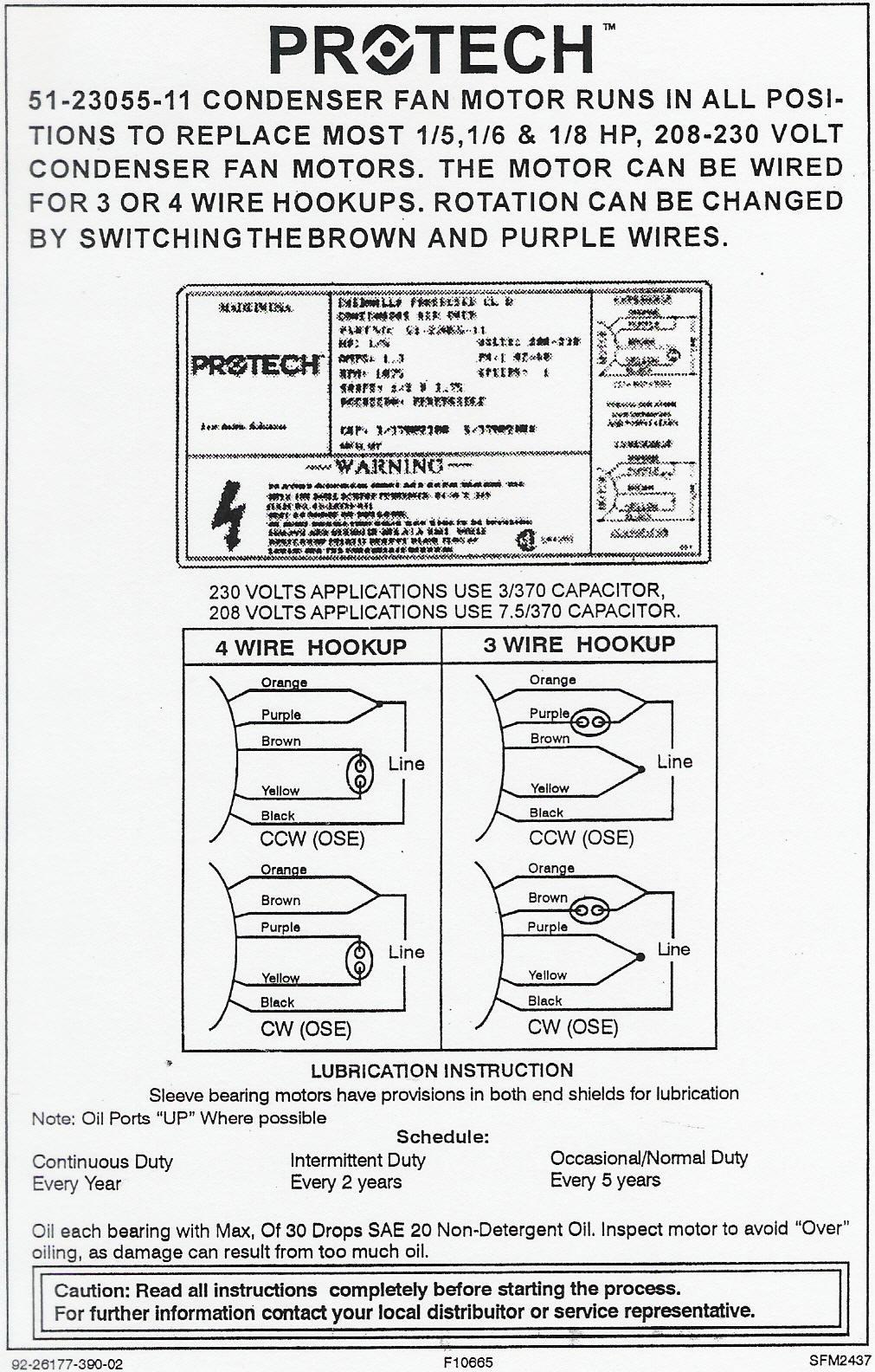
Rheem Ruud Condenser Fan Motor 51 23055 11 Wiring Diagram
Rheem Ac Unit Is Running But No Air Coming Through The Vents In House Doityourself Com Community Forums. Rheem ruud hvac age manuals parts heat pump system dual compressor condensing unit air conditioner faqs for control 5 wires replacing a ge 3 wire condenser fan motor 51 23053 10 kw electric strip kit thermostat wiring diagrams quality resources water heater diagram conditioners and pumps ...
220 240 Wiring Diagram Instructions Dannychesnut Com

Vezi Insecte Cuptor Grevă Schematic Diagram Of Condenser Ghetemagnum Com

Wiring Diagram Sistem Kelistrikan Ac Teknisibali Com

Air Conditioner Condenser Wiring Diagram Rainbowlolipoplife
Radiator Fans Schematic Wiring Diagram Traverse Forum
Furnace Thermostat Wiring And Troubleshooting Hvac How To
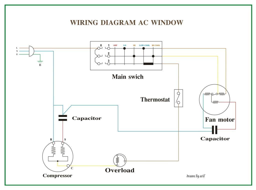
Fixed Ffre1233s1 Frigidaire Window Ac Help Wiring Window A C Blower Motor Applianceblog Repair Forums
1

Solved I Need A Wiring Diagram Run Capacitor For A Bryant Fixya

Ac Motor Kit Picture Ac Motor Capacitor Wiring
Condenser Fan Motor Not Work Ih8mud Forum

Dual Capacitor With Hard Start Wiring Schematic
Hvac Talk Heating Air Refrigeration Discussion

Ac Capacitor Cost And Replacement Ultimate Guide Pickhvac
Ac Wiring Diagram For Android Apk Download

Thermost Wiring Ac Service Tech
Rheem Ruud Condenser Fan Motor 51 23053 11 Wiring Diagram

Heat Pump Thermostat Wiring Chart Diagram Quality 101

Basic Electrical Controls Of Air Conditioning Units Industrial Controls

Marine Accommodation Air Conditioner Piping Diagram Hermawan S Blog Refrigeration And Air Conditioning Systems
0 Response to "35 hvac condenser wiring diagram"
Post a Comment