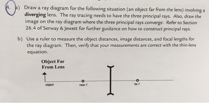
34 draw a ray diagram for the following situation (an object far from the lens)
Step-by-Step Method for Drawing Ray Diagrams. The method of drawing ray diagrams for double convex lens is described below. The description is applied to the task of drawing a ray diagram for an object located beyond the 2F point of a double convex lens. 1. Pick a point on the top of the object and draw three incident rays traveling towards the ... Drawing the ray diagram: Using a scale of 1: 5, we get v = - 2 cm, f = - 3 cm. We draw the ray diagram as follows: (i) Draw the principal axis (a horizontal line). (ii) Draw a convex lens, keeping principal centre (C) on the principal axis. (iii) Mark points F and B on the left side of lens at a distance of 3 cm and 2 cm respectively.
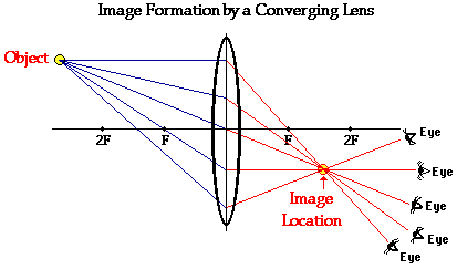
Convex Lenses. When an object is placed at infinity, the real image is formed at the focus. The size of the image is much smaller than that of the object. When an object is placed behind the center of curvature, the real image is formed between the center of curvature and focus. The size of the image is the same as compared to that of the object.
Draw a ray diagram for the following situation (an object far from the lens)
Nov 21, 2015 — Step by step method for drawing ray diagrams. Depends on how far away the object is. Ray diagrams for lenses. Through the center of the lens. 2 ... A Ray Diagram is a simple picture using only 2 or 3 light rays reflected off an object to visualize how images are formed. For a converging lens, the following three rays are drawn: 1. Ray 1 is drawn parallel to the principal axis and then passes through the focal point on the back side of the lens 2. Ray diagrams help us trace the path of the light for the person to view a point on the image of an object. Ray diagram uses lines with arrows to represent the incident ray and the reflected ray. It also helps us trace the direction in which the light travels. Plane Mirror vs Spherical Mirrors.
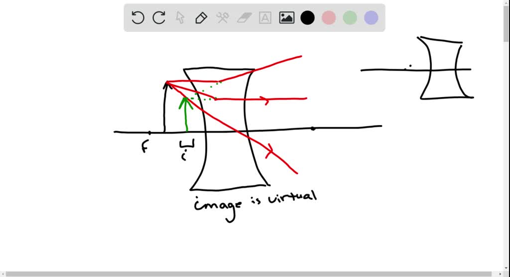
Draw a ray diagram for the following situation (an object far from the lens). For aconvex lens, we draw the ray diagram as follows: Draw a ray from the top of the object straight through the middle of the lens. Its direction is not changed. Draw a ray from the top of the object parallel to the principal axis. It is refracted by the lens to pass through the focal point. F You will see an image that is upright but smaller than the object. This means that the magnification is positive but less than 1. The ray diagram in Figure 13 shows that the image is on the same side of the lens as the object and, hence, cannot be projected—it is a virtual image. Note that the image is closer to the lens than the object. Part A: A diverging lens has of focal length of 15.0 cm. An object is placed 21 cm to the left of the lens. a) draw a ray diagram showing the situation. b) find ...1 answer · 0 votes: a) b) We were unable to transcribe this image Object Far From Lens object near f A) Draw a ray diagram for the following situation ( an object far from the lens) involving a diverging lens. The ray tracing needs to have the three principal rays. B) Use a ruler to measure the object distances, image distances, and focal lengths for the ray diagram. Then verify that your measurements are correct with the thin-lens equation.
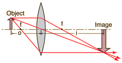
A real object is placed to the right of a converging lens at a distance 2f. The focal length of the lens is f. By carefully drawing a ray diagram for this situation, determine which of the following statements best describes the image formed. Ray diagram for an object placed between 2F and F from a convex lens In a film or data projector, this image is formed on a screen. Film must be loaded into the projector upside down so the ... A converging lens forms an image of an 8.00-mm-tall real object. The image is 12.0 cm to the left of the lens, 3.40 cm tall, and erect. What is the focal length of the lens? Where is the object located? ————- Get the location first. Since the image is to the left of the lens, it is virtual, and s′ is negative. From m = −s′/s ... A lens is considered to be thin if its thickness t is much less than the radii of curvature of both surfaces, as shown in .In this case, the rays may be considered to bend once at the center of the lens. For the case drawn in the figure, light ray 1 is parallel to the optical axis, so the outgoing ray is bent once at the center of the lens and goes through the focal point.
Draw a ray diagram for the following situation (an object far from the lens) involving a diverging lens. The ray tracing needs to have the three principal rays. Also, draw the image on the ray diagram where the three principal rays converge. Refer to Section 26.4 of Serway & Jewett for further guidance on how to construct principal rays. A draw a ray diagram for the following situation an object far from the lens involving a diverging lens. Step by step method for drawing ray diagrams. If an object is located between the focal point and converging lens the image will be. Through the center of the lens. Also draw the image on the ray diagram where the three principal rays converge. A) Draw a ray diagram for the following situation (an object far from the lens) involving a diverging lens.The ray tacing needs to have the three principal rays.Also draw the image on the ray diagram where the three principle waves converge.. B) Use a ruler to measure the object distances, image distances, and focal lengths for the ray diagram. How far is the object placed from the lens? Draw the ray diagram. Answer-Focal length of concave lens (OF 1), f = - 15 cm. Image distance, v= - 10 cm. According to the lens formula, The negative value of u indicates that the object is placed 30 cm in front of the lens. This is shown in the following ray diagram. 12. An object is placed at a ...
1
Construct ray diagrams to show where the images of the following objects are located. Draw in the complete image (approximated by an arrow) and describe its characteristics (real or virtual, enlarged or reduced in size, inverted or upright).
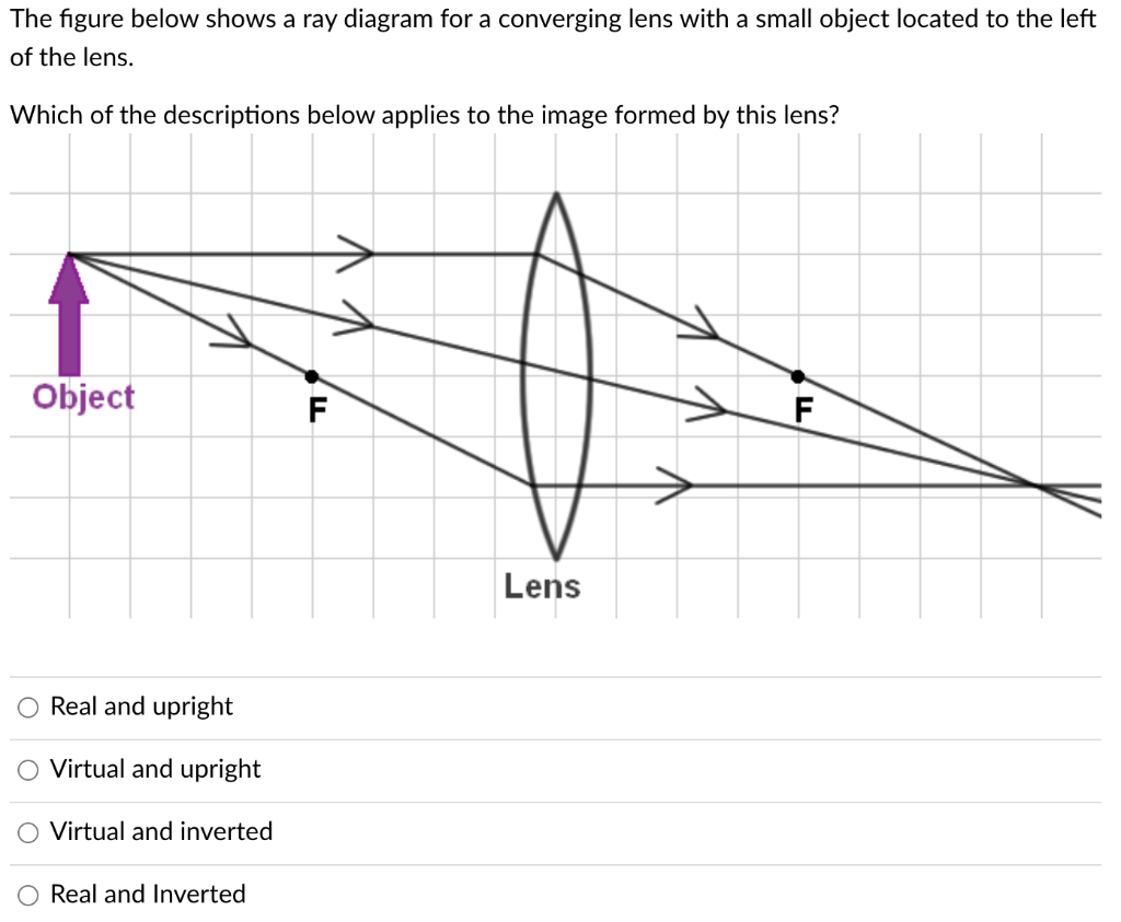
Solved The Figure Below Shows A Ray Diagram For A Converging Chegg Com
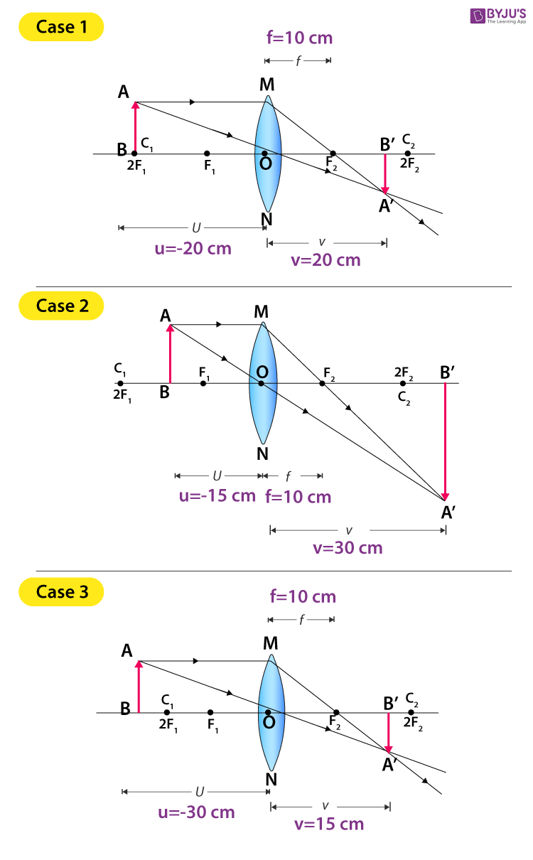
An object is placed 30 cm in front of a converging lens with focal length 10 cm. Find the object distance and magnification. Example An object is placed 30 cm in front of a converging lens with focal length 10 cm. Find the object distance and magnification. Ray diagram. 11 1 pq f + = 111 qf p = − fp q pf = − (10)(30) 15cm 30 10 == − q15 ...

Draw A Ray Diagram For The Following Situation An Object Far From The Lens Involving A Homeworklib
f = “focal length” = distance of F from lens. • d. 0 is positive if the object is on the same side of the lens as the incident rays.
Ray Diagrams For Lenses
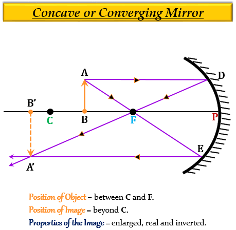
The method for drawing ray diagrams for concave mirror is described below. The method is applied to the task of drawing a ray diagram for an object located beyond the center of curvature (C) of a concave mirror. Yet the same method works for drawing a ray diagram for any object location. 1. Pick a point on the top of the object and draw two ...

Draw A Ray Diagram To Show The Formation Of Image By A Concave Mirror For An Object Placed Between Its Pole And Focus State Three Characteristics Of The Image
a) Draw a ray diagram for the following situation (an object far from the lens) involving a diverging lens. The ray tracing needs to have the three principal rays. Also, draw the image on the ray diagram where the three principal rays converge. Refer to Section 26.4 of Serway & Jewett for further guidance on how to construct principal rays.

Cbse Ncert Solution For Class 10 Physics Light Reflection Refraction
b. Now let's say that the focal point of the lens is 10 cm and the object is 25 cm from the converging mirror. Calculate the image distance from the mirror. c.1 answer · Top answer: Given Data: • The focal length of the mirror is f=−10cmf=−10cm (converging). • The object distance for the mirror is {eq}u = -...
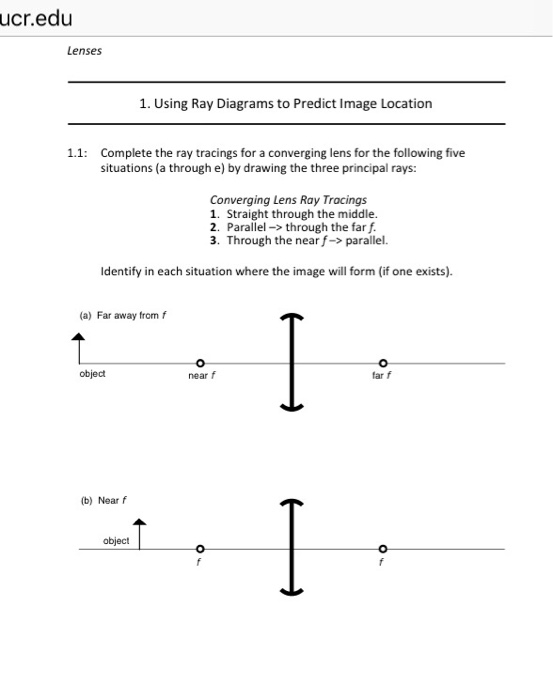
Solved Ucr Edu Lenses 1 Using Ray Diagrams To Predict Image Chegg Com
Ray Diagrams for Lenses. The image formed by a single lens can be located and sized with three principal rays. Examples are given for converging and diverging lenses and for the cases where the object is inside and outside the principal focal length. The "three principal rays" which are used for visualizing the image location and size are:
Draw The Ray Diagram For Getting A Magnified Inverted Real Image By Using A Convex Lens Physics Topperlearning Com T315qpdd
Drawing a ray diagram for an object far from a convex lens requires how many rays. Draw a ray diagram for the following situation an object far from the lens. Extend both rays as much as you can line in blue. Ray diagrams 3 of 4 concave and convex lenses and mirrors. Parallel light rays duration.

Ray Diagrams Lenses Physics Lab Video Lesson Transcript Study Com
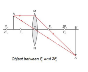
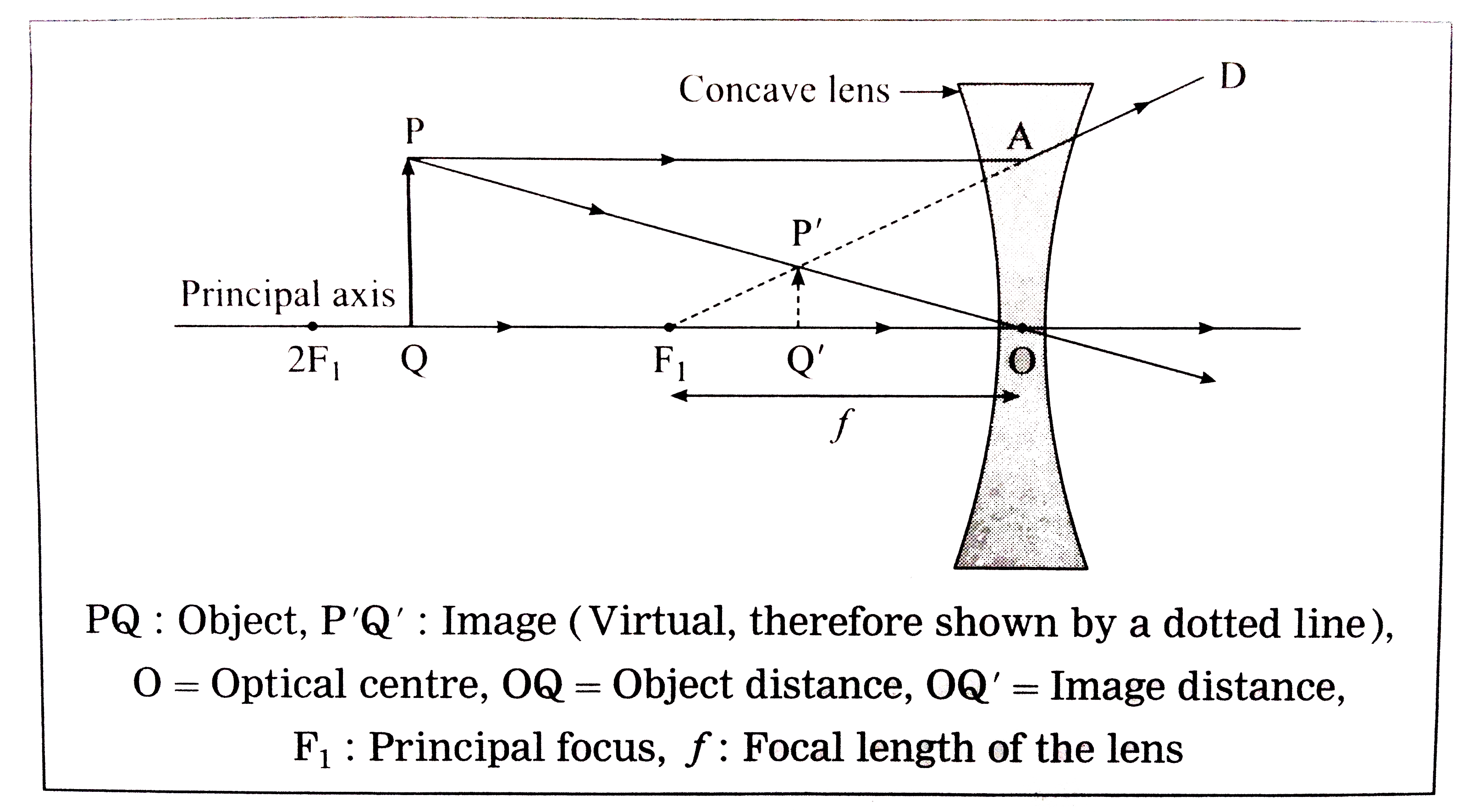
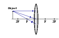
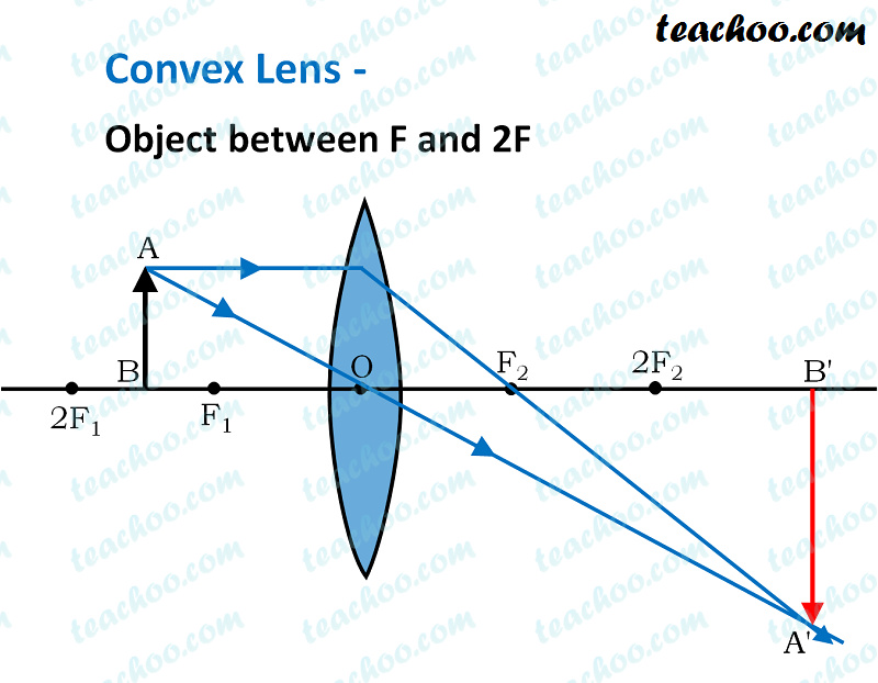
Here, Object AB is beyond 2F 1. First, we draw a ray parallel to principal axis. So, it passes through focus after refraction. We draw another ray which passes through Optical Center. So, the ray will go through without any deviation. Where both rays meet is point A'. And the image formed is A'B'. This image is formed between F 2 and 2F 2.

Draw Ray Diagrams For The Following Positions And Explain The Nature And Position Of Image Object Is Placed Between F2 And Optic Centre P
To Find The Image Distance For Varying Object Distances In Case Of A Convex Lens With Ray Diagrams The lens is a transparent material which is bound by two surfaces. It has a principal axis, principal focus, centre of curvature of lens, aperture and optical centre.

Consider A Les That Ha A Focal Hofan Object Is Locatem Away Fronm This Lens In Homeworklib
b) Use ruler to measure the object distances, image distances_ and focal lengths for the ray diagram. Then, verify that your measurements are correct with the ...4 answers · Top answer: All right, So this is similar to problem 54. From the diagram, we see that the ray is bending ...
Physics Tutorial Refraction And The Ray Model Of Light
Follow the steps above to solve the following problem: An object is 9.0 from a converging lens with a focal length of 2.8.Use ray tracing to determine the location of the image. Part A The diagram below shows the situation described in the problem. The focal length of the lens is labeled; the scale on the optical axis is in centimeters. Draw the three special rays, Ray 1, Ray 2, and Ray 3, as ...

Lesson Explainer Drawing Ray Diagrams For Convex Lenses Nagwa
A) Draw a ray diagram for the following situation ( an object far from the lens) where the three principle waves converge. B) Use a ruler to measure the object distances, image distances, and focal lengths for the ray diagram. Then verify that your measurements are correct with the thin-lens equation.
A Draw Ray Diagrams To Show The Formation Of Image Tutorix
The method of drawing ray diagrams for double convex lens is described below. The description is applied to the task of drawing a ray diagram for an object located beyond the 2F point of a double convex lens. 1. Pick a point on the top of the object and draw three incident rays traveling towards the lens.
Solved Draw A Ray Diagram For The Following Situation An Chegg Com
One-half of a convex lens of focal length 2 0 c m is covered with a black paper. Show the formation of image of an object placed at 2 Fa of such covered lens with the help of a ray diagram . Medium
Solved Draw A Ray Tracing Diagram For The Following Situation An Object Is Placed Between The Focal Point F And The Convex Lens Also Indicate If The Image Is Real Or Virtual And
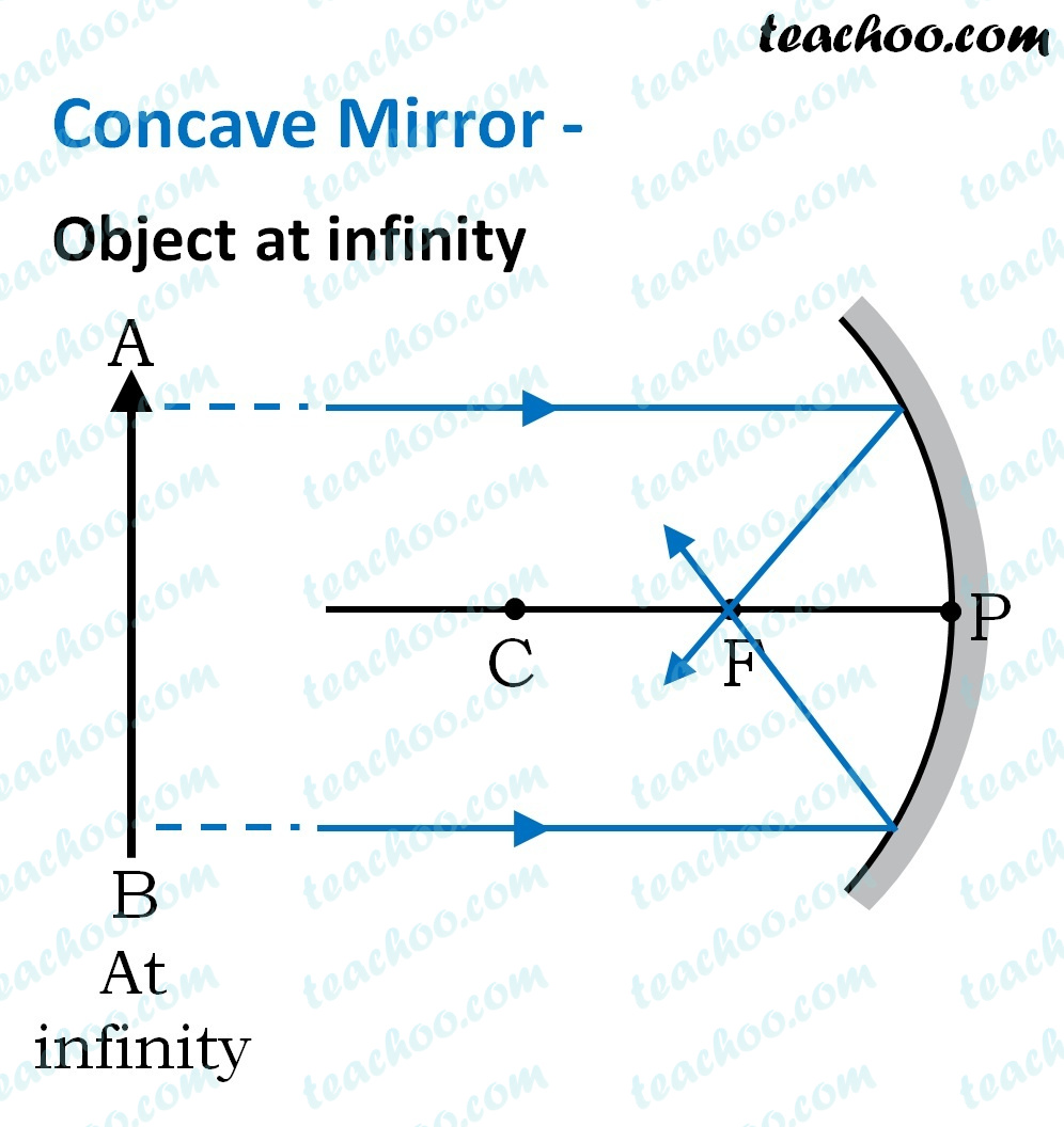
a) For convenience of discussion we assume that the light passes through the lens from left to right. Ray diagrams will follow this convention. (b) The focal point of a lens is found by allowing a bundle of mutually parallel rays to enter the lens (i.e., from an object infinitely far from the lens). The lens alters the direction of these rays,

Draw The Ray Diagram 3 Rays For The Following To Determine The Image Find The Distance Homeworklib
Ray diagrams help us trace the path of the light for the person to view a point on the image of an object. Ray diagram uses lines with arrows to represent the incident ray and the reflected ray. It also helps us trace the direction in which the light travels. Plane Mirror vs Spherical Mirrors.
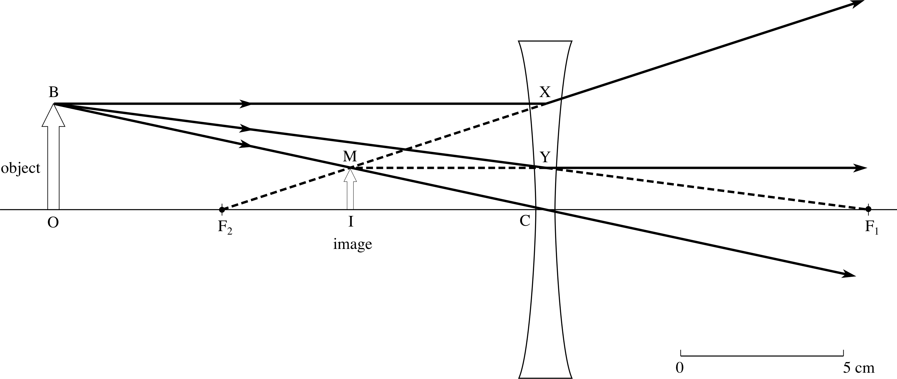
Draw Ray Diagrams Showing The Image Formation By A Concave Lens When An Object Is Placed A Between Focus And Twice The Focal Length Of The Lens B Beyond Twice The Focal
A Ray Diagram is a simple picture using only 2 or 3 light rays reflected off an object to visualize how images are formed. For a converging lens, the following three rays are drawn: 1. Ray 1 is drawn parallel to the principal axis and then passes through the focal point on the back side of the lens 2.
1
Nov 21, 2015 — Step by step method for drawing ray diagrams. Depends on how far away the object is. Ray diagrams for lenses. Through the center of the lens. 2 ...

Draw Ray Diagram Showing The Image Formation By A Convex Lens When An Object Is Placed At Infinity
To Find Image Distance For Varying Distance Of A Concave Lens

Q36 Draw A Ray Diagram To Show Lido
Solved Draw A Ray Tracing Diagram For The Following Situation An Object Is Placed Between The Focal Point F And A Concave Mirror Also Indicate If The Image Is Real Or Virtual And If

Concave And Convex Mirrors Ray Diagram For Convex And Concave Mirror

A Draw A Ray Diagram For The Following Si Clutch Prep

Get Answer A Draw A Ray Diagram For The Following Situation An Object Transtutors

Draw The Ray Diagram To Show The Formation Of Image For The Object Of Height 1 Cm Placed At 5 Cm Distance In Front Of A Convex Mirror Having The Radius
12 2 Lenses Drawing Ray Diagrams
Physics Tutorial Refraction And The Ray Model Of Light
Concave Mirror Ray Diagram Image Formation Table Teachoo
Solved Cl 6 An Object Is Placed At Distance D0 From A Converging Lens Such That The Height Of The Image Equals The Height Of The Object Draw Ray Diagram To Scale
Pplato Flap Phys 6 3 Optical Elements Prisms Lenses And Spherical Mirrors

A An Object Is Placed 10 Cm From A Lens Of Focal Length 5 Cm Draw The Ray Diagrams To Show Youtube
Convex Lens Ray Diagram Image Formation Table Teachoo
0 Response to "34 draw a ray diagram for the following situation (an object far from the lens)"
Post a Comment